Advertisement
Table of Contents
- 1 Table of Contents
- 2 Precaution
- 3 Bill of Materials
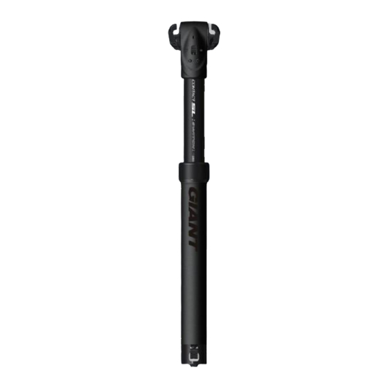
- 4 Contact Switch Seatpost – External Cable Routing Position
- 5 Saddle Clamp Unit
- 6 Contact Switch Seatpost Cartridge
- 7 Specifications
- 8 Internal Cable Routing Option
- 9 External Cable Routing Option
- 10 Tools
- 11 Procedures
- 12 Disassembling & Reassembling Cartridge
- 13 Installing Seatpost on Bike
- 14 Recommended Torques
- 15 Operation of Seatpost
- 16 Giant Limited Warranty
- Download this manual
Advertisement
Table of Contents

Related Manuals for Giant CONTACT SL SWITCH


Summary of Contents for Giant CONTACT SL SWITCH
- Page 1 GIANT CONTACT SL SWITCH SEATPOST USER’S MANUAL...
- Page 2 INTRODUCTION BILL OF MATERIALS SPECIFICATIONS & TOOLS PROCEDURES DISASSEMBLING & REASSEMBLING CARTRIDGE INSTALLING SEATPOST ON BIKE OPERATION OF SEATPOST GIANT LIMITED WARRANTY ...
- Page 3 INTRODUCTION Congratulations on the purchase of your new GIANT CONTACT SWITCH seatpost. This product is designed to help you ride more efficiently in technical situations and ultimately help you enjoy your rides. When used properly, this product will provide years of use.
- Page 4 BILL OF MATERIALS Contact Switch seatpost – External Cable Routing Position Remote Control Unit Saddle Clamp Body Seatpost Stanchion Dust Wiper Bearing Retainer Barrel Seatpost Lower Tube Cable Casing Lower Cap Please refer to the illustration in the Table of Contents for internal cable routing position view.
- Page 5 Saddle Clamp Unit – Ref # Description Clamp bolt: M6 mm hex key, Max Torque: 8.0 Nm | 70 lbs-in | 80 kgf-cm Washer Tube fixing screw Top tube Saddle outer clamp – Down (7 / 9 mm rail only) Saddle outer clamp –...
- Page 6 SPECIFICATIONS The Contact Switch seatpost is designed to have the remote cable run either internally or externally. Internal cable routing requires the cartridge trigger to be at the bottom of the post; external routing requires the trigger to be at the top. Internal cable routing option External cable routing option Specifications...
- Page 7 PROCEDURES DISASSEMBLING & REASSEMBLING CARTRIDGE Disassembling The Cartridge Cartridge fixing screws Remove the lower cap Remove the cartridge fixing Remove screws from the using a 8mm hex key. screws from saddle clamp lower cap. Remove the body using a 2.5 mm hex lower cap from cartridge.
- Page 8 BB parts before routing the cable inside the frame. It is a complex job to remove and reinstall these parts, we recommend finding an authorized GIANT dealer for assistance, if you choose to use the internal routing option.
- Page 9 Assemble the remote control cable to the seatpost and the remote control unit. I. Hang the cable stopper on the seatpost. Install the remote control cable for external cable: Upper compressing lever Thread the remote control cable through the hole in the saddle clamp body.
- Page 10 Mount the control unit to the handlebar and fasten within Thread cable to the cable 3mm hex key. hole. Recommended Torque: 1.6Nm | 14 lbs-in | 16 kgf-cm III. Adjust remote cable Adjust the cable so the cable casing, barrel and remote unit are tightly connected so the control lever is properly positioned and the cartridge moves properly.
- Page 11 GIANT. This warranty extends from the date of purchase, applies only to the original owner, and is not transferable. In no event shall GIANT be responsible for any direct, incidental or consequential damages, including, without limitation, damages for personal injury, property damage, or economic losses, whether based on contract, warranty, negligence, product liability, or any other theory.
- Page 12 ‒ Labor charges for part replacement or changeover. Except as is provided by this warranty and subject to all additional warranties, GIANT and its employees and agents shall not be liable for any loss or damage whatsoever (including incidental and consequential loss or damage caused by negligence or default) arising from or concerning any GIANT product.
Need help?
Do you have a question about the CONTACT SL SWITCH and is the answer not in the manual?
Questions and answers