Table of Contents
Advertisement
Quick Links
Advertisement
Table of Contents

Subscribe to Our Youtube Channel
Related Manuals for Messoa SPD982


Summary of Contents for Messoa SPD982
- Page 1 Speed Dome Network Camera SPD982 SPD983 User Manual 201607 982 983 A2...
-
Page 2: Table Of Contents
Table of Contents Product Overview Physical Characteristics Installation Package Content Installation 2.2.1 Checking Appearance 2.2.2 Disassembling the Camera 2.2.3 Inserting Micro SD Card 2.2.4 Installing Desiccant 2.2.5 Assembling Camera 2.2.6 Connecting Wires 2.2.7 Connecting Safety Cord 2.2.8 Before Powering Camera Connection Network Topology System Requirements... - Page 3 4.2.9 Event Log 4.2.10 PTZ Settings Appendix A: Specifications of 3MP Speed Dome Network Camera Appendix B: Specifications of 3MP Speed Dome Network Camera...
- Page 4 WARNING • This unit operates at AC 24V/ PoE+ (IEEE 802.3at type 2). • Installation and service should be performed only by qualified and experienced technicians and comply with all local codes and rules to maintain your warranty. • To reduce the risk of fire or electric shock, do not expose the product to rain or moisture. •...
-
Page 5: Fcc Compliance Statement
FCC Compliance Statement Information to the user: This unit has been tested and found to comply with the limits for a Class B digital device pursuant to Part 15 of the FCC Rules. Operation is subject to the following two conditions: (1) this device may not cause harmful interference, and (2) this device must accept any interference received, including interference that may cause undesired operation. -
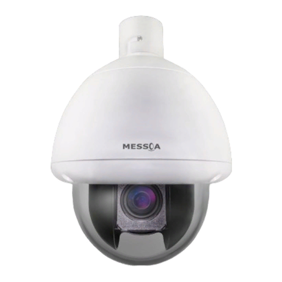
Page 6: Product Overview
Product Overview Physical Characteristics Unit: mm Figure 1 - 1: Physical Dimension Figure 1 - 2: Pictorial Index... - Page 7 Interface Description The bubble-like top cover acts like an upper protection for camera body. By Top Cover loosening the 4 anti-drop screws embedded, user can further install Micro SD card and desiccant onto the internal camera body. The rear cap covers the internal interface panel where user can, after loosening Rear Cap the 2 screws, freely connect required cables with corresponding ports when necessary.
-
Page 8: Installation
Installation Package Content Check if everything in the packing box matches to the order form and the packing slip. All items listed below should be included in the packing box. • IP Speed Dome Camera * 1 • Safety Wire * 1 •... -
Page 9: Disassembling The Camera
2.2.2 Disassembling the Camera Please refer to the steps with figures below for correct disassembling order. Loosen the 4 top cover screws and detach the top cover away from the camera body. Top Cover Screws * 4 Figure 2 - 1: Disassembling the Camera Remove the protective materials that cover the lens module for embracive safety on delivery. -
Page 10: Inserting Micro Sd Card
2.2.3 Inserting Micro SD Card The speed dome camera is equipped with micro SD card slot for local recording files storage. Please follow the steps below for the appropriate procedure of card installation. Loosen the 2 lens cover screws and detach the cover away from the camera body. Insert a micro SD card into the card slot indicated red within the figure below followed by turning the lever in horizontal manner to lock the inserted card securely. -
Page 11: Installing Desiccant
2.2.4 Installing Desiccant In order to prevent condensation from forming within the camera body, the included desiccant pack is provided for user to manually install prior to commencing to operate the camera. First hold the desiccant pack upright with one hand and unfold the desiccant slot with the other hand followed by putting the desiccant vertically into the slot in place. -
Page 12: Connecting Wires
2.2.6 Connecting Wires To fulfil the waterproof functionality, it is necessary to utilize the included rain-tight compression kit while connecting wires with the camera. First thread the required Ethernet wire through the compression cap and compression core in proper order followed by threading the cable into the rear cap to connect with the corresponding port/interface on the rear panel. -
Page 13: Connecting Safety Cord
2.2.7 Connecting Safety Cord Connect the attached safety cord with one end to the mounting surface and the other end to the safety-cord screw of the camera. Depending on different applications, please connect the safety cord to the corresponding safety-cord screw on varied surfaces as the following figures illustrating. -
Page 14: Connection
Connection Network Topology The camera, which is equipped with Ethernet RJ-45 network interface, can deliver live view image in real time via both Internet and Intranet manners. Please refer to the skeleton drawings shown below for understanding. Figure 3 - 1: Network Topology System Requirements Below table lists the minimum requirement to implement and operate the camera. -
Page 15: Connecting Process
Connecting Process 3.3.1 Default IP address Since this is a network-based unit, an IP address must be assigned at the very first. The unit’s default IP address is 192.168.1.30 and sub mask is 255.255.255.0. However, if you have a DHCP server in your network, the unit would obtain an IP address automatically from the DHCP server so that you don’t need to change the camera’s IP address. -
Page 16: Viewing Preparation
Viewing Preparation Images of the unit can be viewed through Microsoft Internet Explorer 8 or above. Before viewing, follow these steps to enable the display. Enable Cookies as instructions below In Internet Explorer, click Internet Options on the Tools menu. ... - Page 17 Scroll down to the ActiveX controls and plug-ins radio buttons and set as follows: 【 Download signed ActiveX controls 】 Prompt (recommended) 【 Download unsigned ActiveX controls 】 Prompt 【 Initialize and script ActiveX not marked as safe for scripting 】 Prompt Figure 3 - 4: Security Settings 2/4 【...
- Page 18 【 Run ActiveX controls and plug-ins 】 Enable 【 Script ActiveX controls marked safe for scripting* 】 Enable Figure 3 - 6: Security Settings 4/4 Press OK to save the settings. Close all Microsoft Internet Explorer Windows and restart a new window. This will allow the new settings taking effect. ...
-
Page 19: Ip Finder
IP Finder works only in Microsoft Windows XP, Microsoft Windows Vista, and Microsoft Windows 7 or above. Steps to get the utility program running are listed below. Download IP Finder from MESSOA Website to the computer. Double click on IPFinder.exe in the IP Finder folder, and the IP Finder window should pop out. -
Page 20: Administration And Configuration
Administration and Configuration Live View Figure 4 - 1: First Login Page After accessing and login to the IP address of the unit, the screen will be shown as the above screenshot. There are 2 main options on the upper left side: “Live View” and “Configuration”. While the upper right side indicates your current login user level with “Logout”... - Page 21 player for live view. The “Stream” permits users to toggle among each stream settings for better adaptation in every different network condition, for which you may refer to “Edit Profiles & Streams” for more details. The PTZ panel below is for users to operate PTZ functions, which will be further detailed explicitly in the later part “4.2.1 PTZ Control”.
-
Page 22: Configuration
Configuration After clicking the “Configuration” option, the screen will be shown as below with several menu options for users to configure on the left side. We will thoroughly introduce them one by one in the following chapters. Figure 4 - 3: Configure 4.2.1 PTZ Control The control panel of PTZ is for users to conveniently execute pan/tilt/zoom functions with ease. - Page 23 Descriptions Move camera focus in 8 directional arrows To zoom in camera focus in close view To zoom out camera focus in wide view Adjust focus to near distance Adjust focus to far distance Activate One Push AF (Auto Focus) Drag the bar to adjust Pan/Tilt Speed Drag the bar to adjust Zoom speed Perform Auto Scan...
-
Page 24: Information
4.2.2 Information System Information Users can view, after clicking “System Information”, the detailed information related to the camera including Firmware Version, MAC Address as well as Model Name. Figure 4 - 5: System Information 4.2.3 Image Parameters The Image Parameter contains several basic display settings like resolution, codec, FPS, GOP and so on. In addition, it has some extending settings including exposure, color, lens control and white balance for the camera. - Page 25 Figure 4 - 6: Codec Settings...
- Page 26 Item Option Description MJPEG: Each video frame is individually compressed as single jpeg image with full-scale contents itself and can be retouched freely with ease. However, due to completeness of each frame, it brings about larger file size MJPEG and thus easily tends to lose frames under limited network bandwidth. Video Codec H.264 H.264: The latest best-renowned video compression format, it adopts...
- Page 27 Table 4 - 4: Correlations of Resolution/Streams/FPS/Codes - NTSC Resolution Single stream Double stream Triple stream 2048x1536 @ 20fps, 640x480 @ 20fps 2048x1536 @ 20fps, 640x480 @ 20fps, 640x480 @ 3fps 2048×1536 @ 20fps 2048x1536 @ 20fps, 320x240 @ 20fps 2048x1536 @ 20fps, 320x240 @ 20fps, 640x480 @ 3fps 2048×1536 (H.264/MJPEG)
- Page 28 Exposure Figure 4 - 7: Exposure Settings ● Auto Exposure • Exposure modes control the light intensity of picture. There are three auto exposure types, which are AES (Automatic Electronic Shutter), ALC (Automatic Lens Control), and Flickerless for adjustment depending on conditions differed. •...
-
Page 29: White Balance
• Noise Reduction: It is the process of removing noises from a signal and be set from 0 - 255 to decrease noise on the screen. “255” indicates the most effectiveness for noise reduction. • BLC: Set an area for Backlight Compensation. Backlight Compensation is a function that achieves the brightness of a selected area to optimal image level. - Page 30 Basic Color Figure 4 - 10: Basic Color Settings ● Brightness Set image brightness from level -255 to 255. Selecting 255 provides the highest brightness. ● Contrast Set image contrast from level 0 to 255. Selecting 255 provides the highest contrast. ●...
-
Page 31: Privacy Zone
Privacy Zone Privacy Zone enables users to black out a specific portion of the screen for privacy concern. There are up to 8 sets of privacy zones for users to define. After setting up a privacy zone, the live view screen will appear a frame, whose color, size, and position can be customized by users’... -
Page 32: Network Settings
4.2.4 Network Settings Network Below part explains how to configure a wired network connection for the camera. Figure 4 - 12: Network Settings ● Network Settings • View Current Network Settings: Click on the “View” button to view your current network settings. A pop-up window will display information such as IPv4 Address, Subnet Mask, Default Gateway, Primary and Secondary DNS. - Page 33 ● IPv4 Address Configure • DHCP: If this option is checked, the unit will automatically obtain an available dynamic IP address from the DHCP server each time it connects to a LAN network environment. • IP4 Address: Manually input IP address when DHCP is checked off. •...
- Page 34 In this page, users can set FTP connection related settings. Figure 4 - 14: FTP Settings ● Basic Setting • Login ID: Enter a login ID to be allowed to connect with FTP. • Password: Enter a password associated with the login ID. •...
- Page 35 RTSP RTSP is a standard protocol for connecting a client to establish and control streaming data over the web. If you want to allow third-party devices or software to access video/audio streams from the IP camera over the network, you must configure the RTSP ports.
- Page 36 ● Multicast The address for Multicast is roughly same with Unicast as the above, whilst the stream name will be followed by a low case “m” as mentioned previously. Please refer to the samples below: • rtsp://(camera IP address)/(Multicast stream 1) •...
- Page 37 ● Read/Write Community String Enter the names of Read Community String and Write Community String. ● Trap Trap under SNMP allows an agent to notify the management station of significant events by way of an unsolicited SNMP message, the asynchronous notification. Tick “ON” or “OFF” to enable or disable trap function here. Input IP address of Trap Host.
- Page 38 IP Filter Under this menu, users can manually define several IP addresses to be allowed or denied to access camera. Figure 4 - 18: IP Filter Settings ● Protocol: Select protocol types between TCP and UDP or BOTH to be enabled for inputted IP addresses. ●...
-
Page 39: Account Management
4.2.5 Account Management Account Setting Figure 4 - 19: Account Settings ● Admin: The camera privileged control relates to “Admin” level, which can handle both live view and all the configuration settings. The default username and password for Admin are “admin” and “1234” respectively. ●... -
Page 40: Event Settings
4.2.6 Event Settings Motion Detection This function is designed to trigger a corresponding action when the unit detects motion(s). Figure 4 - 20: Motion Detection Settings ● Enable Set “ON” to activate motion detection function. ● Sensitivity Choose different 3 levels of detecting sensitivity. “High”: Motion is activated with slight changes in brightness or motion. “Low”: Motion is activated with big changes in brightness or motion. -
Page 41: Email Notification
Figure 4 - 21: Alarm Input / Output Settings Please click “Save” button to save your settings or click “Reset to Default” to set all the data and options Note back to the factory default settings. Email Notification ● SMTP Recording Condition: Simple Mail Transfer Protocol (SMTP) is an Internet standard for e-mail service across networking. - Page 42 » No_Auth: No restriction » SMTP_Plain: PLAIN is the name of a registered SASL authentication mechanism which serves as a parameter to the AUTH command. The PLAIN authentication mechanism is described in RFC 2595. Plain is the least secure of all the SASL authentication mechanisms since the password is sent unencrypted across the network.
-
Page 43: Recording Settings
4.2.7 Recording Settings Network Recording Users can save video files via FTP server by setting FTP recording condition beforehand. ● FTP Recording Conditions: You can store the video files by one of the modes including Schedule recording, recording triggered by Alarm Input, or recordings triggered by Motion detection. - Page 44 ● Recording Settings: This function is to define the way to record video once an alarm or motion event is triggered. Figure 4 - 27: Recording Settings • Pre-event Image (pcs): Set a number of images to be recorded immediately before an event occurs. •...
-
Page 45: System Settings
4.2.8 System Settings Date & Time ● Current Server Time The server current date/time is displayed here. Figure 4 - 29: Date & Time ● Synchronization Mode There’re 3 modes for users to set date/time. • Manual: Select it to manually set your date/time with pop-up window. •... - Page 46 Audio Figure 4 - 30: Audio Settings • Type: Two audio codecs G.711 A-law/G.711 µ-law can be chosen from. • Enable: Set "ON" to activate audio input when audio input device is plugged. • Level: The sound levels are selectable: Low/Middle/High for audio input. Please click “Save”...
-
Page 47: Event Log
Initialize Figure 4 - 32: Initialize Settings ● Video Type Select “NTSC” or “PAL” as required. Flickering by fluorescent light can be reduced by selecting “PAL” for the power frequency 50Hz, “NTSC” for the power frequency 60Hz ● Import User Configurations Press “Browse”... -
Page 48: Ptz Settings
4.2.10 PTZ Settings Basic Setting Figure 4 - 34: Basic Setting ● Basic Setting: • Power on action: Set the initialized action when powering on the camera. » Default: Camera will be positioned based on the factory defaults. » Home: Camera will automatically move to its home position. »... - Page 49 ● Focus Setting: • Focus Mode: 3 modes for choosing and the default is ‘Auto’ . Each is described as following. » Auto: Automatically adjust the focus position to maximize the high frequency content of the picture in the center. »...
-
Page 50: Patrol Setting
Patrol Setting The camera provides up to 4 sets of auto patrol group for user configurations. The function of auto patrol will continuously scan maximum 128 preset points without limited scan range. Simply tick on each position to enable it. Position number with tick sign indicates it is selected now. -
Page 51: Pattern Setting
Pattern Setting There are maximum 4 groups for users to define customized pattern, which consists of continuous actions, either by preset positions or 8 directional control or both actions combined. In addition to continuous actions, time interval between each action by users can be remembered under pattern mode as well. The very difference of pattern mode from patrol mode is that it enables users to set their preferred viewing points more flexibly and freely, not limited within chosen from preset positions to build up a patrolling group. -
Page 52: Appendix A: Specifications Of 3Mp Speed Dome Network Camera
Appendix A: Specifications of 3MP Speed Dome Network Camera Video Sensor Type 1/2.8” image sensor (CMOS) Active Pixels 2304 x 1536 (HxV) Compression H.264 / MJPEG Streaming Triple simultaneous streams with multiple video profile QXGA(2048x1536), 1080P, 1280x960, 720P, SVGA(800x 600), VGA(640x480), 640x360, Resolution QVGA(320x240), 320x180 3MP 4:3 (2048x1536) at 20 fps;... - Page 53 Enhanced Digital WDR 3DNR Privacy Zone Yes, up to 8 privacy zones Image Orientation Mirror, Flip Frequency Control NTSC (60Hz) / PAL (50Hz) Date & Time Stamp Intelligent Video & Event Management Motion Detection 3-level sensitivity Ethernet Detection Network lost detection Events Motion detection, Ethernet detection, external alarm Event snapshot to remote FTP storage/ email recipients,...
- Page 54 Storage Temperature -20°C ~ 60°C (-4°F ~ 140°F) Regulatory Approvals CE, FCC, RoHS Ordering Information NTSC: SPD982-N2-US-MES; Model No. PAL: SPD982-P2-EU-MES Pendent Mount: SAD702, SAD714 Wall Mount: SAD703, SAD713 Parapet Wall Mount: SAD706 Accessories Corner Mount: SAD707 Pole Mount: SAD708 Pipe Extension Bracket: SAD709 1.
-
Page 55: Appendix B: Specifications Of 3Mp Speed Dome Network Camera
Appendix B: Specifications of 3MP Speed Dome Network Camera Video Sensor Type 1/2.8” image sensor (CMOS) Active Pixels 2304 x 1536 (HxV) Compression H.264 / MJPEG Streaming Triple simultaneous streams with multiple video profile QXGA(2048x1536), 1080P, 1280x960, 720P, SVGA(800x 600), VGA(640x480), 640x360, Resolution QVGA(320x240), 320x180 3MP 4:3 (2048x1536) at 20 fps;... - Page 56 Enhanced Digital WDR 3DNR Privacy Zone Yes, up to 8 privacy zones Image Orientation Mirror, Flip Frequency Control NTSC (60Hz) / PAL (50Hz) Date & Time Stamp Intelligent Video & Event Management Motion Detection 3-level sensitivity Ethernet Detection Network lost detection Events Motion detection, Ethernet detection, external alarm Event snapshot to remote FTP storage/ email recipients,...
- Page 57 Storage Temperature -20°C ~ 60°C (-4°F ~ 140°F) Regulatory Approvals CE, FCC, RoHS Ordering Information NTSC: SPD983-N2-US-MES; Model No. PAL: SPD983-P2-EU-MES Pendent Mount: SAD702, SAD714 Wall Mount: SAD703, SAD713 Parapet Wall Mount: SAD706 Accessories Corner Mount: SAD707 Pole Mount: SAD708 Pipe Extension Bracket: SAD709 1.
Need help?
Do you have a question about the SPD982 and is the answer not in the manual?
Questions and answers