Table of Contents
Advertisement
Quick Links
INSTRUCTION MANUAL
Please read this manual thoroughly before use, and keep it handy for future
reference.
TABLE OF CONTENTS
1. CAUTIONS ................................................................................. 2
2. SYSTEM COMPONENTS ...............................................................2
3. SYSTEM CONNECTION ............................................................... 2
4. PIN CONNECTIONS ..................................................................... 3
5. PARTS NAMES & FUNCTIONS ...................................................... 4
6. PUSH BUTTONS AND THEIR FUNCTIONS .......................................5
7. SETTING MENU ...........................................................................6
8. SUB MENU ................................................................................. 7
9. OSD FUNCTION DESCRIPTION ...................................................... 8
10. SYSTEM EXTENSIONS ............................................................... 11
11. SPECIFICATIONS ........................................................................15
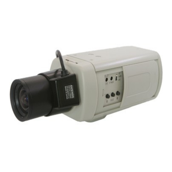
Day&Night
Hi-Res
Colour CCD
Camera
- 1 -
Advertisement
Table of Contents

Subscribe to Our Youtube Channel
Related Manuals for Messoa SCB280


Summary of Contents for Messoa SCB280
-
Page 1: Table Of Contents
Day&Night Hi-Res Colour CCD Camera INSTRUCTION MANUAL Please read this manual thoroughly before use, and keep it handy for future reference. TABLE OF CONTENTS 1. CAUTIONS ……………………………………………………………………… 2 2. SYSTEM COMPONENTS ………………………………………………………2 3. SYSTEM CONNECTION ……………………………………………………… 2 4. PIN CONNECTIONS …………………………………………………………… 3 5. -
Page 2: Cautions
1. CAUTIONS 1. Do not touch the imaging surface of sensor. Use soft cloth moistened with alcohol to clean the surface if it is touched accidentally. 2. Ensure the supply voltage is correct as specified for the particular variant of camera before operation. 3. -
Page 3: Pin Connections
Extended System Connection : TO AVOID THE RISK OF ELECTRIC SHOCK, DO NOT LET POWER CABLES TOUCH EACH OTHER. 4. PIN CONNECTIONS IRIS Connector RJ-45 Connector Function RJ-45 DATA + (RS-485) DATA - (RS-485) PREDTMSP POWER(+5V) - 3 -... -
Page 4: Parts Names & Functions
5. PARTS NAMES & FUNCTIONS 1. Lens Mount (CS Mount) : For installation of CS Mount lenses only. 2. Tripod Stand : Application for camera mounting onto the camera holder. Effective for general camera tripods. 3. Exposure Control : Auto IRIS mode (two types of lens are appropriate for this function) : DC IRIS lens : Set the IRIS slide switch to the DC position and adjust the LEVEL control on the side panel to... -
Page 5: Push Buttons And Their Functions
DC12V/ AC24V Rear Side Front AC90~ 260V Rear All dimensions by mm Bottom 6. PUSH BUTTONS AND THEIR FUNCTIONS On the side panel of the camera, there are three push buttons as shown below Switch Name Main Function Function / Adjustment select (UP) Function / Adjustment select (DOWN) Continue to press more than 2 seconds to access SUB MENU... -
Page 6: Setting Menu
7. SETTING MENU The setting menus of hierarchy are shown below and with on-screen display. D/N MODE AUTO MANUA B.C.G D/N LEVEL HIGH D/N FIL SHUTTER AUTO 1/50(PAL);1/60(NTSC) 1/120(PAL);1/100(NTSC) 1/10K 1/4K 1/2K 1/1K 1/500 1/250 GAIN WIDE SYNC MENU GAMMA 0.45 BLC1 BLC2... -
Page 7: Sub Menu
8. SUB MENU Press and hold the ↑ button on the side of the camera body for about 2 seconds until the menu appears on the monitor. The blinking area represents the option to be set. ADDRESS PROTOCOL PELCO P PELCO D ERNITEC MENU... - Page 8 2. D/N LEVEL : Set up a switch-over point from B/W mode to COLOUR mode. Use the SELECT button to select HIGH or LOW Under the AUTO mode, the switchover point of brightness from COLOUR mode to B/W is 1.5 lux. LOW : The switchover point of brightness from B/W to COLOUR mode is 4.5 lux.
- Page 9 BLC2 : Backlight compensation window is like (Centre Window) BLC3 : Backlight compensation window is like (Bottom Window) BLC4 : Backlight compensation window is like (Top Window) 9. WHITE BAL : ATW1(INDOOR) : TTL auto trace white balance algorithm is designed to implement a perfect colour reproduction.
- Page 10 12. ID. : 16 characters Max. (alpha-numeric). Using to name each camera. 13. ID POS : OFF : No ID display. TOP : Display the ID in the top left of screen. BOTTOM : Display the ID in the bottom left of screen. 14.
-
Page 11: System Extensions
10. SYSTEM EXTENSIONS 10.1 Connection with Remote Control Box (Optional) To connect this camera with Remote Control Box to obtain more function. (B.C.G Control, PREDTMSP, 4 Alarm-In, 2 Alarm-Out …etc.) 1. Camera & Control Box RJ-45 Pin define : Function RJ-45 DATA + (RS-485) DATA - (RS-485) - Page 12 3. Multi-Camera Installation CAM001 CAM002 SYSTEM MATRIX RS-232 CAM199 RS-485 AC/DC POWER ADAPTOR 10.2 Connection with Switcher Box (Optional) To connect this camera with Switcher Box to obtain simple control function. (B.C.G Control and PREDTMSP) AUTO MODE PREDTMSP Rear - 12 -...
- Page 13 10.3 B.C.G & PREDTMSP Control Function RJ-45 DATA + (RS-485) DATA - (RS-485) PREDTMSP POWER(+5V) B.C.G function : When D/N MODE set to B.C.G mode, the camera will change to COLOUR MODE and B/W MODE manually according to a RJ-45 B.C.G commands.
- Page 14 10.4 Conection with PC (Optional) RS-485 Converter RS-232 To connect this camera with PC and control it by PC software (Optional). A interface converter is required for converting RS-485 to RS-232. This converter is not a standard or optional accessory, but it's easy to obtain in the market conditions.
-
Page 15: Specifications
11. SPECIFICATIONS NTSC AC90V DC12V DC12V AC24V AC24V AC260V ITEM SPECIFICATION 1/3" 1/2" 1/3" 1/2" 1/3" 1/2" 6.5mm×4.9mm Image Area 4.9mm×3.7mm 752(H)×582(V) Pixels 1/2" Exview Hi-Res CCD 752(H)×582(V) Pixels 1/3" Exview Hi-Res CCD 2 Pickup Elements 768(H)×494(V) Pixels 1/2" Exview Hi-Res CCD 768(H)×494(V) Pixels 1/3"... - Page 16 NTSC AC90V DC12V DC12V AC24V AC24V AC260V ITEM SPECIFICATION 1/3" 1/2" 1/3" 1/2" 1/3" 1/2" D/N Mode AUTO, MANUAL, B.C.G D/N LEVEL HIGH, LOW D/N FIL ON, OFF Aperture HIGH, LOW, MID Correction ATW1 : 2600 K ~ 6000 ATW2 : 2500 K ~ 9500 White Balance AWC : PUSH LOCK 2500...
Need help?
Do you have a question about the SCB280 and is the answer not in the manual?
Questions and answers