Table of Contents
Advertisement
Advertisement
Table of Contents

Related Manuals for gefran 2075


Summarization of Contents
Safety Symbol Legend
Safety Symbol Definitions
Explains the meaning of Warning, Caution, Attention, and Note symbols.
Safety Precautions
Electrical, Fire, and Strain Hazards
Covers electrical shock, fire/explosion risks, and proper lifting practices.
Grounding and Device Handling Safety
Guidelines for grounding, covers, qualified personnel, and preventing accidental motion.
Introduction
AGL50-EV Series Overview
Dedicated drives for lift applications, open-loop control up to 1 m/s, easy programming.
Available Options
Lists optional accessories such as EMC filters, chokes, and braking resistors.
Environment
Operating Environment Conditions
Specifies installation location, altitude, operation temperature, and humidity limits.
Storage and Transport Conditions
Details temperature, humidity, and air pressure requirements for storage and transport.
Compliance Standards
Lists relevant standards for safety, EMC, vibration, and approvals.
Wiring Procedure
Power Section Wiring and Fuses
Details power terminal wiring, fuse selection, and input choke benefits.
Output Chokes, Braking Units, and Resistors
Explains output chokes, internal braking units, and recommended braking resistors.
EMC Compliant Cabinet Wiring
Cabinet Grounding and Cable Management
Covers grounding panels, managing signal/power cables, and motor cable shielding.
Signal and Power Cable Separation
Rules for maintaining minimum distance between signal and power cables.
AC Motor Supply Cable Shielding
Proper shielding and grounding of AC motor supply cables for EMC compliance.
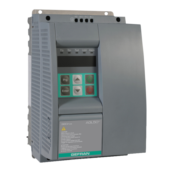
Drive Keypad Operation
Keypad Buttons and LED Indicators
Describes the function of each keypad button and the meaning of LED indicators.
Navigating the Drive Menu
Illustrates how to move through the drive's main menu structure.
Parameters Modification Procedure
Explains the procedure for scrolling and changing parameter values using the keypad.
Commissioning Suggestions
Setting Motor Parameters and Speed References
Guides on setting motor nameplate data and default speed levels.
Ramp Settings and Boost Adjustment
Advice on ramp settings, slowing-down distances, and manual boost adjustment.
Default Lift Configuration
Command Logic and Input Assignment
Explains command assignment to digital inputs and the logic for lift control.
Lift Sequence Control Signals
Details the function of Enable, Run Fwd/Rev, and Frequency Select signals.
Lift Sequence
Standard Lift Sequence Timing
Illustrates the timing of signals for a standard lift operation sequence.
Detailed Stopping Sequence
Shows timing diagrams for stopping sequences, including DC brake and normal stop.
Lift-Dedicated Digital Output Functions
Lists and describes programmable digital output functions useful for lift applications.
Ramp Function
Lift Ramp Profile and Space Calculation
Illustrates lift ramp profiles and how to calculate space for ramp compatibility.
Short Floor Function
Short Floor Detection and Sequence
Explains how the drive detects short floors and the associated sequence adjustments.
Startup Menu
Startup Menu Parameter Access
Describes parameter organization, access levels, and the STARTUP menu structure.
Menù Display
Display Parameter Descriptions (d.xxx)
Lists display parameters showing drive status, speed, current, voltage, and errors.
Troubleshooting
Drive Alarm Condition and Display
Explains how alarms are displayed on the keypad and acknowledged.
Alarm Reset Procedures
Details methods for resetting alarms via keypad, digital input, or autoreset.
List of Drive Alarm Events
Describes causes for all possible alarms with their codes and descriptions.
Parameter List
Startup and Core Configuration Parameters
Covers essential setup like voltage, frequency, motor data, and display settings.
Input/Output and Communication Parameters
Details digital/analog I/O, serial communication, and encoder configurations.
Performance, Ramp, and Control Parameters
Covers ramp functions, speed control, motor tuning, boost, slip, braking, and PID.
Hidden and Advanced Parameters
Lists parameters not accessible via keypad, for advanced configuration and diagnostics.
Need help?
Do you have a question about the 2075 and is the answer not in the manual?
Questions and answers