Table of Contents
Advertisement
Advertisement
Table of Contents

Related Manuals for Barco MVGD 1318 CR/ER


Summary of Contents for Barco MVGD 1318 CR/ER
- Page 1 MVGD 1318 CR&ER Installation & User Manual...
- Page 2 (This page intentionally left blank.) (This page intentionally left blank.)
-
Page 3: Table Of Contents
Table of Contents Table of Contents Preface ....................4 Safety Instructions................ 6 Explanation of symbols..............8 Overview.................... 10 Introduction ................10 Parts, controls and connectors........... 11 Installation ..................14 Display installation..............14 Attaching the display to an arm stand ........18 Operation ................... -
Page 4: Preface
BarcoView software products are the property of BarcoView. They are distributed under copyright by Barco N.V. or BarcoView, LLC., for use only under the specific terms of a software license agreement between Barco N.V. - Page 5 Preface interference, and (2) this device must accept any interference received, including interference that may cause undesired operation. NOTE: This equipment has been tested and found to comply with the limits for a Class B digital device, pursuant to Part 15 of the FCC Rules. These limits are designed to provide reasonable protection against harmful interference in a residential installation.
-
Page 6: Safety Instructions
Preface Safety Instructions General Recommendations Read the safety and operating instructions before operating the display. Retain safety and operating instructions for future reference. Adhere to all warnings on the display and in the operating instructions manual. Follow all instructions for operation and use. Electrical shock Type of protection (electrical): Class I equipment... - Page 7 Preface hospital-grade type plug 5-15P configuration for 120V application, or 6-15P for 240V application. • Do not overload wall outlets and extension cords as this may result in fire or electric shock. • Mains lead protection (U.S.: Power cord): Power cords should be routed so that they are not likely to be walked upon or pinched by items placed upon or against them, paying particular attention to cords at plugs and receptacles.
-
Page 8: Explanation Of Symbols
Preface This apparatus conforms to: CE0120, IEC 60601-1, UL 60601-1, IEC 60950-1, CAN/CSA C22.2 No. 601.01-M90 (c-UL) National Scandinavian Deviations for Cl. 1.7.2 : Finland: "Laite on liitettävä suojamaadoituskoskettimilla varustettuun pistorasiaan" Norway: "Apparatet må tilkoples jordet stikkontakt" Sweden: "Apparaten skall anslutas till jordat uttag" Explanation of symbols Symbols on the display and power supply On the display or power supply, you may find the following symbols:... - Page 9 Preface Indicates the USB connectors on the display Functional ground terminal Protective earth terminal Indicates the manufacturing date Indicates the temperature limitations for the display to operate within specs Indicates the display serial no. Consult the operating instructions Indicates this apparatus must not be thrown in the trash but must be recycled, according to the European WEEE (Waste Electrical and Electronic Equipment) directive...
-
Page 10: Overview
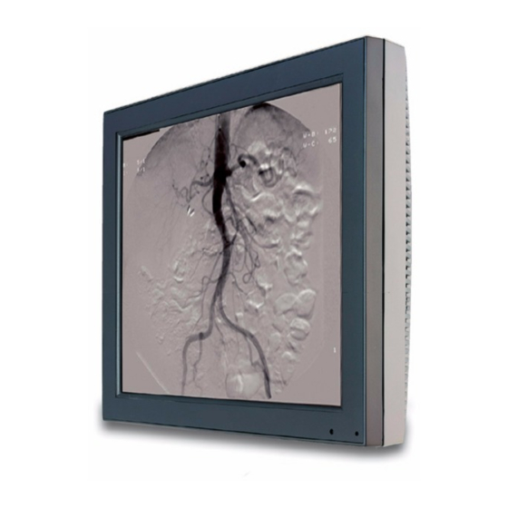
Introduction Thank you for choosing Barco. MVGD 1318 CR/ER display The MVGD 1318 CR/ER is a 18.1-inch grayscale LCD display with a native resolution of 1280 x 1024. Its high-brightness, combined with image crispness and excellent viewing angle, makes it an ideal solution for a multitude of medical applications and environments. -
Page 11: Parts, Controls And Connectors
Overview Parts, controls and connectors Front Figure 1 Ambient Light (ALC) sensor. When ALC is switched on, the display light output is adapted automatically, depending on the ambient light measured by the sensor. Power LED The LED is off when the display is disconnected from the power. The LED is also off when the LED function is disabled in the on- screen display (OSD). - Page 12 Overview Rear Figure 2 Connector compartment cover To get access to the connectors, remove the cover by pulling down the 2 clips at the top of the cover. Connectors Figure 3 DVI-I video input D-Sub 15 or VGA (analog) video input Analog video input (separate or composite) This is a monochrome video input Video amplitude: 500-950 mV...
- Page 13 Overview Composite or Horizontal Sync (CS/HS) input Amplitude: 500 mV to 5V Vertical Sync (VS) input Amplitude: 500 mV to 5V USB upstream port USB 1.1 standard is supported. Connect this connector to the PC USB bus if you wish to control the display via the USB bus.
-
Page 14: Installation
Installation Installation Precautions • Keep your original packaging. It is designed for this display and is the ideal protection during transport. • Avoid reflections in the flat panel to reduce eye strain. • Place the display on a strong and stable table or desk (desktop version). -
Page 15: Video Connection
Installation Video connection The display accepts 3 different video formats: DVI-I, VGA (analog) and BNC (analog, only for monochrome video signals). You can connect one or all of these inputs. If more than 1 input is connected you can switch inputs by using the display’s on-screen display. - Page 16 Installation Figure 6 Connect the other end of the VGA cable to the analog video output of the signal source. Note: If you connect an analog video signal, you may need to perform some image adjustments to obtain optimum image quality.
-
Page 17: Usb Connection
Installation 2) 3) 4) Figure 7 Note: If you connect an analog video signal, you may need to perform some image adjustments to obtain optimum image quality. Please refer to chapter “Operation”. USB connection The USB connection allows you to use the display as USB hub, to which you can connect USB devices, such as a keyboard, mouse or digital camera. -
Page 18: Attaching The Display To An Arm Stand
Installation Figure 8 Cable routing Routing the signal cables • Bind the cables in the connector compartment together with the cable tie inside the connector compartment. • Put the connector compartment cover back on the display. Pay attention that the signal cables are positioned under the bulge in the cover. - Page 19 Installation To attach the display to an arm stand: Attach the arm stand firmly to the panel using 4 screws M4 x 8 4 screws M4 x 8mm Figure 9...
-
Page 20: Operation
Operation Operation Operating precautions Continuous operation of the display with the same image may result in some image sticking on the LCD panel. Over 10 hours operation with the same image content is not recommended. Switching on DPMS on display and PC and activating a good screen saver may decrease the risk of image sticking (image retention). -
Page 21: About The On-Screen Display (Osd)
Operation About the On-Screen Display (OSD) There are two methods to control the display To control the display you can use: • Quick OSD: To quickly access the most important controls. • Extended OSD: To access all the display controls. The extended OSD can be used in two modes: standard and advanced (see further). - Page 22 Operation The possible Quick OSD menus are:: Brightness Contrast Input selection Luminance Horizontal scaling Scaling Information For more information about these menus, please refer to the chapter about the Extended OSD functions. About the Extended OSD The Extended OSD has a hierarchical tree structure, with several levels. The top level is the “Main Menu”.
- Page 23 Operation MVGD 1318 CR/ER MAIN MENU Autoset Video Contrast Video Brightness Luminance ADJUSTMENTS Adjustments Input Selection Auto Geometry Settings Phase Preset EXIT Information EXIT Main menu and submenu The content of the OSD depends on the selected video input: A number...
- Page 24 Operation MVGD 1318 CR/ER MVGD 1318 CR/ER MAIN MENU MAIN MENU Autoset Luminance Video Contrast Adjustments Video Brightness Input Selection Auto Luminance Settings Adjustments Information Input Selection Auto EXIT Settings Preset Information EXIT Main menu for analog video Main menu for digital video The extended OSD can be used in standard and advanced mode.
- Page 25 Operation MVGD 1318 CR/ER MAIN MENU Autoset Video Contrast Video Brightness Luminance ADJUSTMENTS Adjustments Input Selection Auto Geometry Settings Phase Preset EXIT Information EXIT Rotate the control wheel Press the control wheel To exit from a menu, rotate the control wheel to select EXIT.
-
Page 26: Adjustments For A Digital Video Signal
Operation How to save changes When you have changed something and you wish to exit from the main menu, the display asks if you wish to save the changes. Save Changes? Rotate the control wheel to select Yes (to save the changes) or No (if you do not wish to save the changes). - Page 27 Operation When do you need to use the Autoset function? • The first time you use the display with analog video connected. • After connecting or selecting another analog video source (e.g., changing the PC resolution). • In case you notice the image geometry or positioning is not as desired.
-
Page 28: Standard Osd Functions
Operation Standard OSD functions Main menu Name Description Present in DVI mode Autoset Allows to perform automatic image adjustments Video Contrast Adjust contrast of the image Video Brightness Adjust brightness of the image Luminance Adjust the target luminance to which the display will be stabilized. - Page 29 Operation The Autoset menu is not available in DVI mode. Name Description Full Autoset Perform all Autoset functions (below) one after another Automatic Gain Adjust the video levels (black and white) automatically Automatic Geometry Adjust the image geometry automatically. This function displays the complete active video in the center of the screen.
- Page 30 Operation • Automatic Phase: The image should contain sharp black-white transitions, like a line pattern or characters. • Automatic Gain: The image should contain parts that are completely black (0% video amplitude) and parts that are full white (100% video amplitude). Video Contrast This menu is not available in DVI mode.
- Page 31 Operation Luminance Name Description Luminance Target Manually adjust the luminance The calibrated luminance is indicated as 100% Luminance adjusts the overall luminance (light output) of the display. It does not affect the grayscales of the image on the screen. When Ambient Light Compensation (ALC) is switched on, the (manual) luminance adjustment will not work.
- Page 32 Operation Adjustments: Geometry Name Description Present in DVI mode Automatic This is the same function as in the Geometry Autoset menu. Please refer to the description of the Autoset functions above. After Automatic Geometry, the image is centered inside the active video window.
- Page 33 Operation Adjustments: Phase This menu is not available in DVI mode Name Description Automatic Phase This is the same function as in the Autoset menu Frequency Adjust the video sampling frequency manually. This is necessary when you notice abnor- mal vertical banding, which can be seen best on a dot on/dot off pattern.
- Page 34 Operation Input Selection Name Description Auto Automatically selects the input to which a video signal is connected. If more than one video signal is connected, priority is given to DVI. DVI-D Select the digital DVI input. Select the DB15 (VGA) input. Select the BNC input.
- Page 35 Operation This menu is not available in DVI mode. For more information about the Presets, please consult the Glossary section Name Description Find next preset Select another Preset from memory that matches the incoming video and sync sig- nals. The number displayed in the OSD is the number of the actual Preset's memory location.
- Page 36 Operation Information - General Information: Name Description Product The display type Serial No Indicates the display serial number SW Version Displays the current internal software ver- sion Display Lifetime Indicates the total time the display has been operating, including the time in stand-by Backlight Lifetime Indicates the total time the display has...
-
Page 37: Advanced Osd Functions
The functions described in this chapter are intended for trained service staff only! Improper use of these functions may cause the display to not function correctly. Barco cannot be held responsible for the results or damage caused by improper use of these functions. About the Advanced functions The advanced functions are extensions of the standard OSD. -
Page 38: Advanced Functions In The Adjustments Menu
Operation Advanced functions in the Adjustments menu Ambient Light Compensation Name Description Min ALC Contains two functions to set the mini- mum point of the ALC control system: Min Ambient Light: Enter the value (in Lux) of the darkest possible ambient light condition you are likely to work in. -
Page 39: Advanced Functions In The Settings Menu
Operation Advanced functions in the Settings menu Display Function See the Glossary section for more information about display functions. The display contains a number of factory-defined lookup tables (LUTs) to define the display (transfer) function. Name Description DICOM Select a DICOM display function for most medical viewing applications. - Page 40 Operation Standard input mode Name Description RGB->RGB The R video signal drives the R sub-pix- els, the G video signal drives the G sub- pixels and the B video signal drives the B sub-pixels. This is the preferred set- ting for color display controllers. RGB->Y The RGB video signals from the imaging board are calculated and transformed...
- Page 41 Operation Extended input mode Name Description RBG->Y The RGB video signals from the imag- ing board are calculated and trans- formed into a single luminance value according to the formula 0.3R + 0.59B + 0.11G. This single luminance signal drives the RGB sub-pixels of the panel equally.
-
Page 42: Advanced Functions In The Presets Menu
Operation OSD position With the OSD function you can select where on the screen the OSD menu text will appear. You can select between center position, top left, top right, bottom left or bottom right. Quick OSD menu In this submenu from the Settings menu, you can determine which menus will appear in the Quick OSD menu. -
Page 43: Locking And Unlocking User Controls
Operation Service Service information is a submenu from General Information, containing the following items: Name Description Display Name The display type Display Ser No Indicates the display serial number Display Stock No Indicates the display order number Panel Indicates the flat panel serial number Panel Prod Date Indicates the flat panel production date Firmware... - Page 44 Operation • switch the display in stand-by mode To disable user controls: When the OSD is not on the screen, rotate the control wheel to display the Extended OSD. The Main Menu appears. Rotate the control wheel to select Exit. Press and hold the control wheel until the Advanced Main Menu appears.
-
Page 45: Cleaning
*(Lye is a strong caustic alkaline solution of potassium salts.) Panel Important: We recommend to let this cleaning procedure be done in a Barco service center. If not, you must perform the cleaning in a clean and dust-free environment. If there are dust particles on the LCD panel, blow them away by using a dust remover. - Page 46 Cleaning acts like compressed air for a quick and safe removal of dust particles and other dry contaminants on the surface of the lcd panel or the glass panel. Attention: The dust remover contains a liquid gas. If you shake the can or move the can too fast while spraying, you may blow drops of liquid on the panel surface! If this is the case, clean the panel as described below.
-
Page 47: Troubleshooting
Troubleshooting Troubleshooting General tips • If one display from a multi-head system exhibits problems, try to eliminate the problem by switching video cables or power supplies. In that way you can find out if the problem resides in the display or not. Problems and solutions Problem description Possible tests or solutions... - Page 48 Troubleshooting Problem description Possible tests or solutions Nothing happens when • The User Controls may be disabled. you press or rotate the Please read the paragraph about the control wheel “User Controls” function. The image is non-pro- • Select another resolution in the portionally spread out Windows “Display Properties”...
-
Page 49: Technical Information
Technical Information Technical Information Technical specifications MVGD 1318: Item Specification Picture panel 18.1-inch diagonal viewable screen TFT (thin film transistor) active matrix, gray- scale liquid crystal display Resolution Native: 1280 x 1024 Display area (H x V) 359 x 287.2 (mm) Viewing angle Vertical: 170º... - Page 50 Technical Information Item Specification Power consumption 64 watts (max., at 90 VAC, maximum backlight, USB load) Dimensions 432 x 362.2 x 107 mm (W x H x D) Net weight 8.1 kg Operating Temperature MVGD 1318 ER: 0°C to 35°C, 15°C to 35°C within specs MVGD 1318 CR: 0°C to 40°C, 15°C to 35°C within specs Storage Temperature...
-
Page 51: Connector Pin Assignments
Technical Information Connector pin assignments DVI connector: C1 C2 Figure 11: DVI-I connector pin layout Pin no. Signal Pin no. Signal TMDS DATA 2- +5V 500mA max. TMDS DATA 2+ TMDS DATA 0- TMDS DATA 0+ DDC CLOCK DDC DATA Analog VS TMDS CLOCK- TMDS DATA 1-... -
Page 52: Glossary
Technical Information D-Sub 15 connector: Figure 12: D-Sub 15 pin layout Pin no. Signal Pin no. Signal Red in DDC 5V IN Green in VGA PRES Blue in DDC SDA HS IN VS IN DDC SCL Glossary Calibration Each display is calibrated in the factory before it is sent to the customer. After this calibration, black and white luminance are set to the ideal level. - Page 53 Technical Information Display Function A Display Function describes how a display device converts the video signals at the inputs into light. In the context of a medical viewing station, a display device is the combination of display controller (graphics board) and display. The display function is a graph that shows how the light from the display panel evolves from minimum to maximum luminance while the data levels at the input of the display controller go from 0 to maximum.
-
Page 54: Warranty Statement
Warranty Statement Warranty Statement ARTICLE 1: SERVICES BarcoView warrants that the equipment will be free of defects in workmanship or material for the warranty period. Notwithstanding the provisions of clause 2, repair and replacement of defects in material and/or workmanship under this warranty shall be accomplished in our works in the following manner: 1.1 The Customer, upon the occurrence of any equipment failure, shall contact BarcoView Customer Support Center (or an authorized service... - Page 55 Warranty Statement ARTICLE 2: ITEMS EXCLUDED FROM WARRANTY The warranty described herein shall not include the following: 2.1 Any hardware or software item procured from a source other than BarcoView or their official agent or distributor and integrated by Customer or a third party into BarcoView supplied equipment. 2.2 Any host configuration not explicitly supported by BarcoView.
- Page 56 Warranty Statement agents, employees, or representatives, shall be borne by the Customer at its additional cost and expense. 3.3 The customer is responsible for installing the BarcoView equipment in an environment for which it was intended. If there is an indication that the equipment was used - even temporary - outside its specifications, BarcoView is entitled not to perform warranty repairs and terminate the warranty agreement.
- Page 57 Warranty Statement this agreement is impeded by reason of force majeure. For the purposes of this clause the expression “force majeure” means, but shall not be limited to, industrial dispute, fire, mobilization, requisition, embargo, currency transfer prohibitions, insurrection, lack of means of transport, restrictions of the use of energy, and generally any circumstances which are beyond the control of the parties and hinder performance by one party of his obligations.
- Page 58 Warranty Statement...
- Page 59 K5904082-01 October 2006 www.barco.com...
Need help?
Do you have a question about the MVGD 1318 CR/ER and is the answer not in the manual?
Questions and answers