Barco DML-1200 User Manual
Hide thumbs
Also See for DML-1200:
- User manual (177 pages) ,
- Specifications (2 pages) ,
- User manual (163 pages)
Table of Contents
Advertisement
Quick Links
Download this manual
See also:
User Manual
Advertisement
Table of Contents

Related Manuals for Barco DML-1200


Summary of Contents for Barco DML-1200
- Page 1 DML-1200 User guide R9050120 R59770208/00 01/10/2008...
- Page 2 Barco nv Media & Entertainment Division Noordlaan 5, B-8520 Kuurne Phone: +32 56.36.89.70 Fax: +32 56.36.883.86 E-mail: sales.events@barco.com Visit us at the web: www.barco.com Printed in Belgium...
- Page 3 Changes Barco provides this manual ’as is’ without warranty of any kind, either expressed or implied, including but not limited to the implied war- ranties or merchantability and fitness for a particular purpose. Barco may make improvements and/or changes to the product(s) and/or the program(s) described in this publication at any time without notice.
-
Page 5: Table Of Contents
10.6 CTO (Color temperature origin) ..................... 52 R59770208 DML-1200 01/10/2008... - Page 6 Index........................87 R59770208 DML-1200 01/10/2008...
-
Page 7: Safety
This will prevent damage to the device due to lightning and AC power-line surges. • Do not guide the power cord over the base unit of the device. Ensure that the power cord cannot make contact with moving head. R59770208 DML-1200 01/10/2008... - Page 8 Ensure that nothing can be spilled on, or dropped inside the device. If this does happen, switch off and unplug the mains supply immediately. Do not operate the device again until it has been checked by qualified service technicians. R59770208 DML-1200 01/10/2008...
- Page 9 Refer all servicing to qualified service personnel. • Fence off a restricted area of at least 3 meters around the projector using an eye-catching fence and “KEEP OUT” signs. This to prevent unauthorized persons coming near the projector during servicing. R59770208 DML-1200 01/10/2008...
-
Page 10: Important Warnings Concerning Dml Flight Cases
If the product exhibits a distinct change in performance, indicating a need for service. • Replacement parts: When replacement parts are required, be sure the service technician has used original Barco replace- ment parts. Unauthorized substitutions may result in degraded performance and reliability, fire, electric shock or other hazards. - Page 11 Disposal options for mercury-containing lamps • Recycle through a municipal or solid waste district household hazardous waste collection program in accordance with local regulations. • Direct shipment to lamp recycler • Shipment through a hazardous waste transporter R59770208 DML-1200 01/10/2008...
- Page 12 1. Safety R59770208 DML-1200 01/10/2008...
-
Page 13: General
Device weight Do not underestimate the weight of one DML-1200, which is about ±75 kg (±166 lb.). Be sure that the table or truss installation on which the device(s) has to be installed is capable of handling five (5) times the complete load of the complete system. - Page 14 3. Take off the cover with the wheels. Image 2-2 Open flight case 4. Take out the device by its carrying handles and place it on its foot. Caution: Lift it up with 2 persons while a 3rd person pushes away the flight case. R59770208 DML-1200 01/10/2008...
- Page 15 2. General Image 2-3 AUTION Never use the head as carrying handle to lift up the DML-1200. For rigged operation 1. Leave the flight case on its wheels and open the 6 locks. Image 2-4 Open flight case 2. Take off the L-shaped cover.
-
Page 16: Projector Air Inlets And Outlets
Air flow base The DML-1200 has an air inlet at the lens side of the head and an air outlet at the back side of the head. The base has an air inlet at the back side and an air outlet at the right side and left side. -
Page 17: Physical Installation
Truss mounting of the DML-1200 Pan and tilt locking AUTION Unlock the tilt and pan lock before operating the DML-1200 ! Tilt lock The projector head can be locked each 45° starting from its packing position (7 lock positions). Image 3-1 Different lock positions To lock the head, turn it in one of the 7 possible lock positions and press the red button on the rotation axis (F). - Page 18 To lock the yoke, rotate it in one of the 4 possible positions and then move the handle from the upper position (U) to the lower positions (L). Image 3-4 To unlock the yoke, move the handle from the lower position (L) to the upper position (U). R59770208 DML-1200 01/10/2008...
-
Page 19: Mounting The Dml-1200 Upright
How to mount To mount the DML-1200 upright, place the device on a sturdy, stable surface that will support more than 75 kg (165.4 lbs). If the surface is above floor height, use safety cables to secure the device to the surface. - Page 20 1. Measure the distance, center tube as reference, between the two used support bars of the truss. X mm Image 3-7 2. Push the rigging point downwards and slide it at the same time to its place, according the measured distance. Release the rigging point. R59770208 DML-1200 01/10/2008...
- Page 21 4. Place all four rigging clamps in open position. 5. Place the device under the truss installation and lower the truss until the support bars of the truss are nearby the rigging clamps mounted on the device. R59770208 DML-1200 01/10/2008...
- Page 22 Stretch the security cable completely. If necessary, turn the security cable a few times around the truss before closing the con- nection so that the cable is stretched as much as possible. Image 3-11 Mount safety cable 8. Lift up the truss with attached device to the desired height. R59770208 DML-1200 01/10/2008...
-
Page 23: Connections
Homing the device When the DML-1200 is connected to an appropriately-rated power source, it automatically begins a homing procedure to verify that the major functions of the device are oriented properly. This homing procedure includes movements of the projector head and yoke. -
Page 24: Input Connections
G(s) : 1Vpp ±3dB (0,7Vpp G + 0,3Vpp Sync) 75 Ohm termination. B : 0,7Vpp ±3dB 75 Ohm termination. SDI / HD-SDI, specifications • 1 input (BNC), 1 active loop-through output (BNC) • 10 bit/color • SDI: 525/625 interlaced. • Coax (75 Ohm). R59770208 DML-1200 01/10/2008... -
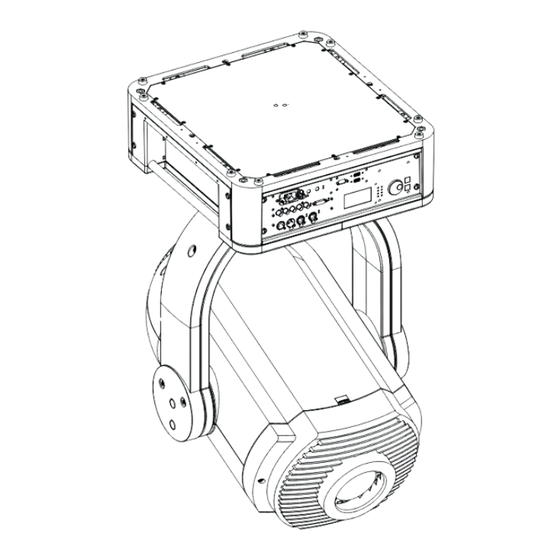
Page 25: Communication Connections
HDCP DVI ENTER LMP 1 LMP 2 10 / 100 / 1000 LMP 3 LMP 4 EXIT Image 4-3 Communications DMX512 data in, data out Ethernet connection LCD communication display Function buttons and jog dial USB inputs R59770208 DML-1200 01/10/2008... -
Page 26: Usb Port
DMX512 standard. You can use the DMX input port (A) to connect a DMX device or lighting console. This way you can control the DML-1200 from that lighting console. The DMX output port (G) can be connected to the next device in the daisy chain. The DMX output port is a passive loop through and is functional even when the device is not powered. -
Page 27: Linking Dml-1200'S
LEDs are only active when the LCD panel is activated or when an activation command is sent via Projector Toolset. Linking DML-1200’s Standard DMX linking The number of devices on a link will be determined by the combined number of channels required by all devices. One link (universe) contains 512 channels. R59770208 DML-1200 01/10/2008... - Page 28 DMX linking Therefore, one DMX universe can contain up to 4 DML-1200 devices with a Media Player and up to 10 devices without Media Player. To control a DML-1200 without Media Player, 51 DMX channel are necessary. When the Media Player is available, 128 channels are required.
- Page 29 4. Connections DMX Universe 2 DMX Universe 1 Ethernet ArtNet Ethernet cable Image 4-5 DMX on Ethernet Alternative setup: DMX Universe 2 DMX Universe 1 ArtNet Ethernet cable Image 4-6 DMX on Ethernet, alternative setup R59770208 DML-1200 01/10/2008...
- Page 30 4. Connections R59770208 DML-1200 01/10/2008...
-
Page 31: Start Up Of The Adjustment Mode
Both bottom lines on the display are used to indicate the last error or warning which has occurred. The first line of these two indicates the status, warning or error and the second line gives a description of the warning or error. To see an overview of all warnings and errors, see "Error list", page 77. R59770208 DML-1200 01/10/2008... - Page 32 5. Start up of the Adjustment mode R59770208 DML-1200 01/10/2008...
-
Page 33: Input Menu
2. Turn the jog dial to select Input and press Enter. The input selection menu opens. 3. Turn the jog dial until the second page of the input menu is displayed and turn further to select Auto image alignment and press Enter. R59770208 DML-1200 01/10/2008... -
Page 34: Reset To Factory Presets
3. Turn the jog dial until the second page of the input menu is displayed and turn further to select Reset to factory presets and press Enter. A reset is executed. Image 6-7 Image 6-8 Image 6-6 R59770208 DML-1200 01/10/2008... -
Page 35: Lamp Menu
These parameters are useful when calling for a service intervention. How to display 1. Press Enter to start up the main menu. 2. Turn the jog dial to select Lamp and press Enter. 3. Turn the jog dial to select Identification. and press Enter. R59770208 DML-1200 01/10/2008... -
Page 36: Status And Run Time Overview Lamps
2. Turn the jog dial to select Lamp and press Enter. 3. Turn the jog dial to select Overview and press Enter. The lamp overview menu appears. The status and the run time for each lamp is indicated. Image 7-6 Image 7-5 Image 7-4 R59770208 DML-1200 01/10/2008... -
Page 37: Control Menu
Startup What happens When the device is started up, lamps start up and waits until new commands are sent to the device. R59770208 DML-1200 01/10/2008... -
Page 38: Standby
What can be done ? Within the DML-1200 a demo run is programmed. When the demo mode is activated, the demo run starts with an interval of x seconds. The number of times the demo run has been started is indicated in Demo cycles. -
Page 39: Dmx Data
1. Press Enter to start up the main menu. 2. Turn the jog dial to select Control and press Enter. 3. Turn the jog dial to select DMX data and press Enter. 4. Turn the jog dial to select a DMX channel and press Enter. R59770208 DML-1200 01/10/2008... -
Page 40: Dmx Address
What can be done ? One DMX universe can contain up to 4 DML-1200 devices with a Media Player and up to 10 devices without Media Player. If you have more devices to control, group them in different DMX universes. -
Page 41: Media Player On - Off
3. Turn the jog dial until the second page of the control menu is displayed and turn further to select LCD contrast and press Enter. 4. Turn the jog dial to adjust the local contrast and press Enter. R59770208 DML-1200 01/10/2008... -
Page 42: Pan And Tilt Encoder
8.10 Pan and Tilt encoder What is possible ? When the DML-1200 is panned or tilted due to an external intervention, e.g. a push, it can always return to its original position when pan and or tilt encoder is enabled. -
Page 43: Network
3. Turn the jog dial until the second page of the control menu is displayed and turn further to select Network and press Enter. 4. Turn the jog dial to select the desired network setting, DHCP, Art-Net or preset. Image 8-29 Image 8-30 Image 8-28 R59770208 DML-1200 01/10/2008... - Page 44 8. Control menu R59770208 DML-1200 01/10/2008...
-
Page 45: Service Menu
Installed software package How to consult 1. Press Enter to start up the main menu. 2. Turn the jog dial to select Service and press Enter. 3. Turn the jog dial to select Identification and press Enter R59770208 DML-1200 01/10/2008... -
Page 46: Diagnosis
The first page of the version table is displayed. As there are more items than space available on the LCD, when turning the jog dial further than the last item a new page will be displayed. Image 9-6 Image 9-5 Image 9-4 R59770208 DML-1200 01/10/2008... -
Page 47: Voltages
1. Press Enter to start up the main menu. 2. Turn the jog dial to select Service and press Enter. 3. Turn the jog dial to select Diagnosis and press Enter. 4. Turn the jog dial to select Temperatures and press Enter. R59770208 DML-1200 01/10/2008... -
Page 48: Fan Speeds
The first page of the fan speeds table is displayed. As there are more items than space available on the LCD, when turning the jog dial further than the last item a new page will be displayed. Image 9-18 Image 9-17 Image 9-16 R59770208 DML-1200 01/10/2008... -
Page 49: Device Status
A full logging can be requested since the device is electrically connected. This logging contains info lines, warnings and errors. An info, warning or error is always displayed in two lines. The structure of the logging is as follow: R59770208 DML-1200 01/10/2008... -
Page 50: Service Patterns
The first page of the error logging table is displayed. If there are more error than space available on the LCD, when turning the jog dial further than the last error a new page will be displayed. Image 9-26 Image 9-25 Image 9-24 Image 9-27 Service patterns What is possible ? Different patterns are available for service purposes. R59770208 DML-1200 01/10/2008... -
Page 51: Calibration
The index delay value should be adjusted so that the phase of the color wheel is correctly aligned. When correctly align a mono- chrome red image e.g. will be correctly displayed. When there is a misalignment, this image will show color distortion (discoloration) at the top and the bottom of the image. This setting is normally factory aligned. R59770208 DML-1200 01/10/2008... -
Page 52: Aperture Calibration
4. Turn the jog dial over the last item to open the second page. 5. Turn the jog dial to select Aperture cal and press Enter. 6. Turn the jog dial to change the current value and press Enter. R59770208 DML-1200 01/10/2008... -
Page 53: Device Calibration
4. Turn the jog dial to select an item or turn the jog dial over the last item to open the second menu and select an item and press Enter. 5. Turn the jog dial to change the current value and press Enter. Image 9-40 Image 9-39 Image 9-41 R59770208 DML-1200 01/10/2008... - Page 54 9. Service menu R59770208 DML-1200 01/10/2008...
-
Page 55: Moving Light Control Via Dmx
0 - 255 128 Changes from close to distant focus 10.4 Shutter - Strobe Channel 8 Value Default Action 0 - 31 Shutter open 32 - 47 Strobe from slow to fast 48 - 255 For future expansion R59770208 DML-1200 01/10/2008... -
Page 56: Cyan - Magenta - Yellow
Adjustments are done between 3000°K (DMX value zero) and 6200°K (DMX value 255).. 10.7 Mode selection About mode selection The DML-1200 can be used in: • Light mode : circular light beam that can change in color (monochrome video). •... -
Page 57: Control Channel
48 - 63 Homing without pan and tilt 64 - 79 Homing, pan and tilt only 80 - 95 Homing CMY only 96 - 127 Lamp on 128 - 159 Lamp off 160 - 255 For future expansion R59770208 DML-1200 01/10/2008... - Page 58 10. Moving light control via DMX R59770208 DML-1200 01/10/2008...
-
Page 59: Image Control Via Dmx
Channel 19 adjusts the saturation between 0 and 100% when sending a value between 0 and 255. 11.4 Orientation Channel 20 Value Default Action 0 - 31 Normal 32 - 63 Mirror 64 - 95 Flip 96 -127 Flip + Mirror 128 - 255 For future expansion R59770208 DML-1200 01/10/2008... -
Page 60: Blanking
Image 11-2 Blanking adjustment Top blanking Bottom blanking Left blanking Right blanking Channels Channel Description Value Default Action Blanking left Coarse 0 - 255 0 Adjust the left blanking 0 - 255 0 Blanking left Fine R59770208 DML-1200 01/10/2008... -
Page 61: Soft Edge
Image warping is the process of digitally manipulating an image to compensate for the distortion of the screen. Consequently, it can also be used to generate an image with irregular shape. While an image can be transformed in various ways, pure warping doesn’t affect the colors. Some examples of warped images, using the warp geometry settings: R59770208 DML-1200 01/10/2008... - Page 62 Load warp file 14 120 - 127 Load warp file 15 128 - 135 Load warp parameters 136 - 247 For future expansion 248 - 255 Warp enabled Channel 36 and 37 Warp parameters. Reserved for future expansion. R59770208 DML-1200 01/10/2008...
-
Page 63: Maintenance
Do not use liquid cleaners on the cloth as doing so will contaminate the cloth. Other lenses can also be cleaned safely with this Toraysee cloth. 12.2 Cleaning the exterior of the DML-1200 How to clean the exterior 1. Unplug the power cord. - Page 64 12. Maintenance R59770208 DML-1200 01/10/2008...
-
Page 65: Servicing
Removal of a lamp unit • Mounting a new lamp unit AUTION All HEPA filters of the DML-1200 must be replaced on a regular basis, depending on the environ- ment conditions of the device. 13.1 Removal of the front cover Necessary tools... -
Page 66: Opening The Top Cover On The Lamp Units Side
13.2 Opening the top cover on the lamp units side Necessary tools Flat screwdriver How to open 1. Stand on the side of the locking buttons and turn the head so that the lens points to the right. R59770208 DML-1200 01/10/2008... - Page 67 Image 13-3 Filter location Locking of the head Lens side The upper cover can now be opened. 2. Lock the head. 3. Loosen both captive screws. Image 13-4 Captive screws top cover 4. Lift up the top cover. R59770208 DML-1200 01/10/2008...
-
Page 68: Replacement Of The Dust Filters On The Front Side
2. Remove the front cover, see "Removal of the front cover", page 61. 3. Remove the HEPA filter on the front side by pulling the spring clamp (A) on the upper side away from the filter and then pivot the filter a little (B) and take it out (C). R59770208 DML-1200 01/10/2008... -
Page 69: Replacement Of The Dust Filter At The Inside Of The Head
1. Unplug the power cord from the wall outlet. 2. Open the top cover on the lamp units side, see "Opening the top cover on the lamp units side", page 62. 3. Pull out the HEPA filter. R59770208 DML-1200 01/10/2008... -
Page 70: Replacement Of The Dust Filter In The Base
13.5 Replacement of the dust filter in the base Necessary tools Flat screwdriver Necessary parts New HEPA filter How to replace 1. Loosen the 4 captive screws. Image 13-8 Captive screws 2. Take off the side panel. R59770208 DML-1200 01/10/2008... -
Page 71: Removal Of A Lamp Unit
The device head contains 4 lamps, each of them in a separate lamp house. Each lamp can be individually replaced by a spare lamp. Each lamp position has a number. That number is also used in the software to identify the parameters of the corresponding lamp. R59770208 DML-1200 01/10/2008... - Page 72 2. Open the top cover on the lamp units side, see "Opening the top cover on the lamp units side", page 62. 3. Unplug the cable of the lamp which must be removed. Image 13-12 Lamp cables, connection 4. Pull up the fixation handle and rotate it fully upwards. R59770208 DML-1200 01/10/2008...
-
Page 73: Mounting A New Lamp Unit
13.7 Mounting a new lamp unit About the lamp unit All four lamp units are equal. A spare lamp can be inserted in any position without problems. ARNING This procedure may only be performed by qualified technical service personnel. R59770208 DML-1200 01/10/2008... - Page 74 2. Rotate the fixation handle and close it. Push until it clicks. 3. Insert the cable connector into the lamp unit socket. Starting up the lamps is only possible if all lamps are correctly mounted in the projector head. R59770208 DML-1200 01/10/2008...
-
Page 75: Dmx Chart
128 - 159 Lamp off 160 - 255 For future expansion A.2 DMX chart, Image Overview Chan- Type Function Value Default Action 0 - 31 No source selected Source select 32 - 63 RGBHW selected 2. x indicates XFade R59770208 DML-1200 01/10/2008... - Page 76 Load warp file 7 64 - 71 Load warp file 8 72 - 79 Load warp file 9 80 - 87 Load warp file 10 88 - 95 Load warp file 11 96 - 103 Load warp file 12 R59770208 DML-1200 01/10/2008...
- Page 77 For future expansion For future expansion For future expansion For future expansion For future expansion For future expansion For future expansion For future expansion For future expansion For future expansion For future expansion For future expansion R59770208 DML-1200 01/10/2008...
- Page 78 A. DMX chart R59770208 DML-1200 01/10/2008...
-
Page 79: Dimensions
B. Dimensions B. DIMENSIONS Overview • Dimensions of the DML-1200 • Dimensions flight case B.1 Dimensions of the DML-1200 Dimensions 209,25 109,25 109,25 M10 (8x) M10 (4x) 469,9 Image B-1 Dimensions given in millimeters R59770208 DML-1200 01/10/2008... -
Page 80: Dimensions Flight Case
B. Dimensions Image B-2 Dimensions, rotation B.2 Dimensions flight case Dimensions Image B-3 Dimensions in millimeters R59770208 DML-1200 01/10/2008... -
Page 81: Troubleshooting
Fan outlet B low Warning/Error If problem persists, call a qualified service technician Fan outlet B high Warning/Error If problem persists, call a qualified service technician Fan power supp A low Warning/Error If problem persists, call a qualified service technician R59770208 DML-1200 01/10/2008... - Page 82 Call a qualified service technician FCB I2C Warning If problem persists, call a qualified service technician Warning FCB parameters If problem persists, call a qualified service technician FCB monitoring Warning If problem persists, call a qualified service technician R59770208 DML-1200 01/10/2008...
- Page 83 C. Troubleshooting Description Type Action Housing switch open Warning/Error Close housing completely. If problem persists, call a qualified service technician Undefined Warning/Error If problem persists, call a qualified service technician R59770208 DML-1200 01/10/2008...
- Page 84 C. Troubleshooting R59770208 DML-1200 01/10/2008...
-
Page 85: Specifications
D. Specifications D. SPECIFICATIONS D.1 Specifications of the DML-1200 Overview AC power 200 - 240 V, 10 A, 50-60 Hz, input via 2m cable without connector Blanking horizontal & vertical, controlled over DMX Color change time 0.3 second, or as timed by control console Color Reproduction System substractive color mix (cyan, magenta, yellow) with dichroic filters... - Page 86 D. Specifications R59770208 DML-1200 01/10/2008...
-
Page 87: Order Info
This list contains only customer serviceable spare parts. Description Order info R98610206 Dust filter kit, 6 pack R986102012 Dust filter kit, 12 pack R9861030 Lamp kit, single lamp R9861040 Lamp kit, two lamps R9861050 Lamp kit, four lamps R59770208 DML-1200 01/10/2008... - Page 88 E. Order info R59770208 DML-1200 01/10/2008...
-
Page 89: Glossary
Glossary GLOSSARY DMX-512 Lighting protocol over RS-485 interface. Carries information of 512 channels from a lighting controller to lighting devices. Standardized by USITT. HEPA High Efficiency Particulate Absorbing R59770208 DML-1200 01/10/2008... - Page 90 Glossary R59770208 DML-1200 01/10/2008...
-
Page 91: Index
Cyan - Magenta - Yellow Intensity Iris Mode selection Error list Optical focus Ethernet Optical zoom Shutter - Strobe Tilt Front cover Removal Order info Spare parts General Guidelines Recycling Lamp Prevent 3–5 Battery explosion Device damage Electrical shock R59770208 DML-1200 01/10/2008... - Page 92 Restricted access location Base stand operation Servicing USB port Service 41–49 Calibration 47–49 Aperture calibration Device calibration Warning Index delay Restricted access location Diagnosis Warnings Version table Cooling liquid circuit Diagnostics 43–45 Mercury vapor warnings Device status Error logging R59770208 DML-1200 01/10/2008...
- Page 93 Revision Sheet Barco nv Media & Entertainment Division/Documentation Noordlaan 5, B-8520 Kuurne Phone: +32 56.36.89.70, Fax: +32 56.36.88.24 E-mail: service.mne@barco.com, Web: www.barco.com From: Date: Please correct the following points in this documentation (R59770208/00): page wrong correct R59770208 DML-1200 01/10/2008...
Need help?
Do you have a question about the DML-1200 and is the answer not in the manual?
Questions and answers