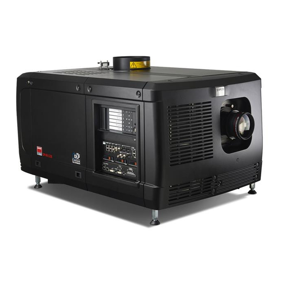
Barco DP2K-23B Installation Manual
Hide thumbs
Also See for DP2K-23B:
- Specifications (2 pages) ,
- Installation manual (125 pages) ,
- User and installation manual (202 pages)
Table of Contents
Advertisement
Quick Links
Advertisement
Table of Contents

Related Manuals for Barco DP2K-23B


Summary of Contents for Barco DP2K-23B
- Page 1 DP2K-23B Installation manual R59770495/00 30/04/2010...
- Page 2 Barco Inc. Media and Entertainment Division 11101 Trade Center Drive, Rancho Cordova, California 95670, USA Phone: +1 916 859-2500 Fax: +1 916 859-2515 E-mail: folsomsales@barco.com Visit us at the web: www.barco.com Barco nv Media & Entertainment Division Noordlaan 5, B-8520 Kuurne Phone: +32 56.36.82.11...
-
Page 3: Disposal Information
GNU-GPL code If you would like a copy of the GPL source code contained in this product shipped to you on CD, please contact Barco. The cost of preparing and mailing a CD will be charged. -
Page 4: Software License Agreement
This software and the accompanying files are sold “as is” and without warranties as to performance or merchantability or any other war- ranties whether expressed or implied. In no event shall Barco be liable for damage of any kind, loss of data, loss of profits, business interruption or other pecuniary loss arising directly or indirectly. - Page 5 Projector 零部件名稱 有毒有害物質或元素 铅(Pb) 镉(Cd 多 溴 二 苯 醚 汞(Hg) 六价铬(Cr6+) 多溴联苯(PBB) (PBDE) 金屬機構件 塑膠機構件 电路板组件* 燈泡 電源模組 电源线 外部信号连接线 風扇 散熱模組 (金屬部 分) 讀卡器 喇叭 (電路板組件 除外) 附電池遙控器 (電 路板組件除外) *: 电路板组件包括印刷电路板及其构成的零部件,如电阻、电容、集成电路、连接器等 ○:表示该有毒有害物质在该部件所有均质材料中的含量均在《电子信息产品中有毒有害物质的限量要求标准》规定的限量要求以下 ×:表示该有毒有害物质至少在该部件的某一均质材料中的含量超出《电子信息产品中有毒有害物质的限量要求标准》规定的限量要求;但 是上表中打“×”的部件,其含量超出是因为目前业界还没有成熟的可替代的技术,且符合歐盟RoHS指令的排外條款及電池指令...
-
Page 7: Table Of Contents
11.3 Cleaning the lens ........................108 R59770495 DP2K-23B 30/04/2010... - Page 8 Index........................129 R59770495 DP2K-23B 30/04/2010...
-
Page 9: Safety
1. Safety 1. SAFETY Overview • General considerations • Important safety instructions R59770495 DP2K-23B 30/04/2010... -
Page 10: General Considerations
Restricted access location The DP2K-23B digital projector may only be installed in a restricted access location, due to the temperature rise of parts of the equipment (air outlet). The definition of a “restricted access location" is a location for equipment where both of following paragraphs apply: •... -
Page 11: Important Safety Instructions
Lightning - For added protection for this video product during a lightning storm, or when it is left unattended and unused for long periods of time, remove all power from the projector. This will prevent damage to the projector due to lightning and AC power-line surges. R59770495 DP2K-23B 30/04/2010... - Page 12 fire extinguishers. Never use water on an electrical fire. Always have service performed on this projector by authorized Barco service personnel. Always insist on genuine Barco replacement parts. Never use non-Barco replacement parts as they may degrade the safety of this projector.
- Page 13 If the product exhibits a distinct change in performance, indicating a need for service. • Replacement parts: When replacement parts are required, be sure the service technician has used original Barco replacement parts or authorized replacement parts which have the same characteristics as the Barco original part. Unauthorized substitu- tions may result in degraded performance and reliability, fire, electric shock or other hazards.
- Page 14 Danger of explosion if battery is incorrectly installed. • Replace only with the same or equivalent type recommended by the manufacturer. • For disposal of used batteries, always consult federal, state, local and provincial hazardous waste disposal rules and regulations to ensure proper disposal. R59770495 DP2K-23B 30/04/2010...
-
Page 15: General
2. GENERAL About this chapter Read this chapter before installing your DP2K-23B digital projector. It contains important information concerning installation re- quirements for the DP2K-23B digital projector, such as minimum and maximum allowed ambient temperature, humidity conditions, required safety area around the installed projector, required power net, etc. -
Page 16: Installation Requirements
/min (350 CFM) measured at the exhaust output of the projector. Main Power requirements The DP2K-23B operates from a nominal mono phase power net with a separate earth ground PE. The DP2K-23B requires 200-240 VAC, 50-60Hz, 30A at 200 VAC with a separate earth ground PE. -
Page 17: Projector Weight
Projector weight Do not underestimate the weight of the Barco DP2K-23B digital projector. The projector weights about ±133 kg (±293 lb.) without lens. Be sure that the pedestal on which the projector has to be installed is capable of handling five (5) times the complete load of the system. -
Page 18: Unpacking The Projector
1. Loosen the banding by pulling the free end of the banding loop in the clip. Take off the box cover. Image 2-1 Open banding 2. Open the box. Take out the small box between the outer and inner box containing the manuals. Remove the outer carton box R59770495 DP2K-23B 30/04/2010... - Page 19 3. Remove the inner carton box. Image 2-3 Remove inner carton 4. Loosen the banding by pulling the free end of the banding loop in the clip. Take off the upper carton plate (1) Remove from the wooden pallet (2) R59770495 DP2K-23B 30/04/2010...
- Page 20 2. General Image 2-4 Remove wooden pallet 5. Take the projector from the wooden board by gripping the bottom of the projector and place the projector on the pedestal. Image 2-5 Remove projector R59770495 DP2K-23B 30/04/2010...
-
Page 21: Initial Inspection
This check should confirm that there are no broken knobs or connectors, that the cabinet and panel surfaces are free of dents and scratches, and that the operating panel is not scratched or cracked. The Barco Sales and Service office should be notified as soon as possible if this is not the case. -
Page 22: Installation Process Overview
After you have unpacked and checked the projector, you can start with the installation process of your DP2K-23B digital projector. This chapter gives you an overview of all the different stages in the installation process which you have to follow to set your DP2K-23B digital projector up and running. -
Page 23: Physical Installation
About this chapter This chapter describes how the mechanical and electrical set up of the projector has to be done. Overview • Positioning the DP2K-23B at port window • Installation of the exhaust system • Access to the power connection •... -
Page 24: Positioning The Dp2K-23B At Port Window
The installation of the DP2K-23B projector requires at least 4 persons. General guide lines • Use a solid pedestal to put the DP2K-23B projector on. Ensure that the pedestal can handle the weight of the projector and that all feet of the projector are captured. •... -
Page 25: Projector Tilting
Projector tilting In an ideal installation, the DP2K-23B lens surface is centered with and parallel to the screen. This orientation helps to ensure optimized lens performances with minimal offset. If this position is not possible (such as when the projector is significantly higher than the center of the screen), it is better to rely on offset rather than extra tilt. - Page 26 3. Physical installation 90° Inclined screen Image 3-4 Projector tilting Barco offers a pedestal for the DP2K-23B digital projector. This universal pedestal allows you to easily tilt the projector forward up to 6°. R59770495 DP2K-23B 30/04/2010...
-
Page 27: Installation Of The Exhaust System
: 6090 or 6091 (insufficient air flow in exhaust of projector check exhaust fan and/or exhaust air outlet system). Check the functioning of this vane switch regularly. Replace if necessary. How to install the Exhaust stack See illustration below: Image 3-5 Exhaust system R59770495 DP2K-23B 30/04/2010... - Page 28 The power socket is located next to exhaust output and may only be used to connect the external exhaust fan. No connection with other devices is allowed. The exhaust outlet delivers maximum 3A, 200-240V at 50-60Hz. The external fan power cord shall be not less than 0.75 mm² or AWG 18. Image 3-6 Fan power connection R59770495 DP2K-23B 30/04/2010...
-
Page 29: Access To The Power Connection
1. Remove the back cover. 2. Loosen both captive screws (1). Image 3-7 Power connection cover, captive screws 3. Slide off the power connection cover. Image 3-8 Terminal strip accessible The terminal strip and connection plate is accessible. R59770495 DP2K-23B 30/04/2010... -
Page 30: Connecting The Projector With The Power Net
5. Connect the power cord with the terminal barriier strip. Use a flat torque screw driver set to 2 Nm. Always connect the ground wire (PE) with the connector indicated with PE on the terminal barrier strip. Warning: Always connect first the PE wire. 6. Reinstall the power connection cover and the back cover. R59770495 DP2K-23B 30/04/2010... -
Page 31: Power Loop Through To The Projector Electronics
How to loop through the power 1. Plug in the short power cable (1) which was delivered with the projector. Warning: Always use the Barco short power cable which is delivered with the projector. Image 3-10 Power loop through connection 2. -
Page 32: Connecting A Ups To The Projector Electronics
3. Physical installation Connecting a UPS to the projector electronics ARNING Only use UPS units which are suitable for the DP2K-23B projector. See chapter ”General”, “In- stallation requirements” for more information about the requirements of the UPS. How to connect the UPS 1. -
Page 33: Lamp & Lamp House
Removal of the lamp house • Removal of the xenon bulb lamp • Installation of the xenon bulb lamp • Installation of the lamp house • Resetting the lamp parameters • Realignment of the lamp in its reflector R59770495 DP2K-23B 30/04/2010... -
Page 34: Introduction
4. Lamp & lamp house Introduction Lamp and lamp house The lamp house of the DP2K-23B projector is delivered with xenon lamp. Image 4-1 Anode of the xenon bulb lamp. Envelope of the xenon bulb lamp. Cathode of the xenon bulb lamp. - Page 35 DXL20BAF R9855955 Ushio xenon lamp of 1.2kW DXL12BAF R9855961 R9856370 Philips xenon lamp of 4 kW XDC-4000B Yuyu xenon lamp of 4 kW XQ 4000W DHP R9856360 Yuyu xenon lamp of 3 kW XQ 3000W DHP R9856350 R59770495 DP2K-23B 30/04/2010...
-
Page 36: Removal Of The Lamp House
Grip the lamp house by both handles and remove it completely from the projector. c) Place the lamp house on a stable support. Caution: Be aware of the weight of the lamp assembly. Take the necessary precautions to avoid personal injury. R59770495 DP2K-23B 30/04/2010... - Page 37 4. Lamp & lamp house Image 4-5 Remove lamp house R59770495 DP2K-23B 30/04/2010...
-
Page 38: Removal Of The Xenon Bulb Lamp
How to remove the lamp 1. Remove the side cover of the Lamp House by releasing the two quarter turn screws (reference 1 image 4-6) at the bottom of the side cover as illustrated. Image 4-6 Open side cover R59770495 DP2K-23B 30/04/2010... - Page 39 Place the flat washer (reference 2 image 4-7) and bolt back on its place after the lug is removed Note: The most recent Lamp Houses for the DP2K-23B makes it possible to remove the anode socket together with the xenon lamp from the Lamp House.
- Page 40 Left: Xenon lamp wrapped in a protective cloth. Right: Xenon lamp captured in a protective container. 8. Remove the cathode adapter from the xenon lamp by releasing the hexagon socket head set screw of the adapter as illustrated. Use for that a 2,5 mm Allen wrench. Image 4-13 Remove lamp adapter R59770495 DP2K-23B 30/04/2010...
- Page 41 Place it on hard surface and shatter the envelope with a sharp hammer blow. DO NOT place a non shattered bulb in any ordinary refuse container. When returning a xenon lamp for warranty adjustment, pack it in its original shipping container. Complete and return all required warranty information. R59770495 DP2K-23B 30/04/2010...
-
Page 42: Installation Of The Xenon Bulb Lamp
2,5 Nm (1,84 lbf*ft). Use for that a torque wrench with a 2,5 mm Allen socket. Make sure that there is full contact between the adapter flat surface and the lamp base. Warning: Install the cathode adapter prior to removing the protective container or protective cloth from the xenon lamp. R59770495 DP2K-23B 30/04/2010... - Page 43 4. Secure the UV blocker by fastening the four quarter turn screws (reference 2) as illustrated. Note: Ensure that the quarter turn screws turning wires are flush with the cover or interference will occur while inserting the Lamp House into the projector. R59770495 DP2K-23B 30/04/2010...
- Page 44 Fasten the screw with a torque of 5 Nm (3,7 lbf*ft). Use a torque wrench with a 5 mm Allen socket. Caution: Make sure that both pins (reference 11) of the cathode adapter remain engaged in the foreseen slots R59770495 DP2K-23B 30/04/2010...
- Page 45 Lamp House. Neglecting this update will result in poor performance and short life time of the xenon lamp. A realignment of the xenon lamp in its reflector is required after the installation of the xenon lamp in the Lamp House. R59770495 DP2K-23B 30/04/2010...
-
Page 46: Installation Of The Lamp House
Image 4-22 Mount lamp house 2. Push the lamp fully into the slots. 3. Secure the lamp house by fastening both captive screws at the base of the lamp house. Image 4-23 Secure lamp house R59770495 DP2K-23B 30/04/2010... - Page 47 4. Lamp & lamp house 4. Reinstall the lamp cover of the projector. R59770495 DP2K-23B 30/04/2010...
-
Page 48: Resetting The Lamp Parameters
5. Fill out the serial number of the lamp (8). 6. Click Reset (9). Image 4-24 Reset lamp info AUTION For more information about using the Communicator Touch Panel consult the user’s guide of the Communicator Touch Panel. R59770495 DP2K-23B 30/04/2010... -
Page 49: Realignment Of The Lamp In Its Reflector
Each xenon lamp installation requires a realignment of the lamp in its reflector for optimal performance of the xenon lamp in the DP2K-23B projector. Furthermore, it is recommended to realign the lamp after the first run time of 100 and 200 hours. Especially the Z-axis of the lamp. - Page 50 4. Lamp & lamp house 6. Switch of the projector. 7. Reinstall the lamp cover. R59770495 DP2K-23B 30/04/2010...
-
Page 51: Lenses & Lens Holder
About this chapter This chapter gives an overview of all available lenses for the DP2K-23B projector and describes how to install and remove a lens from the projector lens holder. The lens formulas in this chapter will help to determine the correct lens for your application. -
Page 52: Available Lenses
R9855942: 1,2" DC2K Zoom (1,45–2,05 : 1) R9855943: 1,2" DC2K Zoom (1,6–2,35 : 1) R9855945: 1,2" DC2K Zoom (1,8–2,8 : 1) Image 5-4 Image 5-5 R9855946: 1,2" DC2K Zoom (2,15–3,6 : 1) R9855947: 1,2" DC2K Zoom (2,8–5,5 :1) R59770495 DP2K-23B 30/04/2010... -
Page 53: Lens Selection
SW. Tip: Divide PD by SW to determine the approximate throw ratio. Choose a Lens, which captures the calculated throw ratio. Use the lens formula of the chosen Lens to recalculate exactly. Image 5-6 Projector distance R59770495 DP2K-23B 30/04/2010... -
Page 54: Lens Formulas
Due to production tolerances the real distances can differ by 2% from these calculated values. For critical situations (fixed installs that use the lens at one of its extreme zoom positions) this should be taken into account. R59770495 DP2K-23B 30/04/2010... -
Page 55: Lens Installation
(3) on the lens holder matches with the sleeve in the lens. the connector seats into the socket (2) Warning: Do not release the Lens yet, as the Lens may fall out of the Lens Holder. R59770495 DP2K-23B 30/04/2010... - Page 56 Ensure the lens touches the front plate of the lens holder. Image 5-9 Fix lens AUTION Never transport the projector with a Lens mounted in the Lens Holder. Always remove the Lens before transporting the projector. Neglecting this can damage the Lens Holder and Prism. R59770495 DP2K-23B 30/04/2010...
-
Page 57: Lens Removal
It’s recommended to place the foam rubber of the original projector packaging, back in the Lens opening to prevent intrusion of dust. Note that this foam rubber is packed in a plastic bag to prevent the dust, emitted by the foam, from entering the projector. R59770495 DP2K-23B 30/04/2010... -
Page 58: Lens Shift, Zoom & Focus
Lens shift, zoom & focus Motorized lens adjustment The DP2K-23B projector is equipped with a motorized lens shift functionality and a motorized zoom & focus functionality. Maximum shift range The lens can be shifted with respect to the DMD which result in a shifted image on the screen (Off-Axis). A 100% shift means that the centre point of the projected image is shifted by half the screen size. -
Page 59: Scheimpflug Adjustment
1, 2 and 3 Scheimpflug adjustment nuts A, B, C and D Set screws a, b, c and d lock nuts Necessary tools • Allen key 3 mm • Nut driver 13 mm • Nut driver 10 mm R59770495 DP2K-23B 30/04/2010... -
Page 60: How To Adjust
If yes, The focus plane is before the screen, adjust nut 1 by turning clockwise until the image is focused on the screen. If no, the focus plane is behind the screen, adjust nut 1 by tuning counter clockwise until the image is focused on the screen. R59770495 DP2K-23B 30/04/2010... - Page 61 If yes, The focus plane is before the screen, adjust nut 3 by turning clockwise until the image is focused on the screen. If no, the focus plane is behind the screen, adjust nut 3 by tuning counter clockwise until the image is focused on the screen. R59770495 DP2K-23B 30/04/2010...
- Page 62 Turn in set screw D until the image moves slightly. (This movement of the image will require tighter fixation in step e, as the nut must return the image to its original position.) d) Fasten lock nut d. e) Turn in nut 4 until the image returns to its original position. R59770495 DP2K-23B 30/04/2010...
-
Page 63: Input & Communication
Local keypad of the DP2K-23B projector • Communication ports of the DP2K-23B projector • About General Purpose Inputs & Outputs (GPIO) • Source input ports of the DP2K-23B projector • LED indications on the Integrated Cinema Processor module R59770495 DP2K-23B 30/04/2010... -
Page 64: Introduction
6. Input & communication Introduction General The input & communication side of a DP2K-23B projector consists of a button module and 3 separate removable units, fan controller module, Integrated cinema processor (ICP), HDSDI module and a Cinema controller module. Image 6-1... -
Page 65: Local Keypad Of The Dp2K-23B Projector
6. Input & communication Local keypad of the DP2K-23B projector Identification of the keys Image 6-2 Local keypad Marker area for macro name Numeric keyboard Standby key Dowser open/close switch Test pattern toggle switch Lens shift up/down, left/right Lens focus... -
Page 66: Communication Ports Of The Dp2K-23B Projector
10/100/1000 BASE-T The DP2K-23B projector can be connected to a LAN (local area network) using one of the Ethernet ports (1). Once connected to the LAN, users can access the projector from any location, inside or outside (if allowed) their company network using the Communicator software. - Page 67 6. Input & communication Can be used to connect external 3D devices to the projector. All signals necessary for 3D projection can be provided via this con- nector. PERIPHERAL PORT For future use. R59770495 DP2K-23B 30/04/2010...
-
Page 68: About General Purpose Inputs & Outputs (Gpio)
Generate Falling Edge, Generate Rising Edge, or Generate Toggle command is received. The rate of toggle is fixed to 25 Hz. Output transistor • Maximum output driving voltage : V = 70 V • Maximum current : I = 30 mA • Maximum power dissipation : 120 mW R59770495 DP2K-23B 30/04/2010... - Page 69 6. Input & communication Output from projector Internal projector GPOut P GPOut P Max 120 mW GPOut N GPOut N Image 6-5 R59770495 DP2K-23B 30/04/2010...
-
Page 70: Source Input Ports Of The Dp2K-23B Projector
6. Input & communication Source input ports of the DP2K-23B projector Location of the source input ports STAT STAT STAT STAT CINEMA CONT POWER SMPTE 292/424 IN SYNC OK SYNC OK RS232 IN 3D INTERFACE PERIPHERAL PORT 10 / 100 / 1000 BASE-T... - Page 71 Progressive 4:4:4 10 bit (2048x1080) Twin DVI Progressive 4:4:4 12 bit 50/59.94 (2048x1080) Twin DVI 3D (2048x1080) Progressive 4:4:4 2x8 bit Twin DVI 3D (2048x1080) Progressive 4:4:4 2x8 bit Twin DVI Progressive 4:4:4 2x8 bit 3D (2048x1080) R59770495 DP2K-23B 30/04/2010...
-
Page 72: Led Indications On The Integrated Cinema Processor Module
ICP FMT configuration state, normally full green. ICP MAIN configuration state, normally full green. CINEMA port selected. When on, LED 7 will be out. ALTERNATIVE port selection. When on, LED 6 will be out. USB, for future use. R59770495 DP2K-23B 30/04/2010... -
Page 73: Communicator Touch Panel
7. Communicator Touch Panel 7. COMMUNICATOR TOUCH PANEL Overview • Introduction • Installation of the touch panel interface R59770495 DP2K-23B 30/04/2010... -
Page 74: Introduction
The touch panel interface can also be installed further away from the DP2K-23B projector. For that you can use a serial (RS232) cable up to 10 meter or an Ethernet cable up to 50 meter to allow a direct data communication between the DP2K-23B projector and the Communicator Touch Panel. - Page 75 7. Communicator Touch Panel AUTION For more information about the use of the Communicator Touch Panel, consult its user guide. R59770495 DP2K-23B 30/04/2010...
-
Page 76: Installation Of The Touch Panel Interface
Assemble swivel arm 2. Slide a washer (M) over the base of the swivel arm and Insert the base of the swivel arm into the mounting hole at the top of the DP2K-23B projector as illustrated. Image 7-5 Touch panel mounted... - Page 77 Image 7-6 Mount touch panel 4. Connect the circular plug of the multi cable with the circular socket at the rear side of the DP2K-23B projector. Image 7-7 5. Attach the multi cable to the swivel arm using the two Velcro strips.
- Page 78 7. Communicator Touch Panel R59770495 DP2K-23B 30/04/2010...
-
Page 79: Starting Up
About this chapter This chapter contains the switch ON and switch OFF procedures of the DP2K-23B. These procedures enumerate all the important points which have to be checked prior to switching ON the projector. This is to ensure a safe start up of the projector. -
Page 80: Switching On The Dp2K-23B Projector
5. Make sure the projector is correctly connected to the power net. See chapter "Connecting the projector with the power net", page 6. Check if a video source is connected with the projector. See chapter "Source input ports of the DP2K-23B projector", page 64. -
Page 81: Switching Off The Dp2K-23B Digital Projector
8. Starting up Switching OFF the DP2K-23B digital projector How to switch OFF the DP2K-23B digital projector? 1. Press the standby button on the local keypad or use the Communicator Touch Panel to switch the projector from operation to standby. As a result the lamp turns off but the fans remain turning to cool down the projector. - Page 82 8. Starting up R59770495 DP2K-23B 30/04/2010...
-
Page 83: Projector Registration
9. Projector registration 9. PROJECTOR REGISTRATION Overview • Introduction • Download the certificate file • Registration of new projector • Update registration of an existing projector R59770495 DP2K-23B 30/04/2010... -
Page 84: Introduction
Overview The current projector is DCI compliant and should be registered by Barco. Therefore, the digital certificate inside the projector will be used to secure encryption key communication between the projector and the rest of the theatre system (server and theatre man- agement system). -
Page 85: Download The Certificate File
3. If the proposed file name is OK, tap on Save. Otherwise, change first the file name and tap then on Save. 4. Bring this file to a computer with an Ethernet access and continue with the registration procedure. R59770495 DP2K-23B 30/04/2010... -
Page 86: Registration Of New Projector
The procedure below gives an overview of all possible steps which can be displayed. How to register 1. Go to Barco’s Partnerzone on https://my.barco.com. 2. Login into the partnerzone. If you are not yet registered, click on Sign in here and follow the instructions. With the created login and password, it is possible to enter the partnerzone where you can upload the certificate. - Page 87 5. Click Next >> to continue. The location window opens with all available locations. Image 9-4 Location window 6. If the location is in the list, select that location and click Next >> and continue to step 8. R59770495 DP2K-23B 30/04/2010...
- Page 88 8. If the installer is in the list, select the installer and click Next >> to continue to step 10. If the installer is not in the list, click Add new and continue to next step. Image 9-6 Select installer 9. Fill out the Company information, Contact person and Support contact. Click Next >>. R59770495 DP2K-23B 30/04/2010...
- Page 89 10.If the owner is in the list, select the owner and click Next >> to finalize the registration. If the owner is not in the list, click Add new and continue with next step. Image 9-8 Select owner 11. Fill out the Company information, Contact person and Support contact. Click Next >>. R59770495 DP2K-23B 30/04/2010...
- Page 90 9. Projector registration Image 9-9 Add new owner R59770495 DP2K-23B 30/04/2010...
- Page 91 The registration is completed. An E-mail will be sent to the person who is logged in. Image 9-10 Registration successful When an update of the data is necessary, due to e.g. location change or contact person change an update of the registration is necessary. Start the update procedure. R59770495 DP2K-23B 30/04/2010...
-
Page 92: Update Registration Of An Existing Projector
How to update 1. First get a new certificate file. See "Download the certificate file", page 79. 2. Go to Barco’s Partnerzone on https://secure.barco.com/digitalcinema/. 3. Login into the partnerzone. Click Register DC projector and select Update DC projector. -
Page 93: Removal And Installation Of The Projector Covers
Installation of the rear cover • Installation of the side cover Location of the covers Image 10-1 Location of the covers Lamp cover Input cover Front cover Side cover Rear cover All cover can be individually removed. R59770495 DP2K-23B 30/04/2010... -
Page 94: Removal Of The Lamp Cover
2. Push both lock to each other to release the locks and pull at the same time the bottom side of the cover away form the projector. Image 10-3 Lamp cover, locks 3. Take off the cover. R59770495 DP2K-23B 30/04/2010... - Page 95 10. Removal and installation of the projector covers Image 10-4 Lamp cover, removal R59770495 DP2K-23B 30/04/2010...
-
Page 96: Removal Of The Rear Cover
Image 10-5 Rear housing removal 2. Remove the rear cover of the projector doing the following: a) gently pull out the top covers of the rear cover (2). b) then move the rear cover away from the projector. R59770495 DP2K-23B 30/04/2010... -
Page 97: Removal Of The Input Cover
1. Release both captive screws at the top of the input cover using a flat screw driver. Image 10-6 Input cover, fixation 2. Remove the input cover as follow: a) Pull the bottom side of the cover to you until the cover is unlocked. b) Slide the full cover away from the projector. R59770495 DP2K-23B 30/04/2010... - Page 98 10. Removal and installation of the projector covers Image 10-7 Input cover removal R59770495 DP2K-23B 30/04/2010...
-
Page 99: Removal Of The
3. Release the captive screw at the middle bottom of the front cover. 4. Remove the front cover as follow: a) standing in front of the projector, pull the top side of the cover to you until it is unlocked. b) slide the cover away from the projector. R59770495 DP2K-23B 30/04/2010... - Page 100 10. Removal and installation of the projector covers Image 10-9 Remove front cover R59770495 DP2K-23B 30/04/2010...
-
Page 101: Removal Of The Side Cover
2. Push both lock to each other to release the locks and pull at the same time the bottom side of the cover away form the projector. Image 10-11 Unlock side cover 3. Take off the cover. R59770495 DP2K-23B 30/04/2010... - Page 102 10. Removal and installation of the projector covers Image 10-12 Side cover R59770495 DP2K-23B 30/04/2010...
-
Page 103: Installation Of The
Gently push the top side of the cover into position. c) Ensure that the locking studs click into their receivers. Image 10-13 Mount front cover 3. Secure the front cover by locking the captive screw in the middle at the bottom of the front cover. R59770495 DP2K-23B 30/04/2010... - Page 104 10. Removal and installation of the projector covers Image 10-14 Secure front cover 4. Reinstall the rubber dust ring around the lens holder. R59770495 DP2K-23B 30/04/2010...
-
Page 105: Installation Of The Input Cover
2. Gently move the bottom side of the cover towards the projector and push the bottom side until the locking studs click in the receivers. Image 10-16 Secure input cover 3. Secure the cover by fastening the captive screw. R59770495 DP2K-23B 30/04/2010... -
Page 106: Installation Of The Lamp Cover
Push both lock to each other and push at the same time the cover against the projector frame. c) Release both locks so that they lock in their receivers. 2. Secure the cover by fasting both captive screws. R59770495 DP2K-23B 30/04/2010... - Page 107 10. Removal and installation of the projector covers Image 10-18 Secure lamp cover R59770495 DP2K-23B 30/04/2010...
-
Page 108: Installation Of The Rear Cover
Bring the rear cover towards its final position. b) Gently push the locking studs into the receivers (1). Image 10-19 Mount rear cover 2. Secure the cover by fastening the captive screw at the bottom of the rear cover (2). R59770495 DP2K-23B 30/04/2010... -
Page 109: Installation Of The Side Cover
Push both lock to each other and push at the same time the cover against the projector frame. c) Release both locks so that they lock in their receivers. Image 10-20 2. Secure the cover by fasting both captive screws. Image 10-21 Lock side cover R59770495 DP2K-23B 30/04/2010... - Page 110 10. Removal and installation of the projector covers R59770495 DP2K-23B 30/04/2010...
-
Page 111: Maintenance
If the air filters are not regularly cleaned, the air flow inside the projector could be disrupted and cause over- heating. Overheating may lead to the projector shutting down during operation. R59770495 DP2K-23B 30/04/2010... -
Page 112: Remove And Clean The Front Dust Filter
2. Blow remaining dust away with compressed air in an other room or outside. Mount the dust filter 1. Insert the dust filter with the “up” indication to the top of the projector. Image 11-2 Up indication 2. Push the filter completely in. 3. Reinstall the input cover. R59770495 DP2K-23B 30/04/2010... -
Page 113: Remove And Clean Both Bottom Dust Filters
Mount the dust filters 1. Insert the dust filter with the handle upwards. Small filter at the back, big filter at the front. 2. Push the filters completely in until they click into position. 3. Reinstall the side cover. R59770495 DP2K-23B 30/04/2010... -
Page 114: Cleaning The Lens
Do not use fabric softener when washing the cleaning cloth or softener sheets when drying the cloth. Do not use liquid cleaners on the cloth as doing so will contaminate the cloth. Other lenses can also be cleaned safely with this Toraysee cloth. R59770495 DP2K-23B 30/04/2010... -
Page 115: Cleaning The Exterior Of The Projector
1. Switch off the projector and unplug the projector from the mains power net. 2. Clean the housing of the projector with a damp cloth. Stubborn stains may be removed with a cloth lightly dampened with a mild detergent solution. R59770495 DP2K-23B 30/04/2010... -
Page 116: Check Cooling Liquid Level
If the current liquid cooling level is somewhere between Min and Max, then no action should be taken. If the current liquid cooling level is approaching the Min level point, start the refill procedure. If you cannot see the level, open the filler cap and shine a torch into the reservoir R59770495 DP2K-23B 30/04/2010... -
Page 117: Cooling Liquid Refill
3. Fill the reservoir with cooling liquid until the level is equal with the Max indication on the reservoir. 4. Close the reservoir again. Turn the filler cap clockwise to close the reservoir. 5. Reinstall the side cover. AUTION Never fill above Max level mark ! R59770495 DP2K-23B 30/04/2010... -
Page 118: Authorization To Clear Security Warning On The Projector
In case of a correct code entry, the color of the backlight of the numeric keys 1 to 10 changes to green for 1 second and then back to blue. Each attempt to clear the security warning and its result (successfully or unsuccessfully) is logged inside the projector. R59770495 DP2K-23B 30/04/2010... -
Page 119: Convergence
This chapter describes how to prepare the projector for convergence adjustment and how to adjust the convergence. Overview • Open the sealed compartment • Close the sealed compartment • Convergence controls • Red on blue convergence • Green on blue convergence R59770495 DP2K-23B 30/04/2010... -
Page 120: Open The Sealed Compartment
1. Remove both hexagon head cap screws (1). Image 12-1 Sealed cover fixation 2. Lift up the cover plate slightly using both lower lips (2) and then remove the cover by taking it away from the projector. R59770495 DP2K-23B 30/04/2010... - Page 121 12. Convergence Image 12-2 Sealed cover, remove A security warning will be displayed on the projector. Execute the procedure “Authorization to clear security warning on the projector”. R59770495 DP2K-23B 30/04/2010...
-
Page 122: Close The Sealed Compartment
1. Hook the cover plate on the studs. Image 12-3 Sealed cover, mount 2. Slide the cover downwards by pushing on both lips until it is in its correct position. 3. Drive in both fixation screws (1). Image 12-4 Sealed cover, fixation R59770495 DP2K-23B 30/04/2010... -
Page 123: Convergence Controls
Red channel, knob number 3 Green channel, knob number 4 Green channel, knob number 5 Green channel, knob number 6 Convergence Test pattern For the manual correction of the DMD convergence, a typical convergence test pattern is generated. R59770495 DP2K-23B 30/04/2010... - Page 124 Each adjustment is limited to approximately 10 pixels displacement. DO NOT try to force the adjustment beyond this point. The system has an end of travel in both directions, but with excessive force one could cause damage. R59770495 DP2K-23B 30/04/2010...
-
Page 125: Red On Blue Convergence
6. For anti-clockwise rotations of RED, turning [1] clockwise would generally suffice. If much rotation is required, [2] may also be turned in the opposite direction. Slight corrections to Y may be required after rotation. Image 12-7 Red on blue convergence R59770495 DP2K-23B 30/04/2010... -
Page 126: Green On Blue Convergence
Slight corrections to Y may be required after rotation. 5. To translate GREEN horizontally in the X + direction, turn [6] clockwise. 6. To translate GREEN horizontally in the X - direction, turn [6] anti-clockwise. Green Image 12-8 Green on blue convergence R59770495 DP2K-23B 30/04/2010... -
Page 127: Specifications
This chapter gives an overview of the specification of the projector as well as the dimensions, the center of gravity and the dimensions of the optional pedestal. Overview • Specifications of the DP2K-23B • Dimensions of the DP2K-23B • Dimensions of the universal pedestal... -
Page 128: Specifications Of The Dp2K-23B
A. Specifications A.1 Specifications of the DP2K-23B Overview Ambient temperature 35°C / 95°F Max. Contrast ratio 2,000:1 Digital MicroMirror Device™ 3 x 1.2” DC2K dark metal devices Digital Video Inputs 2 x SMPTE 292M inputs 2 x DVI input both selectable as single and dual link... -
Page 129: Dimensions Of The Dp2K-23B
A. Specifications A.2 Dimensions of the DP2K-23B Overview Dimensions are given mm. 207.5 37.5 41.5 381.5 min. 31 Image A-1 Dimensions in mm R59770495 DP2K-23B 30/04/2010... -
Page 130: Dimensions Of The Universal Pedestal
A. Specifications A.3 Dimensions of the universal pedestal Dimensions 876,3 Image A-2 Dimensions given in millimeters. R59770495 DP2K-23B 30/04/2010... -
Page 131: Pin Configurations
B. Pin configurations B. PIN CONFIGURATIONS Overview • Pin configurations of the communication ports • Pin configurations of the inputs R59770495 DP2K-23B 30/04/2010... -
Page 132: Pin Configurations Of The Communication Ports
1000 Base-T — RJ45 port Pair Color Description Description white/green TXD+ TX0+ green TXD- TX0- RXD+ RX0+ white/orange — blue TX1+ — white/blue TX1- orange RXD- RX0- — white/brown Rx1+ — brown RX1- 3D connector Name Name +12V +12V R59770495 DP2K-23B 30/04/2010... - Page 133 B. Pin configurations Name Name Grnd 3D Input Reference - Grnd 3D Display Reference + RS232 RX 3D Display Reference - RS232 TX CONN_3D MODE - CONN_3D_MODE + CONN_SYNC - CONN_SYNC + 3D Input Reference + R59770495 DP2K-23B 30/04/2010...
-
Page 134: Pin Configurations Of The Inputs
B.2 Pin configurations of the inputs DVI-D DVI IN A & B RX2- DDC Data RX0 Shield RX2+ RX1- RX2 Shield RX1+ Hot Plug Detect TMDS Clock Shield RX1 Shield RX0- TMDS RXC+ DDC Clock RX0+ TMDS RXC- R59770495 DP2K-23B 30/04/2010... -
Page 135: Index
Pedestal Selection Dust filter 106–107 Shift Bottom Zoom Clean Lens formulas Remove Lens holder Front Lenses 45–46, 48 Clean Available Remove Formulas Exhaust system Maintenance Installation Mechanical check Exterior Cleaning Notice on safety Focus Owner’s record General R59770495 DP2K-23B 30/04/2010... - Page 136 Download Switching on Introduction Switching OFF Procedure 80, 86 Switching on New projector Update projector Touch panel Realignment Lamp Reset Lamp Unpacking Restricted access UPS connection Installation User definition Safety 3, 5–8 Battery explosion Electrical shock Zoom R59770495 DP2K-23B 30/04/2010...
- Page 137 Revision Sheet Barco nv Media & Entertainment Division/Documentation Noordlaan 5, B-8520 Kuurne Phone: +32 56.36.82.11, Fax: +32 56.36.88.24 E-mail: service.mne@barco.com, Web: www.barco.com From: Date: Please correct the following points in this documentation (R59770495/00): page wrong correct R59770495 DP2K-23B 30/04/2010...
Need help?
Do you have a question about the DP2K-23B and is the answer not in the manual?
Questions and answers