Table of Contents

Related Manuals for Future light EYE-108 RGBW


Summary of Contents for Future light EYE-108 RGBW
- Page 1 BEDIENUNGSANLEITUNG USER MANUAL EYE-108 RGBW LED-Head-Effect © Copyright Für weiteren Gebrauch aufbewahren! Nachdruck verboten! Keep this manual for future needs! Reproduction prohibited!
-
Page 2: Table Of Contents
Inhaltsverzeichnis Table of contents EINFÜHRUNG ..............................4 Lieferumfang ..............................4 SICHERHEITSHINWEISE..........................4 BESTIMMUNGSGEMÄßE VERWENDUNG..................... 6 GERÄTEBESCHREIBUNG..........................7 Features ................................. 7 Geräteübersicht.............................. 8 INSTALLATION ..............................9 Projektormontage............................9 Anschluss an den DMX-512 Controller / Verbindung Projektor - Projektor ..........12 Anschluss ans Netz............................13 BEDIENUNG .............................. - Page 3 Reset function .............................. 44 Effect Adjust ..............................44 Users mode set ............................45 Edit program..............................45 CLEANING AND MAINTENANCE ......................... 47 Replacing the fuse ............................47 TECHNICAL SPECIFICATIONS........................48 Diese Bedienungsanleitung gilt für die Artikelnummer 51841339 This user manual is valid for the article number 51841339 Das neueste Update dieser Bedienungsanleitung finden Sie im Internet unter: You can find the latest update of this user manual in the Internet under: www.futurelight.com...
-
Page 4: Einführung
BEDIENUNGSANLEITUNG EYE-108 RGBW LED-Head-Effect Lesen Sie vor der ersten Inbetriebnahme zur eigenen Sicherheit diese Bedienungsanleitung sorgfältig durch! Alle Personen, die mit der Aufstellung, Inbetriebnahme, Bedienung, Wartung und Instandhaltung dieses Gerätes zu tun haben, müssen - entsprechend qualifiziert sein - diese Bedienungsanleitung genau beachten - die Bedienungsanleitung als Teil des Produkts betrachten - die Bedienungsanleitung während der Lebensdauer des Produkts behalten... - Page 5 Dieses Gerät hat das Werk in sicherheitstechnisch einwandfreiem Zustand verlassen. Um diesen Zustand zu erhalten und einen gefahrlosen Betrieb sicherzustellen, muss der Anwender die Sicherheitshinweise und die Warnvermerke unbedingt beachten, die in dieser Bedienungsanleitung enthalten sind. Unbedingt lesen: Bei Schäden, die durch Nichtbeachtung der Anleitung verursacht werden, erlischt der Garantiean- spruch.
-
Page 6: Bestimmungsgemäße Verwendung
In das Gerät dürfen keine fremden Gegenstände gelangen. Dies gilt insbesondere für Metallteile. Sollten auch nur kleinste Metallteile wie Heft- und Büroklammern oder gröbere Metallspäne in das Gerät gelangen, so ist das Gerät sofort außer Betrieb zu nehmen und allpolig vom Netz zu trennen. Durch Metallteile hervorgerufene Fehlfunktionen und Kurzschlüsse können tödliche Verletzungen zur Folge haben. -
Page 7: Gerätebeschreibung
Bei Überkopfmontage (Montagehöhe >100 cm) ist das Gerät immer mit einem geeigneten Sicherheitsfang- seil zu sichern. Das Sicherheitsfangseil muss an den dafür vorgesehenen Befestigungspunkten eingehängt werden. Das Fangseil darf niemals an den Transportgriffen eingehängt werden! Betreiben Sie das Gerät nur, nachdem Sie sich vergewissert haben, dass das Gehäuse fest verschlossen ist und alle nötigen Schrauben fest angezogen wurden. -
Page 8: Geräteübersicht
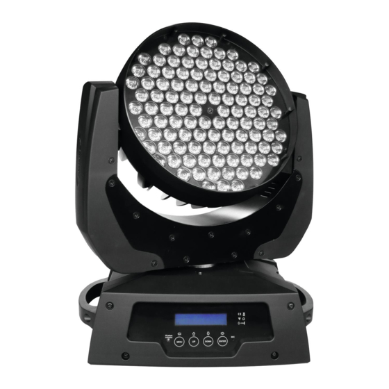
Geräteübersicht (1) Projektorkopf (2) LEDs (3) Projektorarm (4) Base (5) Tragegriff (6) Steuereinheit (7) Display (8) Statusanzeige W-DMX (9) Mode/Esc-Taste (10) Up-Taste (11) Down-Taste (12) Enter-Taste (13) Mikrofon (14) Lüfter (15) DMX-Ausgangsbuchse (16) DMX-Eingangsbuchse (17) Netzschalter (18) Sicherungshalter (19) Netzanschluss 8/48 00047714.DOC, Version 1.0... -
Page 9: Installation
INSTALLATION Projektormontage Die Aufhängevorrichtungen des Projektors muss so gebaut und bemessen sein, dass sie 1 Stunde lang ohne dauernde schädliche Deformierung das 10-fache der Nutzlast aushalten kann. Die Installation muss immer mit einer zweiten, unabhängigen Aufhängung, z. B. einem geeigneten Fangnetz, erfolgen. - Page 10 ACHTUNG! Montieren Sie den Projektor ausschließlich über einen geeigneten Haken. Bitte beachten Sie auch die Installationshinweise auf der Unterseite der Base. Achten Sie darauf, dass das Gerät sicher befestigt wird. Vergewissern Sie sich, dass die Verankerung stabil ist. Das Gerät kann direkt auf den Boden gestellt werden oder...
- Page 11 (1) Omega-Halter (2) Haken (3) Sicherheitsfangseil (4) Schnellverschluss Verschrauben Sie einen Haken über eine M10 Schraube und Mutter mit dem Omega-Halter. Führen Sie die beiden Schnellverschlüsse des Omega-Halters in die dafür vorgesehenen Öffnungen an der Geräteunterseite ein. Drehen Sie die Schnellverschlüsse im Uhrzeigersinn bis zum Anschlag fest.
-
Page 12: Anschluss An Den Dmx-512 Controller / Verbindung Projektor - Projektor
Anschluss an den DMX-512 Controller / Verbindung Projektor - Projektor Achten Sie darauf, dass die Adern der Datenleitung an keiner Stelle miteinander in Kontakt treten. Die Geräte werden ansonsten nicht bzw. nicht korrekt funktionieren. Beachten Sie, dass die Startadresse abhängig vom verwendeten Controller ist. Unbedingt Bedienungsanleitung des verwendeten Controllers beachten. -
Page 13: Anschluss Ans Netz
Anschluss ans Netz Schließen Sie das Gerät über die beiliegende Netzanschlussleitung ans Netz an. Die Belegung der Anschlussleitungen ist wie folgt: Leitung International Braun Außenleiter Blau Neutralleiter Gelb/Grün Schutzleiter Der Schutzleiter muss unbedingt angeschlossen werden! Wenn das Gerät direkt an das örtliche Stromnetz angeschlossen wird, muss eine Trennvorrichtung mit mindestens 3 mm Kontaktöffnung an jedem Pol in die festverlegte elektrische Installation eingebaut werden. -
Page 14: Dmx-Protokoll
Bitte beachten Sie: Schalten Sie das Gerät ein. Das Gerät prüft, ob DMX-512 Daten empfangen werden oder nicht. Werden keine Daten empfangen, blinkt das Display. Die Meldung erscheint -wenn kein XLR-Kabel (DMX Signalkabel vom Controller) in die DMX-Eingangsbuchse des Gerätes gesteckt wurde. - Page 15 Control-channel 8 - LED Strobe Decimal Hexad. Percentage Eigenschaft 0 31 00 1F 0% 12% S LEDs aus 32 63 20 3F 13% 25% S LEDs an 64 95 40 5F 25% 37% F Strobe-Effekt mit zunehmender Geschwindigkeit 96 127 60 7F 38% 50% S LEDs an...
-
Page 16: Control Board
Control Board Das Control Board bietet mehrere Möglichkeiten: so lassen sich z. B. die DMX-Startadresse eingeben, die Lampe ein- und ausschalten, das vorprogrammierte Programm abspielen oder ein Reset durchführen. Drücken Sie die Mode/Esc-Taste, so dass sich das Display einschaltet. Durch Drücken der Up/Down-Tasten können Sie sich im Hauptmenü... - Page 17 Rest WDMX Mem W-DMX ausloggen Zurücksetzen auf Reset default ON/OFF Werkseinstellungen Reset All Reset Alle Reset function Reset PAN/TILT Reset PAN/TILT Test channel PAN … Funktionstest der Kanäle Manuelle Einstellung der Manual control PAN ... PAN = XXX ... Kanäle PAN/TILT-Justierung;...
-
Page 18: Function Mode
Function Mode Einstellen der DMX-Startadresse Mit dieser Funktion können Sie die DMX-Startadresse über das Control Board einstellen. • Wählen Sie “Set DMX address” durch Drücken der Up/Down-Tasten. • Drücken Sie die Enter-Taste und stellen Sie die DMX-Adresse durch Drücken der Up/Down-Tasten ein. •... -
Page 19: Personality
Personality Status settings DMX-Adresse über externen Controller Mit dieser Funktion können Sie die DMX-Startadresse über einen externen Controller einstellen. • Wählen Sie “Address via DMX” durch Drücken der Up/Down-Tasten. • Drücken Sie die Enter-Taste, auf dem Display erscheint “ON” oder “OFF”. •... - Page 20 Umstellung von 16 auf 8 Bit Auflösung Mit dieser Funktion lässt sich das Gerät von 16 Bit auf 8 Bit Auflösung umstellen. • Wählen Sie “Fine resolution” durch Drücken der Up/Down-Tasten. • Drücken Sie die Enter-Taste, auf dem Display erscheint “ON” oder “OFF”. •...
-
Page 21: Drahtlos-Dmx (Optional Erhältlich)
Drahtlos-DMX (optional erhältlich) Für die drahtlose Datenübertragung benötigen Sie einen DMX-Controller, einen Drahtlos-Sender und einen Drahtlos-Empfänger bzw. Geräte mit eingebautem Drahtlos-Empfänger. Ist ein Gerät mit eingebautem Drahtlos-Empfänger über ein Kabel mit einem DMX-Controller verbunden, wird es vom kabelgebundenen Controller angesteuert und nicht vom Drahtlos-Sender. Der FUTURELIGHT EYE-108 bietet die Möglichkeit, durch ein optionales Drahtlos-Empfänger-Modul für W- DMX-Betrieb, ergänzt zu werden. -
Page 22: Reset Function
Bedeutung der Drahtlos Status-LEDs und ihrer Farben • Schnelles Blinken rot/grün: Einlog-Modus, der Drahtlos-Empfänger loggt sich am Drahtlos-Sender ein. • Langsames Blinken rot/grün: Funkverbindung mit einem Sender. Der Sender empfängt kein DMX-Signal vom Controller. • Grün leuchtet permanent: Der Drahtlos-Empfänger ist am Drahtlos-Sender eingeloggt. Das DMX-Signal liegt an und wird empfangen. - Page 23 Exkurs: Ein Mastergerät kann 3 verschiedene Datengruppen zu den Slavegeräten senden. Das bedeutet, dass ein Mastergerät 3 verschiedene Slaveeinheiten starten kann, in welchen 3 unterschiedliche Programme ablaufen. Die Mastereinheit sendet die 3 Programmteile in Schleife. Das Slavegerät empfängt die Daten vom Mastergerät nach der Gruppe, in die das Slavegerät eingeordnet wurde.
-
Page 24: Reinigung Und Wartung
5. Automatische Szenenaufzeichnung • Wählen Sie “Edit program” durch Drücken der Up/Down-Tasten. • Drücken Sie die Enter-Taste zur Bestätigung. • Wählen Sie “Edit scenes” durch Drücken der Up/Down-Tasten. • Drücken Sie die Enter-Taste zur Bestätigung. • Drücken Sie die Up/Down-Taste, um die gewünschten Szenennummern einzustellen. Es können maximal 250 Szenen programmiert werden. -
Page 25: Sicherungswechsel
LEBENSGEFAHR! Vor Wartungsarbeiten unbedingt allpolig vom Netz trennen! Das Gerät sollte regelmäßig von Verunreinigungen wie Staub usw. gereinigt werden. Verwenden Sie zur Reinigung ein fusselfreies, angefeuchtetes Tuch. Auf keinen Fall Alkohol oder irgendwelche Lösungsmittel zur Reinigung verwenden! Den Lüfter monatlich reinigen. Reinigen Sie das Innere des Projektors mindestens einmal im Jahr mit einem Staubsauger oder einer Luftbürste. -
Page 26: Technische Daten
TECHNISCHE DATEN Spannungsversorgung: 100-240 V AC, 50/60 Hz ~ Gesamtanschlusswert: 340 W DMX-Steuerkanäle: DMX 512-Anschluss: 3-pol. XLR Blitzrate: 25 Hz Max. Schwenkbewegung (Pan) 630°: in 2,5 s Max. Kippbewegung (Tilt) 265°: in 1,5 s Anzahl der LEDs: Abstrahlwinkel: ca. 40° Maße (LxBxH): 325 x 230 x 445 mm Gewicht:... -
Page 27: Introduction
USER MANUAL EYE-108 RGBW LED-Head-Effect CAUTION! Keep this device away from rain and moisture! Unplug mains lead before opening the housing! For your own safety, please read this user manual carefully before you initially start-up. Every person involved with the installation, operation and maintenance of this device has to... -
Page 28: Safety Instructions
SAFETY INSTRUCTIONS CAUTION! Be careful with your operations. With a dangerous voltage you can suffer a dangerous electric shock when touching the wires! This device has left our premises in absolutely perfect condition. In order to maintain this condition and to ensure a safe operation, it is absolutely necessary for the user to follow the safety instructions and warning notes written in this user manual. -
Page 29: Operating Determinations
running, the device must be checked by a specialist if the liquid has reduced any insulation. Reduced insulation can cause mortal electrical shock. There must never be any objects entering into the device. This is especially valid for metal parts. If any metal parts like staples or coarse metal chips enter into the device, the device must be taken out of operation and disconnected immediately. -
Page 30: Description Of The Device
Make sure that the area below the installation place is blocked when rigging, derigging or servicing the fixture. For overhead use (mounting height >100 cm), always fix the fixture with an appropriate safety-rope. Fix the safety-rope at the correct fixation points only. The safety-rope must never be fixed at the transport handles! Only operate the fixture after having checked that the housing is firmly closed and all screws are tightly fastened. -
Page 31: Overview
Overview (1) Projector head (2) LEDs (3) Yoke (4) Base (5) Carrying handle (6) Control Board (7) Display (8) W-DMX indicator (9) Mode/Esc-button (10) Up-button (11) Down-button (12) Enter-button (13) Microphone (14) Fan (15) DMX-Out socket (16) DMX-In socket (17) Power switch (18) Fuseholder (19) Power supply 31/48... -
Page 32: Installation
INSTALLATION Rigging The installation of the projector has to be built and constructed in a way that it can hold 10 times the weight for 1 hour without any harming deformation. The installation must always be secured with a secondary safety attachment, e.g. an appropriate catch net. This secondary safety attachment must be constructed in a way that no part of the installation can fall down if the main attachment fails. - Page 33 The Moving-Head can be placed directly on the stage floor rigged orientation truss without altering its operation characteristics (see drawing). The fixture’s base enables to be mounted in two ways. For overhead use (mounting height >100 cm), always install an appropriate safety bond.
- Page 34 (1) Omega-holder (2) Clamp (3) Safety-rope (4) Quick-lock fastener Screw the clamp via a M10 screw and nut onto the Omega-holder. Insert the quick-lock fasteners of the Omega-holder into the respective holes on the bottom of the device. Tighten the quick-lock fasteners fully clockwise. 34/48 00047714.DOC, Version 1.0...
-
Page 35: Dmx-512 Connection / Connection Between Fixtures
DMX-512 connection / connection between fixtures The wires must not come into contact with each other, otherwise the fixtures will not work at all, or will not work properly. Please note, the starting address depends upon which controller is being used. Only use a stereo shielded cable and 3-pin XLR-plugs and connectors in order to connect the controller with the fixture or one fixture with another. -
Page 36: Connection With The Mains
Connection with the mains Connect the device to the mains with the enclosed power supply cable. The occupation of the connection-cables is as follows: Cable International Brown Live Blue Neutral Yellow/Green Earth The earth has to be connected! If the device will be directly connected with the local power supply network, a disconnection switch with a minimum opening of 3 mm at every pole has to be included in the permanent electrical installation. -
Page 37: Dmx-Protocol
This situation can occur if: - the XLR plug (cable with DMX signal from controller) is not connected with the input of the device. - the controller is switched off or defective, if the cable or connector is defective or the signal wires are swap in the input connector. - Page 38 Steuerkanal 8 - LED Strobe Decimal Hexad. Percentage S/F Feature 0 31 00 1F 0% 12% S LEDs off 32 63 20 3F 13% 25% S LEDs on 64 95 40 5F 25% 37% F Strobe-effect with increasing speed 96 127 60 7F 38% 50% S LEDs on...
-
Page 39: Control Board
Control Board The Control Board offers several features: you can simply set the starting address, switch on and off the lamp, run the pre-programmed program or make a reset. The main menu is accessed by pressing Mode/Esc until the display is lit. Browse through the menu by pressing Up or Down. - Page 40 Rest WDMX Mem Logout W-DMX Reset default ON/OFF Restore factory sett. Reset all motors Reset All Reset function Reset PAN/TILT Reset only PAN/TILT Test channel PAN … Test function Manual control PAN ... PAN = XXX ... Manual adjustment PAN/TILT adjustment --Password-- Password = XXX Calibrate Values...
-
Page 41: Function Mode
Function Mode DMX address setting With this function, you can adjust the desired DMX-address via the Control Board. • Select “Set DMX address“ by pressing Up or Down. • Press the Enter-button, adjust the DMX address by pressing Up or Down. •... -
Page 42: Personality
Personality Status settings Address via DMX With this function, you can adjust the desired DMX-address via an external controller. • Select “Address via DMX“ by pressing Up or Down. • Press the Enter-button, the display shows “ON” or “OFF”. • Press Up or Down to select “ON” if you wish to enable this function or “OFF” if you don’t. •... -
Page 43: Wireless Dmx (Optional Available)
Automatic PAN/TILT calibration With this function you can calibrate the PAN/TILT movement to the correct starting position. Adjust PAN/TILT speed With this function you can define the PAN/TILT speed. You can select one of 4 different modes. Mic sensitivity With this function, you can select the desired microphone sensitivity between 0 % and 99 %. •... -
Page 44: Installation Of A Wireless Dmx-System
Please note: When the W-DMX system is activated, the link between the built-in DMX input (XLR mounting plug) is electronically turned off, but the DMX output (XLR mounting socket) will function normally. If a device is powered on when the built-in W-DMX system is activated, the fixture will automatically scan for a wireless DMX signal from a W-DMX transmitter. -
Page 45: Users Mode Set
Calibrate Values With this function, you can calibrate the PAN/TILT angle. The password for this function is „050“. Users mode set User mode With this function, you can create user defined channel orders. Edit User mode With this function, you can adjust the Preset user defined channel order. Edit program Select program for auto program With this function, you can select the program for the Program Run. - Page 46 3. Program selection for Auto Pro Part • Select “Edit program” by pressing Up or Down. • Press the Enter-button to confirm. • Select “Select programs” by pressing Up or Down. • Press the Enter-button to confirm. • Press Up or Down to select “Auto Pro Part 1”, “Auto Pro Part 2” or “Auto Pro Part 3”, and thus select which Slave program is to be sent.
-
Page 47: Cleaning And Maintenance
CLEANING AND MAINTENANCE The operator has to make sure that safety-relating and machine-technical installations are inspected by an expert after every four years in the course of an acceptance test. The operator has to make sure that safety-relating and machine-technical installations are inspected by a skilled person once a year. -
Page 48: Technical Specifications
TECHNICAL SPECIFICATIONS Power supply: 100-240 V AC, 50/60 Hz ~ Power consumption: 340 W DMX-control-channels: DMX-512-connection: 3-pin XLR Flash-rate: 25 Hz Maximum PAN-movement 630°: in 2.5 s Maximum TILT-movement 265°: in 1.5 s Number of LEDs: Beam angle: approx. 40° Dimensions (LxWxH): 325 x 230 x 445 mm Weight:...
Need help?
Do you have a question about the EYE-108 RGBW and is the answer not in the manual?
Questions and answers