Toro TITAN ZX 5400 Operator's Manual
Zero-turn-radius riding mower
Hide thumbs
Also See for TITAN ZX 5400:
- Operator's manual (60 pages) ,
- Setup instructions (4 pages) ,
- Operator's manual (60 pages)
Table of Contents

Subscribe to Our Youtube Channel
Related Manuals for Toro TITAN ZX 5400


Summary of Contents for Toro TITAN ZX 5400
- Page 1 Form No. 3394-232 Rev A TITAN ® ZX 4800 and ZX 5400 Zero-Turn-Radius Riding Mower Model No. 74846—Serial No. 315000001 and Up Model No. 74848—Serial No. 315000001 and Up g024406 *3394-232* A Register at www.Toro.com. Original Instructions (EN)
- Page 2 This manual uses 2 other words to highlight information. Important calls attention to special mechanical information You may contact Toro directly at www.Toro.com for product and Note emphasizes general information worthy of special safety and operation training materials, accessory information, attention.
-
Page 3: Table Of Contents
Checking the Hydraulic Oil Level......40 Rotary Lawnmower Machines ....... 4 Changing the Hydraulic System Filter and Safe Operating Practices........... 4 Oil ..............40 Toro Riding Mower Safety ........5 Mower Deck Maintenance...........42 Model 74846............6 Servicing the Cutting Blades........42 Model 74848............6 Mower Deck Leveling ..........45... -
Page 4: Safety
Preparation Safety • While mowing, always wear substantial, slip-resistant footwear and long trousers. Do not operate the This machine has been designed in accordance with EN ISO equipment when barefoot or wearing open sandals. 5395:2013. • Thoroughly inspect the area where the equipment is to be used and remove all objects which may be thrown by Safe Operation Practices the machine. -
Page 5: Toro Riding Mower Safety
Do not change the engine governor settings or overspeed the engine. Operating the engine at excessive speed can The following list contains safety information specific to Toro increase the hazard of personal injury. products or other safety information that you must know that •... -
Page 6: Model 74846
• Follow the manufacturer's recommendations for wheel Uncertainty Value (K) = 0.19 m/s2 weights or counterweights to improve stability. Measured values were determined according to the procedures • Use extreme care with grass catchers or other attachments. outlined in EN ISO 5395:2013 (Riding & Stand-Ons). These can change the stability of the machine and cause loss of control. -
Page 7: Slope Indicator
Slope Indicator G011841 Figure 3 This page may be copied for personal use. 1. The maximum slope you can safely operate the machine on is 15 degrees. Use the slope chart to determine the degree of slope of hills before operating. Do not operate this machine on a slope greater than 15 degrees. Fold along the appropriate line to match the recommended slope. -
Page 8: Safety And Instructional Decals
Safety and Instructional Decals Safety decals and instructions are easily visible to the operator and are located near any area of potential danger. Replace any decal that is damaged or lost. 114-1606 1. Entanglement hazard, belt—keep all guards in place. 99-8936 1. - Page 9 117-1194 1. Engine 130-0655 1. Fuel tank 3. Half 2. Full 4. Empty 130-0731 1. Warning—thrown object 2. Cutting hazard of hand or hazard; keep the deflector foot, mower blade—keep shield in place. away from moving parts. 130-0654 1. Transport—lock 3.
- Page 10 130-0765 1. Read the Operator's 3. Remove the key from Manual. the ignition and read the Operator's Manual before permorning maintenance. 2. Height-of-cut selection 130-6927 1. Warning—always use the ROPS and wear the seat belt when seated in the operator's position. 130-6928 1.
- Page 11 131-4036 1. The maximum drawbar 2. Read the Operator's pull is 36 kg (80 lb). Manual. 130-6996 1. Read the Operator's 4. Check the hydraulic oil Manual for information on every 25 hours maintenance. 2. Check the engine oil every 5.
-
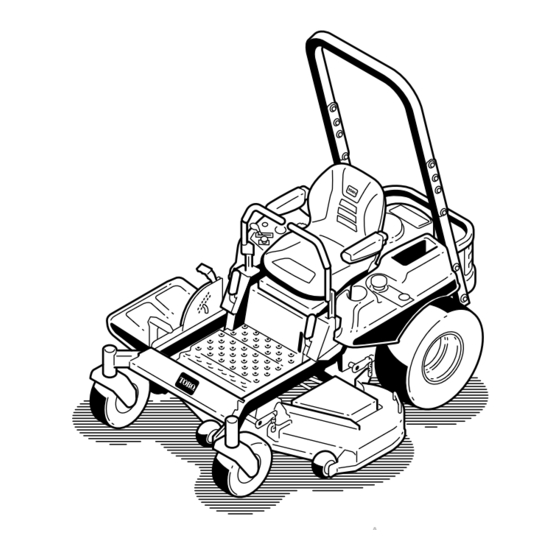
Page 12: Product Overview
Product Overview g024328 Figure 4 1. Drive wheel 4. Motion control levers 7. Front caster wheel 10. Deflector 2. Operator seat 5. Parking brake 8. Anti-scalp roller 3. Roll over protection system 6. Footrest 9. Foot pedal deck lift and (ROPS) height-of-cut... -
Page 13: Controls
It operates when the blade control switch (PTO) is its capabilities. Contact your Authorized Service Dealer or engaged. Use these times for scheduling regular maintenance Distributor or go to www.Toro.com for a list of all approved (Figure attachments and accessories. -
Page 14: Operation
Operation WARNING Gasoline is harmful or fatal if swallowed. Long-term Note: Determine the left and right sides of the machine exposure to vapors can cause serious injury and from the normal operating position. illness. • Avoid prolonged breathing of vapors. Adding Fuel •... -
Page 15: Think Safety First
Fuel Gauge 3. Install the fuel tank cap securely and tighten until it “clicks”. Wipe up any gasoline that may have spilled. Use the fuel window below the operator to verify the level of gasoline before filling the tank (Figure Think Safety First Please carefully read all of the safety instructions and decals in the safety section. -
Page 16: Using The Rollover Protection System (Rops)
Understanding the Safety Interlock CAUTION System This machine produces sound levels in excess of 85 dBA at the operators ear and can cause hearing loss The safety interlock system is designed to prevent the engine through extended periods of exposure. from starting unless: •... -
Page 17: Operating The Parking Brake
Operating the Parking Brake 1. If the engine is cold, use the choke to start the engine. 2. Pull up on the choke knob to engage the choke before Always set the parking brake when you stop the machine or using the ignition switch (Figure 14). -
Page 18: Starting And Stopping The Engine
Starting and Stopping the Stopping the Engine Engine CAUTION Injury can occur if children or bystanders move Starting the Engine or attempt to operate the machine while it is unattended. Note: A warm or hot engine may not require choking (Figure 16). -
Page 19: Operating The Mower Blade Control Switch (Pto)
Operating the Mower Blade Using the Motion Control Levers Control Switch (PTO) The blade control switch (PTO) starts and stops the mower blades and any powered attachments. Engaging the Blade Control Switch (PTO) Engage the blade control switch (PTO) with the throttle position at Fast. -
Page 20: Stopping The Machine
Stopping the Machine WARNING Children or bystanders may be injured if they move or attempt to operate the machine while it is unattended. Always remove the ignition key and move the motion control levers outward to the park position when leaving the machine unattended, even if just for a few minutes. - Page 21 Using the Foot Pedal Deck Lift System • Press the pedal down to raise the deck; continue to press the pedal until the deck is locked in the transport position (Figure 23). • Push on the deck lift pedal with your foot and pull the transport lock handle rearward to disengage the transport lock (Figure...
-
Page 22: Adjusting The Anti-Scalp Rollers
Adjusting the Anti-Scalp Rollers Whenever you change the height-of-cut, it is recommended to adjust the height of the anti-scalp rollers. 1. Disengage the blade control switch (PTO), move the motion control levers to the neutral lock position and set the parking brake. 2. -
Page 23: Pushing The Machine By Hand
Pushing the Machine by Hand DANGER Open holes in the mower expose you and others to Important: Always push the machine by hand. Never thrown debris. Debris thrown out of holes in the tow the machine because damage may occur. mower can cause injury. -
Page 24: Converting The 54 Inch Mower To Side Discharge
G012800 Figure 32 G012806 1. Carriage bolt, existing 3. Cut off baffle, shipped Figure 30 loose 2. Rear holes in the 4. Locknut, existing 1. Baffle guard 3. Carriage bolt (5/16 x 3/4 discharge plate inch) 2. Locknut (5/16 inch) 4. - Page 25 G010712 3. Remove the mower as described in the Removing the Mower procedure in the Maintenance section for more information. 4. Turn the mower upside down. 5. Remove the existing mower blades installed on your deck. Refer to the Removing the Blades procedure in the Maintenance section for more information.
-
Page 26: Using The Side Discharge
17. Install the mower as described in the Installing the Mower procedure in the Maintenance section for more information. Using the Side Discharge The mower has a hinged grass deflector that disperses clippings to the side and down toward the turf. DANGER Without a grass deflector, discharge cover, or complete grass catcher assembly mounted in... -
Page 27: Transporting The Machine
Transporting the Machine Loading the Machine Use a heavy-duty trailer or truck to transport the machine. Use extreme caution when loading or unloading machines Ensure that the trailer or truck has all necessary brakes, onto a trailer or a truck. Use a full-width ramp that is wider lighting, and marking as required by law. - Page 28 WARNING Loading a machine onto a trailer or truck increases the possibility of tip-over and could cause serious injury or death. • Use extreme caution when operating a machine on a ramp. • Ensure that the ROPS is in the up position and use the seat belt when loading or unloading the machine.
-
Page 29: Operating Tips
File down any nicks and sharpen the blades as necessary. If a blade is damaged or worn, replace it Mowing Direction immediately with a genuine TORO replacement blade. Alternate mowing direction to keep the grass standing straight. This also helps disperse clippings which enhances decomposition and fertilization. -
Page 30: Maintenance
Maintenance Recommended Maintenance Schedule(s) Maintenance Service Maintenance Procedure Interval • Change the engine oil. After the first 8 hours • Change the hydraulic system filter and oil. After the first 50 hours • Check the safety interlock system. • Check the engine oil level. •... - Page 31 Figure 40 Located on the seat pan underside 1. Read the Operator's Manual before performing any 4. Check the hydraulic oil every 25 hours maintenance. 2. Check the engine oil every 8 hours 5. Check the caster wheel tire pressure every 25 hours 3.
-
Page 32: Premaintenance Procedures
Premaintenance Lubrication Procedures Greasing the Bearings Raising the Seat Service Interval: Every 25 hours—Grease all lubrication points. Make sure the motion control levers are locked in the neutral Grease Type: No. 2 general purpose lithium base grease lock position. Lift the seat forward. 1. -
Page 33: Engine Maintenance
Engine Maintenance Cleaning the Element Service Interval: Every 100 hours—Service the paper element (more often in dusty, dirty WARNING conditions). Contact with hot surfaces may cause personal Every 200 hours/Yearly (whichever comes injury. first)—Replace the paper element (more often in dusty, dirty conditions). -
Page 34: Changing The Engine Oil
Changing the Engine Oil engine with oil below the low mark because the engine may be damaged. Service Interval: After the first 8 hours—Change the engine 1. Park the machine on a level surface, disengage the oil. blade control switch, stop the engine, engage parking Every 100 hours—Change the engine oil (more often brake, and remove the key. -
Page 35: Servicing The Spark Plug
g027660 Figure 47 Changing the Engine Oil Filter g027477 Figure 48 Service Interval: Every 200 hours—Change the oil filter. (more often in dusty, dirty conditions) Note: Ensure the oil filter gasket touches the engine Note: Change the engine oil filter more frequently when and then an extra 3/4 turn is completed. -
Page 36: Cleaning The Cooling System
g027478 Figure 49 16 ft-lb 22 N-m Note: Due to the deep recess around the spark plug, blowing out the cavity with compressed air is usually the most effective method for cleaning. The spark plug is most accessible when the blower housing is removed for cleaning. -
Page 37: Fuel System Maintenance
Fuel System Electrical System Maintenance Maintenance Replacing the Fuel Filter Servicing the Battery Service Interval: Every 100 hours/Yearly (whichever comes Service Interval: Monthly first) (more often under dusty, dirty conditions). DANGER 1. Disengage the blade control switch (PTO), move the Battery electrolyte contains sulfuric acid which is a motion control levers to the neutral lock position, and deadly poison and causes severe burns. -
Page 38: Servicing The Fuses
Important: Always keep the battery fully charged. This is especially important to prevent battery damage when the temperature is below 32°F (0°C). 1. Charge battery for 10 to 15 minutes at 25 to 30 amps or 30 minutes at 10 amps. 2. -
Page 39: Drive System Maintenance
Drive System Maintenance Checking the Tire Pressure Service Interval: Every 25 hours—Check tire pressure. Maintain the air pressure in the front and rear tires as specified. Uneven tire pressure can cause uneven cut. Check the pressure at the valve stem (Figure 57). -
Page 40: Hydraulic System Maintenance
4.495 liters (152 oz) or larger. Hydraulic System Oil Specification 1. Stop engine, wait for all moving parts to stop, and Oil Type: Toro HYPR-OIL® 500 or 20w-50 motor oil. allow engine to cool. Remove the key and engage the parking brake. -
Page 41: Bleeding The Hydraulic System
Bleeding the Hydraulic System 1. Raise the rear of machine up and support with jack stands (or equivalent support) just high enough to allow drive wheels to turn freely. G010333 Figure 61 1. Jacking points 2. Enter the operator's position. Start engine and move throttle control ahead to 1/2 throttle position. -
Page 42: Mower Deck Maintenance
File down any nicks and sharpen the blades as necessary. If a blade is damaged or worn, replace it immediately with a genuine Toro replacement blade. For Checking for Bent Blades convenient sharpening and replacement, you may want to keep extra blades on hand. -
Page 43: Removing The Blades
3 mm (1/8 inch), the blade spindle could be bent. Contact an Authorized Toro Dealer for service. 5. Measure from the tip of the blade to the flat surface here. The variance should be no more than 3 mm (1/8 B. - Page 44 Figure 69 1. Blade 2. Balancer Installing the Blades 1. Install the blade onto the spindle shaft (Figure 67). Important: The curved part of the blade must be pointing upward toward the inside of the mower to ensure proper cutting. 2.
-
Page 45: Mower Deck Leveling
Mower Deck Leveling (5/16 inch) lower than the rear of the mower, adjust the blade level using the following instructions: Check to ensure the mower deck is level any time you install 1. Park the machine on a level surface and disengage the the mower or when you see an uneven cut on your lawn. -
Page 46: Inspecting The Belts
6. Remove the floor pan to access the idler pulley; refer to the Removing the Floor Pan procedure in Premaintenance. 7. Using a spring removal tool, (Toro part no. 92-5771), remove the idler spring from the deck post to remove tension on the idler pulley (Figure 74). -
Page 47: Removing The Mower
The spring is under tension when installed and can cause personal injury. Be careful when removing the belt. 11. Using a spring removal tool, (Toro part no. 92-5771), install the idler spring over the deck post and placing tension on the idler pulley and mower belt (Figure 74). -
Page 48: Installing The Mower Deck
Removing the Mower Deck Installing the Mower Deck 1. Remove the hair pin cotter and washer securing the 1. Park the machine on a level surface and disengage the long, link pin to the frame and deck; remove the link blade control switch. - Page 49 g028042 G024316 Figure 77 Figure 78 1. Deflector 4. Spring 1. Rod and spring assembly 3. Rod, short end, moved 2. Deck brackets 5. Spring installed over the partially installed behind mower bracket 2. Loop end of the spring 4. Short end, retained by 3.
-
Page 50: Cleaning
Cleaning 5. Sit on the seat and start the engine. Engage the blade control switch and let the mower run for one to three minutes. Washing the Underside of the 6. Disengage the blade control switch, stop the engine, Mower and remove the ignition key. -
Page 51: Storage
Storage C. Stop the engine, allow it to cool, and drain the fuel tank. D. Restart the engine and run it until it stops. Cleaning and Storage E. Dispose of fuel properly. Recycle the fuel 1. Disengage the blade control switch (PTO), set the according to local codes. -
Page 52: Troubleshooting
Troubleshooting Problem Possible Cause Corrective Action Starter does not crank 1. Blade control switch (PTO) is engaged. 1. Move blade control switch (PTO) to disengaged. 2. Parking brake is not on. 2. Set the parking brake. 3. Drive levers are not in neutral lock 3. - Page 53 Problem Possible Cause Corrective Action Machine does not drive. 1. By pass valves is not closed tight. 1. Tighten the by pass valves. 2. Pump belt is worn, loose or broken. 2. Change the belt. 3. Pump belt is off a pulley. 3.
-
Page 54: Schematics
Schematics Wire Diagram (Rev. B) - Page 55 The Way Toro Uses Information Toro may use your personal information to process warranty claims, to contact you in the event of a product recall and for any other purpose which we tell you about. Toro may share your information with Toro's affiliates, dealers or other business partners in connection with any of these activities. We will not sell your personal information to any other company.
- Page 56 Authorized Toro Service Dealer. tractor structure that other components such as the engine are secured to, cracks or breaks in normal use, it will be repaired or replaced, at Toro's option, under warranty at no cost for parts and General Conditions labor.
Need help?
Do you have a question about the TITAN ZX 5400 and is the answer not in the manual?
Questions and answers