Table of Contents
Advertisement
Quick Links
Form No. 3360-955 Rev A
TITAN
®
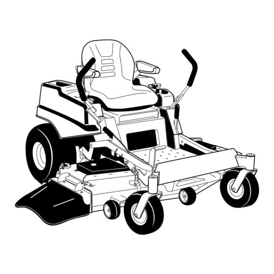
ZX5400 and ZX6000
Zero-Turn-Radius Riding Mower
Model No. 74822—Serial No. 290000001 and Up
Model No. 74823—Serial No. 290000001 and Up
G009968
To register your product or download an Operator's Manual or Parts Catalog at no charge, go to www.Toro.com.
Original Instructions (EN)
Advertisement
Table of Contents


Need help?
Do you have a question about the 74822 and is the answer not in the manual?
Questions and answers