AGA Six Four Series Owner's Manual
Conventional range cooker with ceramic hob
Hide thumbs
Also See for Six Four Series:
- Assembly instructions manual (9 pages) ,
- Assembly instructions manual (9 pages)
Table of Contents
Advertisement
Quick Links
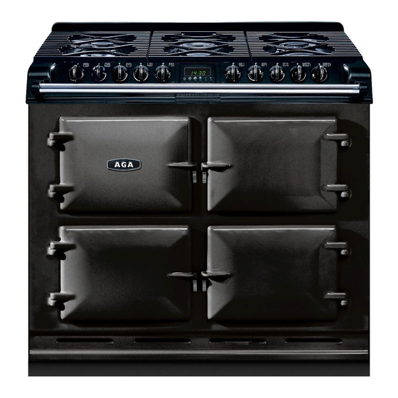
AGA SIX-FOUR SERIES - CERAMIC HOB
OWNERS MANUAL
DESN 513131
Comprising
Servicing, Installation &
Users Guide
Remember, when replacing a part on this appliance, use only spare parts that you can be assured conform to the safety
and performance specification that we require. Do not use reconditioned or copy parts that have not been clearly authorised
by AGA.
PLEASE READ THESE INSTRUCTIONS BEFORE USING THIS APPLIANCE
For use in GB and IE
12/15 EINS 517080
Advertisement
Table of Contents

Related Manuals for AGA Six Four Series


Summary of Contents for AGA Six Four Series
- Page 1 AGA SIX-FOUR SERIES - CERAMIC HOB OWNERS MANUAL DESN 513131 Comprising Servicing, Installation & Users Guide Remember, when replacing a part on this appliance, use only spare parts that you can be assured conform to the safety and performance specification that we require. Do not use reconditioned or copy parts that have not been clearly authorised by AGA.
-
Page 2: Table Of Contents
CONTENTS SECTION PAGE INTRODUCTION APPLIANCE VIEW INSTALLATION SECTION TECHNICAL DATA INSTALLATION FITTING AND PRODUCT DIMENSIONS ELECTRICAL CONNECTION 8 - 9 LEVELLING AND MOBILITY WHEELS SPLASHBACK USERS GUIDE WARNINGS CONTROL PANEL SETTING UP THE COOKER FOR USE CERAMIC HOB THE GRILL THE OVENS (GENERAL) FITTING AND REMOVAL OF OVEN SHELVES SIMMERING OVEN... -
Page 3: Introduction
IMPORTANT NOTICE: PLEASE READ THE ACCOMPANYING WARRANTY. Any alteration that is not approved by AGA could invalidate the approval of the appliance, operation of the warranty and could affect your statutory rights. -
Page 4: Appliance View
APPLIANCE VIEW HOTPLATE DUAL ELEMENT REAR TRIM SINGLE ELEMENT TIMER SURROUND SPLASHBACK SINGLE HISPEED DUAL ELEMENT ELEMENT HOTPLATE SIDE TRIMS CONTROLS GRILL HANDRAIL COMPARTMENT UPPER FAN OVEN LOWER FAN OVEN TIMER DATA PLAQUE SIMMERING OVEN Fig. 1 DESN 517095... -
Page 5: Installation Section
Remember, when replacing a part on this appliance, use only spare parts that you can be assured conform to the safety and performance specification that we require. Do not use reconditioned or copy parts that have not been clearly authorised by AGA. -
Page 6: Technical Data
This appliance is designed for the voltage stated on the data plate, which is situated in the right hand vent slot at the base of the appliance. The AGA Six-Four Series Ceramic Hob is supplied from the manufacturers as a fully tested chassis construction. Ceramic hob, doors, splashback and handrail are assembled during installation. -
Page 7: Fitting And Product Dimensions
FITTING AND PRODUCT DIMENSIONS Any adjacent walls that project above the height of the hob must be of heat resistant material. Any side wall above the cooker on either side shall not be less than 60mm horizontally from the cooker. (See Fig. 2). A minimum clearance of 1000mm must be available at the front of the cooker to enable it to be serviced. -
Page 8: Electrical Connection
ELECTRICAL CONNECTION ELECTRICAL CONNECTION IS LOCATED AT THE TOP RIGHT HAND SIDE OF THE APPLIANCE, BEHIND SIDE PANEL. DURING INSTALLATION REMOVE THE RIGHT HAND SIDE PANEL TO CONNECT ELECTRICAL SUPPLY. Remove 3 screws securing side panel to gain access to mains terminal. See Fig. 4 for location of cover. Remember that the mains electrical cable must be routed through the grommet at the rear right hand side of the cooker near the top, before connecting to the mains terminal connection. - Page 9 ELECTRICAL CONNECTION (CONTINUED) THREE PHASE CONNECTION - Minimum 2.5mm cable and must comply with the latest editions of the local and national wiring regulations. L1 - 5.25 kW L2 - 4.50 kW Fig. 3A DESN 517107 L3 - 5.45 kW CABLE ENTRY SIDE PANEL...
-
Page 10: Levelling And Mobility Wheels
Installation/Levelling The AGA Six-Four Series Ceramic Hob is designed to stand on a flat and level surface, any unevenness may be overcome by adjusting the four levelling feet, one at each corner of the base plate. The adjusting screws are accessed by removing the hotplate casting (See section ‘To Remove Ceramic Hob and Frame’... -
Page 11: Splashback
SPLASHBACK 1. Locate tabs on rear of splashback assembly, into the brackets on the upper rear of the cooker. (See Fig. 6). Push fully into place. Fig. 6 DESN 513137... -
Page 12: Users Guide
Users Guide... -
Page 13: Warnings
WARNINGS WARNING: The appliance and its accessible parts become hot during use. Care should be taken to avoid touching heating elements. Children less than 8 years of age shall be kept away unless continuously supervised. • The appliance can be used by children aged from 8 years and above and persons with reduced physical, sensory or mental capabilities or lack of experience and knowledge if they have been given supervision or instruction concerning use of the appliance in a safe way and understand the hazards involved. -
Page 14: Control Panel
CONTROL PANEL Fig. 7 DESN 517098 The GRILL ELEMENT CONTROL KNOB needs to be pushed in before turning in either direction. Clockwise both elements on Anti-clockwise middle element only The HOB CONTROL KNOBS controls are operated also by pushing in the knob before turning to the required setting. The OVEN KNOBS which do not need to be pushed in, can only be rotated clockwise from the OFF position. -
Page 15: Setting Up The Cooker For Use
SETTING UP THE COOKER FOR USE • Press and hold the button. Now press the [+] or [-] buttons to increase or decrease the time (Fig. 9). Holding the [+] or [-] buttons for more than 2 seconds will advance/decrease the set time quickly. Release the buttons to set the time of day. -
Page 16: Ceramic Hob
CERAMIC HOB DO NOT USE THE HOB IF IT IS CRACKED. DO NOT PLACE ALUMINIUM FOIL ON THE HOB SURFACE. The hob has the six following plates:- front left - double circuit - 2.0 kW/0.70 kW - 205/120mm dia - rapid heat up rear left - single circuit - 1.1 kW - 140mm dia - rapid heat up front centre - single circuit - 1.1 kW - 140mm dia - rapid heat up rear centre - double circuit - 2.0 kW/0.70 kW - 205/120mm dia - rapid heat up... -
Page 17: The Grill
THE GRILL THE GRILL COMPARTMENT DOOR MUST BE KEPT OPEN WHEN THE GRILL IS ON. Caution: Accessible parts may be hot when the grill is on. Young children should be kept away. The very high speed instant grill is divided into two areas to save energy and to suit individual grilling requirements. Turn the grill control clockwise and the whole of the grilling area can be used for large amounts of food. -
Page 18: The Ovens (General)
THE OVENS (GENERAL) General The shelves are designed to be non-tilt. Shelf positions are counted from the bottom. Put dishes in the centre of the shelf. To remove a shelf, lift clear of the side notches and slide forward. To replace a shelf, insert into the oven with the short prongs at the rear, facing upwards. -
Page 19: Fitting And Removal Of Oven Shelves
FITTING AND REMOVAL OF OVEN SHELVES Oven Shelves - These shelves are designed to slide out STOP ON SHELF MUST PROJECT UPWARDS SHELF STOP AND ANTI TILT BRACKET DESN 511867 Refit as follows: Locate in guide as above. DESN 511866 Please Note: Shelf slides out to stop position. -
Page 20: Simmering Oven
USING THE SIMMERING OVEN SETTING Points to bear in mind when preparing food. For best results use the AGA Stainless Steel cookware. Do not place dishes directly on to the oven base. Always place onto shelf supplied (See Fig. 11B). -
Page 21: Fan Oven - Cooking Hints
Fan Oven • Fan Oven • Fan Oven • Fan Oven • Fan Oven • Fan Oven • Fan Oven • Fan Oven • Fan Oven • Cooking Hints The left hand lower oven and right hand upper oven are fan ovens, which means that the air is circulated to create an even temperature throughout. - Page 22 Fan Oven • Fan Oven • Fan Oven • Fan Oven • Fan Oven • Fan Oven • Fan Oven • Fan Oven • Fan Oven • Fan Oven • SETTING FOOD APPROXIMATE COOKING TIME °C Yeast Mixtures Bread - loaves 200 - 210 30 - 45 mins Bread - rolls...
-
Page 23: Using The Automatic Cooking Facility
USING THE AUTOMATIC COOKING FACILITY AUTOMATIC COOKING CONTROL This can be used to set an automatic cooking programme. It switches the oven on and off at the pre-set times. It controls the lower left hand fan oven only. The maximum length of cooking programme which can be set is 23 hours and 59 minutes e.g. - Page 24 USING THE AUTOMATIC COOKING FACILITY Fig. 16 DESN 517074 Fig. 19 DESN 517077 Now press and hold the button (Fig. 17) and then Set the oven to the required temperature. When cooking press the [+] button (or [-] button) until the required 'stop is finished [AUTO] will flash and the beeper will sound.
-
Page 25: Using The Automatic Cooking Facility
USING THE AUTOMATIC COOKING FACILITY For an overview of the functions refer to table below. Symbol Function Notes Used with the [+] and [-] Sets the Minute Minder buttons Sets the duration/ Used with the [+] and [-] cook period buttons Sets the end/ Used with the [+] and [-]... -
Page 26: Cleaning And Caring For Your Cooker
CLEANING & CARING FOR YOUR COOKER General Always switch OFF at the mains before cleaning. When cleaning use as little water as possible. Do not use a steam cleaner to clean this cooker. If milk or fruit juice or anything containing acid or sugar is spilled on the cooker or hob, wipe it up immediately. Clean off any condensation streaks on the front plate around the oven doors or the vitreous enamel may be permanently discoloured. - Page 27 CLEANING & CARING FOR YOUR COOKER COOKER PART AND FINISH CLEANING METHOD Clean with a damp cloth and hot soapy water. Stubborn Vitreous Enamel stains can be removed with mild cream, paste or liquid Fan ovens and simmering oven all sides cleaners, or by gently rubbing with a well moistened, Grill - base only liberally soaped very fine steel wool pads e.g.
-
Page 28: Servicing
Remember, when replacing a part on this appliance, use only spare parts that you can be assured conform to the safety and performance specification that we require. Do not use reconditioned or copy parts that have not been clearly authorised by AGA. -
Page 29: Servicing
SERVICING In the event of your appliance requiring maintenance, please call AGA Service or contact your authorised distributor/stockist. Your cooker must only be serviced by a qualified engineer from an authorised distributor. Do not alter or modify the cooker. Only the spares specified by the manufacturer are to be fitted. - Page 30 C. TO REMOVE HANDRAIL 1. Loosen 2 grub screws, one at each end of hand rail (See Fig. 22) using 2 mm socket key. 2. Slide hand rail forwards, off locating studs. Fig. 22 DESN 513142 D. TO REMOVE TIMER ASSEMBLY Isolate from electric supply.
- Page 31 Fig. 23A DESN 513198 E. TO REMOVE ENERGY REGULATOR Isolate from electric supply. Proceed as ‘CERAMIC HOB AND FRAME’. Remove (2) screws securing control to control mounting panel. Withdraw control and cables taking care not to strain the cables. Disconnect cables from the control. NOTE: Take care to identify terminations.
- Page 32 Fig. 24 DESN 512145 H. TO REMOVE ELEMENTS (SIMMERING OVEN) Isolate from electrical supply. Remove oven base panel (1) screw at the rear of the oven. Lift out base panel. Remove oven element fixing screws (2) at the rear of the oven and flex elements to remove from location bracket, pull forwards to expose terminal connections.
-
Page 33: Schematic Wiring Diagram
SCHEMATIC WIRING DIAGRAM... - Page 36 For further advice or information please contact your local AGA Specialist With AGA Rangemaster’s policy of continuous product improvement, the Company reserves the right to change specifications and make modifications to the appliance described at any time. Manufactured by AGA Rangemaster...
Need help?
Do you have a question about the Six Four Series and is the answer not in the manual?
Questions and answers