Table of Contents
Advertisement
Advertisement
Table of Contents

Related Manuals for AGA Masterchef XL


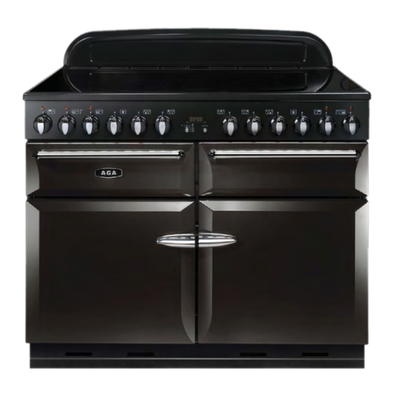
Summary of Contents for AGA Masterchef XL
- Page 1 MASTERCHEF USER GUIDE & INSTALLATION INSTRUCTIONS 110 Induction...
- Page 2 Each piece in the AGA Cookshop collection has been designed to offer the best possible performance, whether you cook with an AGA or not. Developed by experts, our range of cookware is designed for quality, performance and durability. The AGA Cookshop collection comprises cookware, kettles, bakeware, textiles and a variety of accessories.
-
Page 3: Table Of Contents
Contents Before You Start... Troubleshooting Installation and Maintenance Installation Peculiar Smells Dear Installer Ventilation Safety Requirements and Regulations Personal Safety Provision of Ventilation Hob Care Location of Cooker Cooker Care Positioning the Cooker Cooker Overview Moving the Cooker The Hob Repositioning the Cooker Following Connection The Glide-out Grill... -
Page 5: Before You Start
1. Before You Start... Personal Safety Thank you for buying this cooker. It should give you many years of trouble-free cooking if installed and operated Important information for pacemaker and implanted correctly. insulin pump users: The functions of this hob comply with Your cooker should give you many years of trouble-free the applicable European standards on electromagnetic cooking if installed and operated correctly. - Page 6 Always keep combustible materials, e.g. curtains, and Fig.1-1 flammable liquids a safe distance away from your cooker. DO NOT spray aerosols in the vicinity of the cooker while it is on. Cooking high moisture content foods can create a ‘steam burst’...
-
Page 7: Hob Care
Hob Care Fig.1-3 NEVER cook directly on the hob surface (Fig.1-2). DO NOT use the hob surface as a cutting board. DO NOT leave utensils, foodstuffs or combustible items on the hob when it is not is use (e.g. tea towels, frying pans containing oil). -
Page 8: Cooker Overview
2. Cooker Overview DocNo.020-0006 - Overview - 100DF - Prof+ Fig.2-1 Your induction cooker (Fig.2-1) has the following features: Fig.2-2 5 induction cooking zones A control panel A glide-out grill A multi-function oven A slow cook oven A fan oven The Hob Use only pans that are suitable for induction hobs. - Page 9 Never use a round-bottomed wok, even with a stand. Fig.2-4 The very best pans have bases that are very slightly curved Max: 1.85 kW Max: 1.85 kW Max: 1.85 kW up when cold (Fig.2-3). If you hold a ruler across the bottom Boost: 2.5 kW Boost: 3.0 kW Boost: 2.5 kW...
-
Page 10: Child Lock
Residual Heat Indicator, H automatic heat-up time at Power level 100% (min:sec) After use, a cooking zone will remain hot for a while as heat dissipates. When a cooking zone is switched off the residual 0:48 heat indicator symbol [H ], will appear in the display. This 2:24 shows that the cooking zone temperature is above 60 °C and may still cause burns. - Page 11 Low Temperature Setting, L1/L2 Fig.2-8 A & B linked Each cooking area is equipped with 2 low temperature settings: • L1 will maintain a temperature of about 40 °C – ideal for gently melting butter or chocolate. • L2 will maintain a temperature of about 90 °C – ideal for simmering (bring the pan to the boil and then select L2 to keep soups, sauces, stews, etc at an optimal simmer).
-
Page 12: The Glide-Out Grill
The Glide-out Grill Fig.2-9 CaUTION: This appliance is for cooking purposes only. It must not be used for other purposes, for example room heating. CaUTION: accessible parts may be hot when the grill is in use. Young children should be kept away. Open the door and pull the grill pan carriage forward using the handle (Fig.2-9). -
Page 13: The Ovens
The Ovens Fan oven cooking is particularly suitable for baking on several shelves at one time and is a good ‘all-round’ function. It may The clock must be set to the time of day before the left- be necessary to reduce the temperature by approximately hand oven will work. -
Page 14: The Fan Oven
Base Heat The Fan Oven This function uses the base element only. It will crisp The right-hand oven is a fan oven that circulates hot air up your pizza or quiche base or finish off cooking the continuously, which means faster, more even cooking. base of a pastry case on a lower shelf. -
Page 15: Operating The Ovens
Operating the Ovens Fig.2-12 Fan Oven Turn the oven knob to the desired temperature (Fig.2-12). The oven indicator light will glow until the oven has reached the temperature selected. It will then cycle on and off during cooking. Multi-function Oven The multi-function oven has two controls: a function selector and a temperature setting knob (Fig.2-13). -
Page 16: The Clock
The Clock Fig.2-16 ArtNo.300-0004 2-button clock annotated Setting the Time of Day The 2-knob LCD clock is shown in (Fig.2-16). When the clock is first connected, the display flashes ( 0.00 ) and ( alternately. To set the time, turn and hold the Timer knob to the clock symbol [ ... -
Page 17: Manual Cooking
The ‘stop time’ is displayed, followed by ‘AUTO’ . Set the oven Fig.2-24 Fig.2-25 to the cooking temperature you need. Turn the Timer knob to the ‘Auto’ setting. Art No. 301-0011 2BC ArtNo.301-0012 2BC Activating the key lock 1 Activating the key lock 2 When your cooking is finished, the beeper sounds. -
Page 18: Accessories
Accessories Fig.2-29 Oven Shelves Flat shelf Shelf guard In addition to the flat shelves, your cooker is supplied with a drop shelf (Fig.2-29). The drop shelf increases the possibilities for oven shelf spacing. Front The oven shelves can be easily removed and refitted. Pull the shelf forward until the back of the shelf is stopped by Shelf guard Drop shelf... -
Page 19: Cooking Tips
3. Cooking Tips DocNo.030-0010 - Cooking tips - 110 induction GENERIC Hints on Using Your Induction Cooker General Oven Tips If you have not used an induction cooker before please be The wire shelves should always be pushed firmly to the back aware of the following: of the oven. -
Page 20: Cooking Table
4. Cooking Table DocNo.031-0004 - Cooking table - electric & fan single cavity The oven control settings and cooking times given in the table below are intended to be used AS A GUiDE OnLy. Individual tastes may require the temperature to be altered to provide a preferred result. -
Page 21: Cleaning Your Cooker
5. Cleaning Your Cooker Isolate the electricity supply before carrying out any major Fig.5-1 cleaning. Allow the cooker to cool. NEVER use paint solvents, washing soda, caustic cleaners, biological powders, bleach, chlorine based bleach cleaners, coarse abrasives or salt. DO NOT mix different cleaning products – they may react together with hazardous results. -
Page 22: Glide-Out Grill
Glide-out Grill Fig.5-2 Before you remove any of the grill parts for cleaning. make sure that they are cool, or use oven gloves. The grill pan and trivet should be washed in hot soapy water. Alternatively, the grill pan can be washed in a dishwasher. After grilling meats or any foods that soil, leave to soak for a few minutes in the sink immediately after use. -
Page 23: Control Panel And Doors
Control Panel and Doors Fig.5-6 Avoid using any abrasive cleaners including cream cleaners. For best results, use a liquid detergent. The same cleaner can also be used on the doors, or alternatively, using a soft cloth wrung out in clean hot soapy water –... -
Page 24: Cleaning Table
Cleaning Table Cleaners listed (Table 5-1) are available from supermarkets or electrical retailers as stated. For enamelled surfaces use a cleaner that is approved for use on vitreous enamel. Regular cleaning is recommended. For easier cleaning, wipe up any spillages immediately. Hotplate Part Finish... -
Page 25: Troubleshooting
6. Troubleshooting DocNo.050-0001 - Troubleshooting - Induction GENERIC Interference with and repairs to the hob MUST NOT The cooling fan be carried out by unqualified persons. Do not try The induction hob incorporates a cooling fan. This to repair the hob as this may result in injury and cooling fan is active when either the grill or ovens damage to the hob. - Page 26 Food is cooking too slowly, too quickly, or burning Fig.6-1 Cooking times may differ from your previous oven. Check that you are using the recommended temperatures and shelf positions – see the oven ArtNo.324-0005 Oven light bulb cooking guide. Then adjust the settings according to your own individual tastes.
- Page 27 Taking care to protect your fingers with a glove in case Fig.6-3 the bulb should shatter, unscrew the old bulb. Screw in the new bulb clockwise and then screw the bulb cover back on. Turn on the electricity supply and check that the bulb now lights.
-
Page 28: Installation
INSTALLATION Check the appliance is electrically safe when you have finished. 7. Installation you will need the following equipment to complete the Dear Installer cooker installation satisfactorily: Before you start your installation, please complete the details • Multimeter: For electrical checks. below, so that, if your customer has a problem relating to your installation, they will be able to contact you easily. -
Page 29: Positioning The Cooker
INSTALLATION Check the appliance is electrically safe when you have finished. Positioning the Cooker Fig.7-1 Fig.7-1 shows the minimum recommended distance from the cooker to nearby surfaces. 75 mm 75 mm 650 mm The cooker should not be placed on a base. The hotplate surround should be level with, or above, any adjacent work surface. -
Page 30: Repositioning The Cooker Following Connection
INSTALLATION Check the appliance is electrically safe when you have finished. Lowering the Two Rear Rollers Fig.7-5 To adjust the height of the rear of the cooker, first fit a 13 mm spanner or socket wrench onto the hexagonal adjusting nut (Fig.7-5). -
Page 31: Fitting The Handles
INSTALLATION Check the appliance is electrically safe when you have finished. Fitting the Handles Fig.7-7 The handles for the grill and slow oven will require fitting as follows: Open the door. To keep the door open, either place a suitable weight on it or have someone hold it. -
Page 32: Electrical Connection
INSTALLATION Check the appliance is electrically safe when you have finished. Electrical Connection Fig.7-11 The cooker must be installed by a qualified electrician, in accordance with all relevant British Standards/Codes of Practice (in particular BS 7671), or with the relevant national and local regulations. -
Page 33: Final Fitting
INSTALLATION Check the appliance is electrically safe when you have finished. Final Fitting Fig.7-13 Fitting the 2-piece Plinth Fit the inner plinth to the bottom front of the cooker using the 5 screws provided (3x M5 screws in the lower edge, 2x No.8 screws in the each end) (Fig.7-13). -
Page 34: Circuit Diagrams
8. Circuit Diagrams artNo.095-0003 - Circuit diagram - 90 induction Circuit Diagram: Hob Earth N(6) On terminal block N(4) On terminal block Induction unit Hob display ArtNo.083-0011 - IN G5 2-phase - Circuit diagram L(2) L(3) On terminal block w/br Interface w/br w/br... -
Page 35: Circuit Diagram: Oven
Circuit Diagram: Oven P095199 Black Boot Black Boot P038434 P033458 P033458 Black Boot The connections shown in the circuit diagram are for single-phase. The ratings are for 230 V 50 Hz. Code Description Code Description Code Colour Grill thermostat Slow cook oven front switch Blue Grill element Slow cook oven elements... -
Page 36: Technical Data
DocNo.107-0023 - Technical data - 110DF - Classic DL 9. Technical Data INSTaLLER: Please leave these instructions with the User. DaTa BaDGE LOCaTION: Cooker back, serial number repeater badge below oven door opening. COUNTRY OF DESTINaTION: GB, IE. Connections Electric 230/400 V 50 Hz Dimensions Overall height... - Page 37 Notes...
- Page 38 Notes...
- Page 39 Dual Zone Refrigerator CAST IRON STOVES When you invest in an AGA stove, you are acquiring a piece of history, a talking point and a centrepiece for your home. AGA stoves are brought to you by the manufacturers of the world famous AGA range cooker.
- Page 40 Registered in England and Wales. Registration No. 354715 Registered Office: Juno Drive, Leamington Spa, Warwickshire, CV31 3RG AGA continuously seeks improvements in specification, design and production of products and thus, alterations take place periodically. Whilst every effort is made to produce up-to-date literature, this booklet should not be regarded as an infallible guide to current specification,...
Need help?
Do you have a question about the Masterchef XL and is the answer not in the manual?
Questions and answers