AGA SIX-FOUR SERIES - DC6 Owner's Manual
Six-four series
Hide thumbs
Also See for SIX-FOUR SERIES - DC6:
- User manual (60 pages) ,
- Owner's manual (60 pages) ,
- Manual (16 pages)
Table of Contents
Advertisement
AGA SIX-FOUR SERIES - DC6 (FFD)
OWNERS MANUAL - NATURAL GAS
DESN 512387 A
Comprising
Servicing, Installation & Users
Instructions
&
Cooking Guide
Remember, when replacing a part on this appliance, use only spare parts that you can be
assured conform to the safety and performance specification that we require. Do not use
reconditioned or copy parts that have not been clearly authorised by AGA.
PLEASE READ THESE INSTRUCTIONS BEFORE USING THIS APPLIANCE
For use in GB and IE
11/09 EINS 512335
Advertisement
Table of Contents

Related Manuals for AGA SIX-FOUR SERIES - DC6


Summary of Contents for AGA SIX-FOUR SERIES - DC6
-
Page 1: Cooking Guide
Remember, when replacing a part on this appliance, use only spare parts that you can be assured conform to the safety and performance specification that we require. Do not use reconditioned or copy parts that have not been clearly authorised by AGA. PLEASE READ THESE INSTRUCTIONS BEFORE USING THIS APPLIANCE... -
Page 2: Table Of Contents
CONTENTS SECTION PAGE INSTALLATION SECTION INSTALLATION TECHNICAL DATA FITTING AND PRODUCT DIMENSIONS ELECTRICAL CONNECTION CONNECTING TO GAS 9-11 PRESSURE TESTING LEVELLING AND MOBILITY WHEELS FITTING OF HOTPLATE CASTINGS AND PAN SUPPORTS13-17 SPLASHBACK USERS GUIDE GENERAL INFORMATION HEALTH AND SAFETY PRODUCT VIEW CONTROL PANEL GAS HOTPLATE 23-24... -
Page 3: Installation Section
Remember, when replacing a part on this appliance, use only spare parts that you can be assured conform to the safety and performance specification that we require. Do not use reconditioned or copy parts that have not been clearly authorised by AGA. -
Page 4: Installation
INSTALLATION WARNING: THIS APPLIANCE SHALL BE INSTALLED IN ACCORDANCE WITH THE REGULATIONS IN FORCE AND ONLY USED IN A WELL VENTILATED SPACE, READ THE INSTRUCTIONS BEFORE INSTALLING OR USING THIS APPLIANCE. PRIOR TO INSTALLATION, ENSURE THAT THE LOCAL DISTRIBUTION CONDITIONS (TYPE OF GAS AND GAS PRESSURE) AND THE ADJUSTMENTS OF THE APPLIANCE ARE COMPATIBLE. -
Page 5: Technical Data
TECHNICAL DATA HOTPLATE NATURAL GAS G20 - (APPLIANCE CATEGORY I L.H.F. R.H.F. R.H.R. L.H.R. CENTRE CENTRE FRONT REAR BURNER TYPE ULTRA-RAPID RAPID RAPID SEMI-RAPID SEMI-RAPID ULTRA-RAPID MAXIMUM HEAT 4.5 kW 3.0 kW 3.0 kW 1.75 kW 1.75 kW 5.0 kW INPUT INJECTOR MARKING MAIN... -
Page 6: Fitting And Product Dimensions
FITTING AND PRODUCT DIMENSIONS Any side wall above the cooker on either side shall be not less than 60mm horizontally from the cooker (Fig. 1). Surfaces over the top of the cooker must not be closer than 650mm. A minimum clearance of 1000mm must be available at the front of the cooker to enable it to be serviced. -
Page 7: Electrical Connection
ELECTRICAL CONNECTION ELECTRICAL CONNECTION IS LOCATED AT THE TOP RIGHT HAND SIDE OF THE APPLIANCE, BEHIND SIDE PANEL. DURING INSTALLATION REMOVE THE RIGHT HAND SIDE PANEL TO CONNECT ELECTRICAL SUPPLY. Remove 6 screws securing side panel to gain access to mains terminal. See Fig. 3 for location of cover. - Page 8 THREE PHASE CONNECTION - MINIMUM 2.5mm CABLE AND MUST COMPLY WITH THE LATEST EDITIONS OF THE LOCAL AND NATIONAL WIRING REGULATIONS. Fig. 2b DESN 512313...
-
Page 9: Connecting To Gas
CONNECTING TO GAS To allow ease of servicing and cooker mobility, an approved flexible 4ft hose should be fitted. Supply piping should not be less than R 1/2 (1/2” BSP). Connection is made to the R 1/2 (1/2” BSP) female threaded entry in the inlet block located just below the hotplate level on the rear right hand side of the cooker. - Page 10 COOKER STABILITY A stability bracket shall be secured firmly to the fabric of the building, when the appliance is connected to the gas supply by a flexible hose. For positioning of bracket (See Fig. 3). A safety chain must also be anchored firmly to the wall and cooker to prevent the flexible hose from straining, when the cooker is withdrawn for servicing.
-
Page 11: Pressure Testing
POSITION OF GAS BAYONET ON WALL (locate in shaded areas) IMPORTANT: THE GAS SUPPLY CONNECTION AT THE WALL MUST NOT PROJECT OUT FROM THE WALL BY MORE THAN 45MM, SO THAT IT DOES NOT FOUL WITH THE BACK OF THE COOKER. Fig. -
Page 12: Levelling And Mobility Wheels
LEVELLING AND MOBILITY WHEELS INSTALLATION/LEVELLING The cooker is fitted with mobility rollers, two at the rear and two at the front. The DC6 is designed to stand on a flat and level surface, however, any unevenness may be overcome by adjusting the four levelling feet, one at each corner of the base plate. The adjusting screws are accessed by removing left and right hand hotplate castings (See section ‘To Remove Hotplate Castings - Servicing Section Page 50). -
Page 13: Fitting Of Hotplate Castings And Pan Supports13-17
FITTING OF HOTPLATE CASTING AND PAN SUPPORTS HOTPLATE CASTINGS 1. Attach earth cable from centre casting to cooker chassis and locate over burner bodies. Repeat for LH and RH castings and that the gaskets are fitted where the outer castings overlap centre castings. - Page 14 3. Fit and secure six burner rings using M4 screws on rear left hand, front centre, front right hand and rear right hand burners. Use No.6 3/8 screw on front left hand and centre rear burners. (See Fig. 6C). NOTE: The fitting of LH and centre burners are the same as shown in Fig. 6B. Fig.
- Page 15 ASSEMBLY RAPID SEMI-RAPID BURNERS BURNER CAP BURNER HEAD ELECTRODE Fig. 7B DESN 511618 FITTING BURNER CAP - RAPID AND SEMI-RAPID BURNERS BURNER CAP RETAINING LUGS Fig. 7C DESN 511617...
- Page 16 It is very important for the performance and reliability of the hob that the pan supports are fitted in accordance with the AGA SIX-FOUR SERIES - DC6 OWNERS MANUAL. To help identify the correct location of the pan supports, the centre rear pan support has been uniquely designed with a tag, as shown.
-
Page 17: Splashback
Fig. 8C DESN 513716 TO ADJUST PAN SUPPORT LEVEL Loosen retaining nut using 8mm spanner (See Fig. 8C). To prevent rocking adjust the pan support foot using 2.5mm allen key. Check pan support is level with opposing pan supports. Retighten retaining nut. HANDRAIL FITTING Position handrail assembly onto locating studs at each end of facia. -
Page 18: Users Guide
Users Guide... -
Page 19: General Information
Any alteration that is not approved by Aga could invalidate the approval of the appliance, operation of the warranty and could affect your statutory rights. In the interests of safety and effective use, please read the following before using your new Aga appliance. -
Page 20: Health And Safety
HEALTH & SAFETY APPLIANCE YOUNG CHILDREN SHOULD BE KEPT AWAY FROM THE APPLIANCE AS SOME SURFACES CAN BECOME HOT TO TOUCH. During use the appliance can become hot. Care should be taken to avoid touching heating elements inside the oven. Deep Fat Frying Use a deep pan, large enough to completely cover the appropriate heating area. -
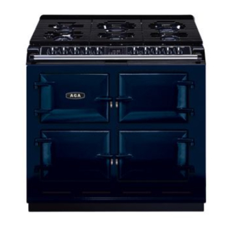
Page 21: Product View
Fig. 10 DESN 512395 B... -
Page 22: Control Panel
CONTROL PANEL The GAS HOTPLATE CONTROL KNOBS can only be rotated anti-clockwise from the OFF position. Symbol - Ignition Setting Large Flame Symbol - High Setting Small Flame Symbol - Low Setting (See ‘HOTPLATE’ section). Fig. 11 DESN 513717 The GRILL ELEMENT CONTROL KNOB can be rotated in either direction. Clockwise Full on, with both elements on Anti-clockwise... -
Page 23: Gas Hotplate
GAS HOTPLATE The hotplate has six gas burners: front left - ultra rapid (wok) burner - rated at 4.5 kW rear left and front centre - semi-rapid burners - each rated at 1.75 kW rear right and front right - rapid burner - each rated at 3.0 kW centre rear - ultra rapid burner - rated at 5.0 kW The semi rapid burners are especially suited for use with small pans and gentle simmering or poaching. - Page 24 SOME SAFETY POINTS Simmering aids such as asbestos or mesh mats are not recommended. They can impede burner performance, damage the pan supports and waste fuel. Commercially available foil spillage aids are unnecessary on this cooker and could effect the combustion. Some ‘Wok’...
-
Page 25: To Fit Pan Supports
It is very important for the performance and reliability of the hob that the pan supports are fitted in accordance with the AGA SIX-FOUR SERIES - DC6 OWNERS MANUAL. To help identify the correct location of the pan supports, the centre rear pan support has been uniquely designed with tag, as shown. -
Page 26: Setting Up The Cooker For Use
SETTING UP THE COOKER FOR USE Before you can use the lower left hand oven of the appliance it will be necessary to set the ‘time of day’ clock. This is a 24 hour clock, and when the power supply is initially switched on, or after an interruption in supply, the clock will show AUTO and 0.00 alternately. -
Page 27: Griddle Plate
GRIDDLE PLATE The griddle plate is designed for use ONLY on your Aga DC6 Natural Gas cooker. It MUST only be used on the right hand rapid burners. It should be positioned on the pan supports as below to ensure correct and safe operation. -
Page 28: Simmering Oven
USING THE SIMMERING OVEN SETTING Points to bear in mind when preparing food. For best results use the Aga Stainless Steel Cookware, Aga recommend AG30012 - Saute Casserole Dish and Lid. Do not place dish directly on to the oven base. Always place onto shelf supplied. See Fig. -
Page 29: Simmering Oven Recipes
Simmering Oven Simmering Oven • Simmering Oven • Simmering Oven • Simmering Oven • Simmering Oven • IDEAS FOR THE SIMMERING OVEN Many favourite recipes can be adapted for this type of cooking. Check that chosen ovenware will fit into the oven. Meal 1 6 - 8 hours cooking Ragout of Beef in Ale... - Page 30 Simmering Oven • Simmering Oven • Simmering Oven • Simmering Oven • Simmering Oven • Simmering Oven • Simmering Oven Meal 2 6 - 8 hours cooking Roast Fillet of Lamb Dauphinoise Potatoes Bread and Butter Pudding Recipes Roast fillet of Lamb 900g - 1.25 kg (2-2 lbs) lamb Season and wrap the lamb in foil.
- Page 31 Simmering Oven • Simmering Oven • Simmering Oven • Simmering Oven • Simmering Oven • Simmering Oven • Simmering Oven • Meal 3 6 - 8 hours cooking Gammon and Apricot Pie Braised Red Cabbage St. Clements Pudding Recipes Gammon and Apricot Pie 2 gammon rashers approx 15mm ( ”) thick Remove the rind from the gammon.
- Page 32 Simmering Oven • Simmering Oven • Simmering Oven • Simmering Oven • Simmering Oven • Simmering Oven • Simmering Oven • Meal 4 Chilli Con Carne Frangipane and Apple Pudding Recipes Chilli Con Carne 450g (1lb) minced beef Brown the minced beef in a flame proof casserole dish. 1 x 400g (14oz) tin tomatoes Stir in the spice mix.
-
Page 33: The Grill
THE GRILL THE GRILL COMPARTMENT DOOR MUST BE KEPT OPEN WHEN THE GRILL IS ON. CAUTION: Accessible parts may be hot when the grill is in use. Young children should be kept away. The very high speed instant grill is divided into two areas to save energy and to suit individual grilling requirements. -
Page 34: The Ovens
THE OVENS General The ovens and grill compartment are fitted with side and back self cleaning panels. The roof of the oven is also self-cleaning enamel. The shelves are designed to be non-tilt. To remove a shelf, lift clear of the side notches and slide forward. To replace a shelf, insert into the oven with the short prongs at the rear, facing upwards. -
Page 35: Oven Cooking Guide
OVEN COOKING GUIDE Cooking Hints Shelf positions are counted from the bottom. Put dishes in the centre of the shelf. When using the fan oven, reduce conventional oven settings by 10ºC - 20ºC and in some cases, cooking time by up to 10 minutes for every hour. It is important to check that food is piping hot before serving. - Page 36 Conventional Oven Conventional Oven • Conventional Oven • Conventional Oven • Conventional Oven The right hand upper oven is a conventional oven which means that the heating elements are in the top and under the base of the oven compartment. The cooking charts are a general guide but times and temperatures may vary according to individual recipes.
- Page 37 • Conventional Oven • Conventional Oven • Conventional Oven • Conventional Oven • Conventional Oven • Conventional Oven • SHELF FOOD SETTING °C APPROXIMATE COOKING TIME POSITION Meringue Toppings 140 - 150 1 or 2 45 mins Meringues 100 - 110 3 - 4 hours - Turn meringues over as soon as they are set Yeast Mixture Bread - loaves...
- Page 38 Fan Oven • F a n O v e n • F a n O v e n • F a n O v e n • F a n O v e n • F a n O v e n • F a n O v e n • F a n O v e n • The left hand lower oven is a fan oven, which means that the air is circulated to create an even temperature throughout.
- Page 39 Fan Oven • Fan Oven • Fan Oven • Fan Oven • Fan Oven • Fan Oven • Fan Oven • Fan Oven • Fan Oven • Fan Oven • APPROXIMATE COOKING TIME FOOD SETTING °C Meringue Toppings 45 mins Meringues 80 - 90 3 - 4 hours - Turn meringues over as soon as they are set...
-
Page 40: The Minute Timer
THE MINUTE TIMER The minute timer works separately from the time of day clock and can be set to time periods from 1 minute to 23:59 hours. Only a one handed operation is required. SETTING THE MINUTE TIMER 1. Press the MINUTE TIMER button the bell symbol and 0.00 will be displayed. -
Page 41: Automatic Cooking Control
AUTOMATIC COOKING CONTROL This can be used to set an automatic cooking programme in the bottom left fan oven only. It switches the electricity on and off at the pre-set times. The maximum length of cooking programme which can be set is 23 hours and 59 minutes e.g. delay time + cooking time = maximum 23 hours and 59 minutes. -
Page 42: Cleaning And Caring For Your Cooker
THE FOLLOWING PARTS ARE NOT DISHWASHER SAFE: Aluminium burner heads (LHR, CF, RHR, RHF). IMPORTANT: Aga recommend Vitreous Enamel Association approved cleaners for cleaning the vitreous enamelled surfaces of this product. But they are unsuitable for use on: chrome and stainless steel components, hand-rails and their brackets. - Page 43 CLEANING & CARING FOR YOUR COOKER COOKER PART AND FINISH CLEANING METHOD Vitreous Enamel Clean with a damp cloth and hot soapy water. Stubborn stains can be removed with Grill - base only mild cream, paste or liquid cleaners, or by Hotplate gently rubbing with a well moistened, Control panel...
- Page 44 COOKER PART AND FINISH CLEANING METHOD Heat-Clean Enamel This special enamel has a continuous cleaning action, which works best if a pattern Fan oven, Conventional oven, Simmering of low and high temperature cooking is oven: sides top and back followed. By using low temperature roasting, Grill compartment: sides and back excessive fat splashes can be avoided.
- Page 45 Oven Shelves - These shelves are designed to slide out STOP ON SHELF MUST PROJECT SHELF STOP AND ANTI TILT BRACKET DESN 511867 Refit as follows: Locate in guide as above. DESN 511866 Please Note: Shelf slides out to stop position. Fig.
- Page 46 ASSEMBLY OF RAPID AND SEMI-RAPID BURNER BURNER CAP BURNER HEAD ELECTRODE Fig. 19 DESN 511618 FITTING BURNER CAP - RAPID AND SEMI-RAPID BURNER BURNER CAP RETAINING LUGS Fig. 20 DESN 511617...
- Page 47 WOK BURNER Fig. 21 DESN 513512 ULTRA RAPID BURNER Fig. 21B DESN 513714...
-
Page 48: Servicing Section
Remember, when replacing a part on this appliance, use only spare parts that you can be assured conform to the safety and performance specification that we require. Do not use reconditioned or copy parts that have not been clearly authorised by AGA. -
Page 49: Servicing
SERVICING In the event of your appliance requiring maintenance, please call Aga Service or contact your authorised distributor/stockist. Your cooker must only be serviced by a qualified Gas Safe Registered Engineer from an authorised distributor or stockist. Do not alter or modify the cooker. - Page 50 WARNING: WHEN SERVICING OR REPLACING GAS CARRYING COMPONENTS, DISCONNECT GAS SUPPLY TO APPLIANCE AND AFTER COMPLETION CHECK APPLIANCE FOR GAS SOUNDNESS. WARNING: WHEN SERVICING OR REPLACING COMPONENTS, ISOLATE THE APPLIANCE FROM THE ELECTRIC SUPPLY AND BEFORE RECONNECTING, CHECK FOR ELECTRICAL SUPPLY. TO REMOVE HOTPLATE Isolate from electric supply.
- Page 51 Fig. 24 DESN 512407 B TO REMOVE SIDE PANELS Isolate from electric supply. Lower the cooker onto the rollers by turning the adjusting feet fully anti-clockwise. NOTE: It may be necessary to disconnect the flexible gas connection to allow the cooker to be withdrawn from between the kitchen units.
- Page 52 TO REMOVE HANDRAIL (SEE FIG. 25) Loosen 2 grub screws, one at each end of hand rail (see fig. 25) using 2 mm socket key. Slide handrail forwards, off locating studs. TO REMOVE TIMER Isolate from electric supply. Proceed as ‘TO REMOVE HOTPLATE CASTINGS’. Remove fixing screws (4).
- Page 53 TO REMOVE GAS TAPS/IGNITION SWITCHES Isolate from electric and gas supply. Proceed as ‘TO REMOVE HOTPLATE’. Proceed as ‘TO REMOVE FACIA’. Disconnect gas rail feed pipe (19mm nut). (See Fig. 28). Disconnect all gas connections to taps (5 nuts - 13mm, 14mm & 19mm). Remove (4) screws fixing gas rail.
- Page 54 TO REMOVE GRILL REGULATOR Isolate from electric supply. Proceed as ‘TO REMOVE FACIA CASTINGS’. Remove two screws securing control to control mounting panel. Withdraw control and cables taking care not to strain the cables. Disconnect cables from the control. NOTE: Take care to identify terminations. Re-assemble in reverse order.
- Page 55 TO REMOVE ELECTRODES (LHR, CF, CR, RHR, RHF BURNERS) Isolate from electric supply. Proceed as ‘TO REMOVE THE HOTPLATE’. Proceed as ‘TO REMOVE SPARK GENERATOR’ disconnect the appropriate electrode lead. Withdraw clip securing electrode to burner and withdraw lead and electrode (See Fig. 30). Re-assemble in reverse order.
- Page 56 Fig. 31 DESN 513530 TO REMOVE THERMOCOUPLE (LHF BURNER) Isolate from electric supply. Proceed as ‘TO REMOVE THE HOTPLATE’. Undo the nut fixing the thermocouple in place. Push the thermocouple down and pull out from under the burner. Disconnect the other end of the thermocouple cable from the gas valve. This is a push on jack connector.
- Page 57 TO REMOVE THERMOCOUPLE (LHR, RHR, RHF BURNERS) Isolate from electric supply. Proceed as ‘TO REMOVE THE HOTPLATE’. Undo the nut fixing the thermocouple in place. Push the thermocouple down and slide to the side to remove from the burner. Disconnect the other end of the thermocouple cable from the gas valve, this is a push on electrical terminal.
- Page 58 TO REMOVE ELEMENTS (RH OVENS) Isolate from electrical supply. Proceed as ‘TO REMOVE OVEN AND GRILL LINERS’. Remove oven base panel (1) screw at the rear of the oven. Lift out base panel. Remove oven element fixing screws (2) at the rear of the oven and flex elements to remove from location bracket, pull forwards to expose terminal connections.
-
Page 59: Wiring Diagram
WIRING DIAGRAM - AGA DC6... - Page 60 For further advice or information please contact your local distributor/stockist With Aga’s policy continuous product improvement, the Company reserves the right to change specifications and make modifications to the appliance described at any time. Manufactured by Station Road Ketley Telford...
Need help?
Do you have a question about the SIX-FOUR SERIES - DC6 and is the answer not in the manual?
Questions and answers