AGA Six Four Series Assembly Instructions Manual
Hide thumbs
Also See for Six Four Series:
- Assembly instructions manual (9 pages) ,
- Owner's manual (36 pages)
Advertisement
Quick Links
AGA
AGA
(with ceramic hob)
(with ceramic hob)
assembly instructions for models supplied modular
Specification
Total fully assembled weight ---
Power Supply ---
Maximum electrical load ---
Hotplate
Front left ---
Rear left ---
Front centre ---
Rear centre ---
Front right ---
Rear right ---
Ovens
Conventional Oven ---
Fan Oven ---
Simmering Oven ---
Grill ---
s.t 6.05
sixfourassbly2
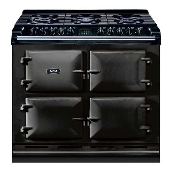
Six Four Series
Six Four Series
218kg
230V 50Hz
16.9 kW
0.75 - 2.2 kW
1.2 kW
1.2 kW
0.75 - 2.2 kW
1.5 kW
1.5 kW
2.0 kW
2.0 kW
0.9 kW
2.2 kW
Single or 3 Phase
Advertisement

Subscribe to Our Youtube Channel
Related Manuals for AGA Six Four Series


Summary of Contents for AGA Six Four Series
- Page 1 Six Four Series Six Four Series (with ceramic hob) (with ceramic hob) assembly instructions for models supplied modular Specification Total fully assembled weight --- 218kg Power Supply --- 230V 50Hz Single or 3 Phase Maximum electrical load --- 16.9 kW...
- Page 2 Clearances:- Refer to diagram overleaf Where the Aga is to be ‘slot’ fitted, a gap of 3mm is recommended each side, to allow the product to slide in easy. See dimension ’B’ Dimension ‘A’ 60mm, is the clearance to be provided against any side wall which extends above the level of the hob, to allow for protruding utensil handles.
- Page 3 Six Four series (Ceramic Hob) Six Four series (Ceramic Hob) assembly instructions for modular models assembly instructions for modular models...
- Page 4 Six Four series (Ceramic Hob) Six Four series (Ceramic Hob) assembly instructions for modular models assembly instructions for modular models 1 phase connections Cable entry position 3 phase connections (live links removed) Assembly procedure:- 1. Check that all 5 cartons...
- Page 5 Six Four series (Ceramic Hob) Six Four series (Ceramic Hob) assembly instructions for modular models assembly instructions for modular models Remove rear panel (7 screws) From the rear of the Front plate. Remove four outer screws but leave the two centre ones loosely in place.
- Page 6 Six Four series (Ceramic Hob) Six Four series (Ceramic Hob) assembly instructions for modular models assembly instructions for modular models Fasten the hotplate chassis down to the the main assembly. 4 screws. Identify and unwrap the three oven ther- mostat capillarys.
- Page 7 Six Four series (Ceramic Hob) Six Four series (Ceramic Hob) assembly instructions for modular models assembly instructions for modular models Top right Top right Plug in the two multi-way plugs. They are biased and will only fit into their correct sockets.
- Page 8 Six Four series (Ceramic Hob) Six Four series (Ceramic Hob) assembly instructions for modular models assembly instructions for modular models Refit side panels. Note that they drop down into the base then slide forward into posi- tion. Slot splashback into its sockets Cooker may now be rolled into its final position.
- Page 9 Six Four series (Ceramic Hob) Six Four series (Ceramic Hob) assembly instructions for modular models assembly instructions for modular models Push-fit the neons into their respective posi- tions on the front fascia. Remove the bracket from the back of the time clock (2 screws) Connect the multi-way plug.
Need help?
Do you have a question about the Six Four Series and is the answer not in the manual?
Questions and answers