Sign In
Upload
Download
Table of Contents
Contents
Add to my manuals
Delete from my manuals
Share
URL of this page:
HTML Link:
Bookmark this page
Add
Manual will be automatically added to "My Manuals"
Print this page
×
Bookmark added
×
Added to my manuals
Manuals
Brands
Lantech Manuals
Switch
IES-3416DSFP
User manual
Lantech IES-3416DSFP User Manual
Hide thumbs
1
2
3
4
Table Of Contents
5
6
7
8
9
10
11
12
13
14
15
16
17
18
19
20
21
22
23
24
25
26
27
28
29
30
31
page
of
31
Go
/
31
Contents
Table of Contents
Bookmarks
Table of Contents
Table of Contents
Chapter 1 Introduction
Hardware Features
Chapter 2 Hardware Description
Physical Dimension
IP Protection
LED Indicators
Chapter 3 Hardware Installation
Hardware Installation
DIN-Rail Mounting
Wall Mount Plate Mounting
Wiring the Power Inputs
Wiring the Fault Alarm Contact
Cabling
Chapter 4 Network Application
ITU G.8032 Scheme
Ring Coupling
Multiple Rings
Dual Homing
Chain
Chapter 5 Console Management
Connecting to the Console Port
Login in the Console Interface
Advertisement
Quick Links
Download this manual
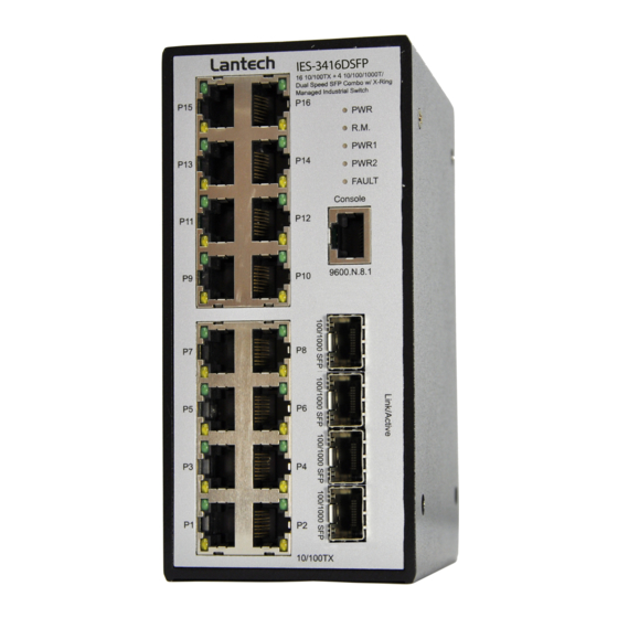
IES-3416DSFP
IPES-3416DSFP
16 10/100TX (PoE at/af) + 4 Dual Speed SFP L2+ Industrial
Managed Switch w/ Enhanced G.8032 ring
User Manual (Hardware)
Aug. 2017
Table of
Contents
Previous
Page
Next
Page
1
2
3
4
5
Advertisement
Table of Contents
Need help?
Do you have a question about the IES-3416DSFP and is the answer not in the manual?
Ask a question
Questions and answers
Related Manuals for Lantech IES-3416DSFP
Switch Lantech IES-3208C User Manual
8 (7)10/100tx + 2(3) 10/100/1000t/dual speed sfp combo and (8/7 poe at/af) (mode a/mode b)industrial managed switch w/itu g.8032 ring (141 pages)
Switch Lantech IPES-3424DSFP-2P User Manual
(26 pages)
Switch Lantech IPES-3424DSFP-2P-PT User Manual
(26 pages)
Switch Lantech IES-3 Series User Manual
Ip30-rated din rail l2+ industrial managed switch (26 pages)
Switch Lantech IES-3408GSFP User Manual
Ip30-rated din rail l2+ industrial managed switch (26 pages)
Switch Lantech IES-2208CA User Manual
8 10/100tx + 2 10/100/1000t/dual speed sfp combo managed industrial switch (139 pages)
Switch Lantech IES-0008-M12 User Manual
8 10/100tx ip41 rated industrial switch w/m12 connectors (16 pages)
Switch Lantech IES-2208C User Manual
8 10/100tx + 2 10/100/1000t/mini-gbic combo with x-ring l2 managed industrial switch (115 pages)
Switch Lantech IPES-5408T User Manual
8 10/100tx + 4 1000t l2+ (w/8 poe at/af) industrial managed switch w/itu g.8032 ring (305 pages)
Switch Lantech IPES-5408T-X-IGN Series User Manual
Industrial managed ethernet switch (21 pages)
Switch Lantech IES-22812F-2P User Manual
12 100fx + 8 10/100tx + 2 1000 sfp industrial power station l2 plus managed switch (154 pages)
Switch Lantech IPES-5222T Series User Manual
22 10/100tx + 2 1000t l2+ (w/8 poe at/af) industrial managed switch w/enhanced g.8032 ring (30 pages)
Switch Lantech IPES-0204DFT-4 User Manual
Industrial unmanaged switches (28 pages)
Switch Lantech IPES-5416T Series User Manual
16 10/100tx + 4 1000t l2+ (w/8 or 16 poe at/af) industrial managed switch w/itu g.8032 ring (34 pages)
Switch Lantech IGS-0016 User Manual
Industrial unmanaged ethernet switch (20 pages)
Switch Lantech IES Series User Manual
Ip30-rated l2 industrial managed switch w/itu g.8032 ring (29 pages)
This manual is also suitable for:
Ipes-3416dsfp
Table of Contents
Print
Rename the bookmark
Delete bookmark?
Delete from my manuals?
Login
Sign In
OR
Sign in with Facebook
Sign in with Google
Upload manual
Upload from disk
Upload from URL


Need help?
Do you have a question about the IES-3416DSFP and is the answer not in the manual?
Questions and answers