Table of Contents
Advertisement
Quick Links
Instructions
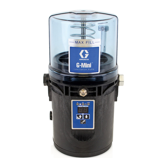
G-Mini
For dispensing NLGI Grades #000 to #2 greases. For professional use only.
Not approved for use in explosive atmospheres or hazardous (classified) locations.
Models, page 3
4061 psi (28 MPa, 280 bar) Maximum Working Pressure
Important Safety Instructions
Read all warnings and instructions in this
manual before using the equipment.
Save these instructions.
™
Pump
3A6714B
EN
Advertisement
Table of Contents

Related Manuals for Graco G-Mini Series


Summary of Contents for Graco G-Mini Series
- Page 1 Instructions ™ G-Mini Pump 3A6714B For dispensing NLGI Grades #000 to #2 greases. For professional use only. Not approved for use in explosive atmospheres or hazardous (classified) locations. Models, page 3 4061 psi (28 MPa, 280 bar) Maximum Working Pressure Important Safety Instructions Read all warnings and instructions in this manual before using the equipment.
-
Page 2: Table Of Contents
Technical Specifications ....32 Harsh Environments......... 8 Graco Standard Warranty ....34 Wiring and Installation Diagrams....9 Manual Run Button . -
Page 3: Models
Models Models Reservoir Voltage Cycle Pump Non- Power Feedback Element Model 0.5 L Controller Controller 12VDC 24VDC Input Level Input Quantity Heater 25R800 25R801 25R802 25R803 25R804 25R805 25R806 25R807 25R808 25R809 25R810 3A6714B... -
Page 4: Warnings
Warnings Warnings The following warnings are for the setup, use, maintenance, and repair of this equipment. The exclamation point symbol alerts you to a general warning and the hazard symbols refer to procedure-specific risks. When these symbols appear in the body of this manual or on warning labels, refer back to these Warnings. Product-specific hazard symbols and warnings not covered in this section may appear throughout the body of this manual where applicable. - Page 5 Warnings WARNING PRESSURIZED EQUIPMENT HAZARD Over-pressurization can result in equipment rupture and serious injury. • A pressure relief valve is required at each pump outlet. • Follow the Pressure Relief Procedure in this manual when servicing equipment. PLASTIC PARTS CLEANING SOLVENT HAZARD Many cleaning solvents can degrade plastic parts and cause them to fail, which could cause serious injury or property damage.
-
Page 6: Installation
Installation Installation Component Identification . 1: Key: Reservoir Venting Tube Follower Plate Pump Element Zerk Inlet Fill Fitting Cycle Indicator Connector (Controller model only) CPC Connector Controller Return to Reservoir 3A6714B... -
Page 7: Typical Installation
Installation Typical Installation Divider Installation Remote . 2: CSP Valve Installation with Bracket . 3: Connection to fused power source Pressure relief valve (required for each outlet)* See Pressure Relief Valves, page 12 Proximity switch cable Series progressive divider valves (Divider Installation) Connection to lube points Proximity switch, see page 11 Bracket, see page 8... -
Page 8: Choose An Installation Location
• Refer to the two mounting hole layouts provided in Fuse kits are available from Graco. The following table the Mounting Pattern section of this manual, page identifies the correct fuse to use for the input voltage and the corresponding Graco Kit number. -
Page 9: Wiring And Installation Diagrams
Installation Wiring and Installation Diagrams Power CPC DC - 5 Wire (Non-Controller) NOTE: Wire colors provided on these pages refer only to the Graco power cable. NOTICE Pin Out The stirring paddle should rotate clockwise (as viewed from the top) (F . - Page 10 Installation Power CPC DC - 5 Wire (Controller) Divider Valve Indicator Cycle Inputs (M12) See Technical Specifications, page 32 for ratings. Pin Out Not Used Not Used -VDC Black +VDC LED+ White Button Orange Not Used Not Used LED- Green 3A6714B...
-
Page 11: Manual Run Button
Installation Part No. 124333: Cable Pin Out (M12) for Manual Run Button 5 m Cable Part No. Description Wire Colors (F . 8) 25C981 Manual Run Button, 12V 25C982 Manual Run Button, 24V Item No. Color Brown White Proximity Switch Blue Black NOTE: Reference ILE buyer’s guide for appropriate PNP... -
Page 12: Setup
• Install a pressure relief valve before any auxiliary fitting. NOTE: A pressure relief valve may be purchased from Graco. See Pressure Relief Valves, page 12. Pressure Relief Valves Part No. Description 571028 Kit, Adj. Pressure Relief... -
Page 13: Set Pump Outlet Volume
18A317 0.0915 attached. NOTE: A spacer is required for operation. Only one Graco spacer can be used at a time. The pumps from NOTICE the factory have a spacer (25N814) installed on the • Always clean fitting (E) with a clean dry cloth pump element. -
Page 14: Change Greases
Setup 1. Connect the fill hose to the Zerk Inlet Fill Fitting (E) NOTE: The venting tube (B) should not be used as an . 11). overfill indicator (F . 12). . 11 2. For higher viscosity fluids, start the pump, per the . -
Page 15: Priming
Setup Priming It is not necessary to prime the pump every time the pump is filled. The pump only requires priming the first time it is used, or if it is allowed to run dry. 1. Loosen the pump element fitting (F . -
Page 16: Non Controller Operation
• In most cases, Pump OFF (Rest) Time should be twice as long as Pump ON (Run) time. If alternative ON / OFF times are required, contact Graco Cus- tomer Service for assistance. Typical Low-Level Output Response with Low-Level Fluid . -
Page 17: Controller Operation
Controller Operation Controller Operation Control Panel Overview (F . 17) ON TIME OFF TIME • In SETUP MODE, the LED illumi- • In SETUP MODE, the LED illuminates when OFF TIME duration is nates when ON TIME duration or set up. cycles are set up. -
Page 18: Run Mode
Controller Operation The controller operates in two modes; RUN MODE and SETUP MODE SETUP MODE. Each mode has multiple functions. Press both the UP and DOWN arrow buttons RUN MODE together for 3 seconds to enter SETUP MODE. RUN MODE performs two functions while monitoring Alert/Alarm conditions: ON TIME and OFF TIME. -
Page 19: On Time Configuration (Cycles)
Controller Operation 3. Press the UP or DOWN After the ENTER button is arrows to select the sec- pressed, the second digit ond digit. begins to blink. The ON LED remains lighted. 4. Press the ENTER button This confirms that the second to save the selection. -
Page 20: Advanced Programming
Controller Operation After the ENTER button is After entering ADVANCED PROGRAMMING, if no activ- pressed, the second digit ity is detected for 60 seconds, a timeout occurs and the begins to blink. The OFF controller resumes RUN MODE. LED and HH dot remain lighted. - Page 21 Controller Operation Entering a PIN Code in the Controller OF (OFF) - Select OF to con- figure the controller to not After the controller is configured for PIN entry, to access require a PIN code. Press the SETUP MODE: ENTER button again to set the OF (OFF) option.
- Page 22 Controller Operation A2 – Prelube and Delay The Low-Level Auto Clear is an OF (OFF) or On (ON) selection. The Prelube Delay option configures the controller to set the amount of time before the Prelube cycle begins. The • OF (OFF) (default) – Upon power cycle, the control- duration of time begins after power has been restored to ler will remain in its current Low-Level Alarm state.
-
Page 23: Alerts And Alarms
Alerts and Alarms Alerts and Alarms Alarms The controller monitors and displays two types of events: Alerts and Alarms. Alarms cause the lubrication cycle to stop. Alarms can trigger immediately or can be the result of an escalated Alerts Alert. Alarms must be cleared immediately. Alerts do not cause the lubrication cycle to stop. -
Page 24: Alert And Alarm Scenarios
Cancel Button for 4 sec- onds. System An internal fault has occurred. Attempt a power cycle of the device. Fault The controller may not be recover- If the alarm does not clear, contact Graco able from this state. Customer Service. 3A6714B... -
Page 25: Troubleshooting
Reservoir is being pressurized Ensure that the vent tube is not during filling. plugged. If the problem persists, contact Graco Customer Service or your local Graco distributor for assistance. The external controller is Motor failure. Replace the motor. -
Page 26: Maintenance
Maintenance Maintenance Frequency Component Required Maintenance Daily and at Refill Fill Fittings Keep all of the fittings clean using a clean dry cloth. Dirt and/or debris can damage the pump and/or the lubrication system. Daily Pump Unit and Reservoir Keep pump unit and reservoir clean using a clean dry cloth. -
Page 27: Repair
Repair Repair All electrical wiring must be done by a qualified electrician and comply with all local codes and regulations. Reservoir Kits Kit No. Description 26C943 Kit Replacement, Reservoir, 1L 26C945 Kit Replacement, Reservoir, 0.5L Kit Replacement, Reservoir, Follower 26C944 Plate, 1L Kit Replacement, Reservoir, Follower 26C946... -
Page 28: Parts
Parts Parts 4a, 4b 41a, 41b, 41c 25a, 25b 32a, 32b Torque to 13 in-lb (1.5 N•m) Torque to 65 in-lb (7.3 N•m) Torque to 23 in-lb (2.6 N•m) 3A6714B... - Page 29 Parts Part No./Description Ref. Part Description Qty. Ref. Part Description Qty. 100721 Plug, 1/4 npt, HEX socket Reservoir, 1.0 Liter, included in 123741 Nipple kits 26C943, 26C944 - Model 25R800, 25R801, 25R802, Label, overlay, BLK - 25R803, 25R804, 25R805, Model 25R800, 25R802, 25R807, 25R806 25R809 Reservoir, 0.5 Liter, included in...
-
Page 30: Dimensions
Dimensions Dimensions Height - A Width - B Depth - C Model Inches Inches Inches 0.5L 10.9 27.7 6.97 17.7 6.57 16.7 12.2 31.0 6.97 17.7 6.57 16.7 3A6714B... -
Page 31: Pump Mount
Dimensions Pump Mount CSP Valve Bracket Mount Universal Bracket Mount 3A6714B... -
Page 32: Technical Specifications
Technical Specifications Technical Specifications G-Mini Pump Metric Maximum fluid working pressure 4061 psi 28 MPa, 280 bar Power 12 VDC 9-16 VDC; 9.5 A current, 114 W, inrush/locked rotor 12 A 24 VDC 18-32 VDC; 6.5 A current, 156 W, inrush/locked rotor 7.5 A Inputs - Proximity Switch PNP Style Switch and Cable Only Pump Voltage: 12 VDC... - Page 33 Technical Specifications California Proposition 65 WARNING: This product can expose you to chemicals known to the State of California to cause cancer and birth defects or other reproductive harm. For more information, go to www.P65warnings.ca.gov. 3A6714B...
-
Page 34: Graco Standard Warranty
With the exception of any special, extended, or limited warranty published by Graco, Graco will, for a period of twelve months from the date of sale, repair or replace any part of the equipment determined by Graco to be defective.
Need help?
Do you have a question about the G-Mini Series and is the answer not in the manual?
Questions and answers