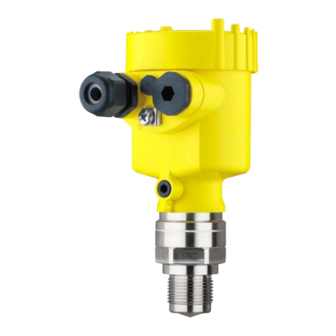
Vega VEGAPULS 64 Quick Setup Manual
Radar sensor for continuous level measurement of liquids
Hide thumbs
Also See for VEGAPULS 64:
- Operating instructions manual (100 pages) ,
- Quick setup manual (25 pages) ,
- Mounting instructions (24 pages)

Subscribe to Our Youtube Channel
Related Manuals for Vega VEGAPULS 64


Summary of Contents for Vega VEGAPULS 64
- Page 1 Quick setup guide Radar sensor for continuous level measurement of liquids VEGAPULS 64 Two-wire 4 … 20 mA/HART Document ID: 51462...
-
Page 2: Table Of Contents
Operating Instructions Manual as well as the Safety Manual that comes with instruments with SIL qualification. These manuals are available on our homepage. Operating instructions VEGAPULS 64 - Two-wire 4 … 20 mA/ HART: Document-ID 51141 Editing status of the quick setup guide: 2021-06-10 VEGAPULS 64 • Two-wire 4 … 20 mA/HART... -
Page 3: For Your Safety
During work on and with the device, the required personal protective equipment must always be worn. Appropriate use VEGAPULS 64 is a sensor for continuous level measurement. You can find detailed information about the area of application in chapter " Product description". Operational reliability is ensured only if the instrument is properly used according to the specifications in the operating instructions manual as well as possible supplementary instructions. -
Page 4: Eu Conformity
15 m above the ground. A list of the respective radio astronomy stations can be found in chap- ter " Appendix" of the operating instructions. VEGAPULS 64 • Two-wire 4 … 20 mA/HART... -
Page 5: Environmental Instructions
That is why we have introduced an environment management system with the goal of continuously improving company environmental pro- tection. The environment management system is certified according to DIN EN ISO 14001. Please help us fulfil this obligation by observing the environmental instructions in this manual: • Chapter " Packaging, transport and storage" • Chapter " Disposal" VEGAPULS 64 • Two-wire 4 … 20 mA/HART... -
Page 6: Product Description
Test certificate (PDF) - optional Move to " www.vega.com" and enter in the search field the serial number of your instrument. Alternatively, you can access the data via your smartphone: • Download the VEGA Tools app from the " Apple App Store" or the " Google Play Store" • Scan the DataMatrix code on the type label of the instrument or • Enter the serial number manually in the app... -
Page 7: Mounting
Single chamber housing – Angle of inclination in three steps 0°, 90° and 180° – Angle of inclination 180°, infinitely variable • Double chamber housing – Angle of inclination in two steps 0° and 90° – Angle of inclination 90°, infinitely variable VEGAPULS 64 • Two-wire 4 … 20 mA/HART... -
Page 8: Mounting Instructions
Turning the housing changes the polarisation and thus the effect of false echoes on the measured value. In order to avoid a change in the metrological properties, observe the position of the polarisation during installation or in the case of subsequent changes. VEGAPULS 64 • Two-wire 4 … 20 mA/HART... - Page 9 In vessels with conical bottom it can be advantageous to mount the device in the centre of the vessel, as measurement is then possible down to the bottom. Fig. 7: Mounting of the radar sensor on vessels with conical bottom VEGAPULS 64 • Two-wire 4 … 20 mA/HART...
-
Page 10: Connecting To Power Supply
When the screwdriver is released, the terminal closes again. 7. Check the hold of the wires in the terminals by lightly pulling on them 8. Connect the shielding to the internal ground terminal, connect the external ground terminal to potential equalisation VEGAPULS 64 • Two-wire 4 … 20 mA/HART... -
Page 11: Wiring Plan, Single Chamber Housing
Fig. 9: Electronics and connection compartment - single chamber housing Voltage supply, signal output For display and adjustment module or interface adapter For external display and adjustment unit Ground terminal for connection of the cable screening VEGAPULS 64 • Two-wire 4 … 20 mA/HART... -
Page 12: Set Up With The Display And Adjustment Module
The display and adjustment module is powered by the sensor, an ad- ditional connection is not necessary. Fig. 10: Installing the display and adjustment module in the electronics compart- ment of the single chamber housing VEGAPULS 64 • Two-wire 4 … 20 mA/HART... -
Page 13: Parameter Adjustment - Quick Setup
Select the individual menu items with the [->] key. Carry out the steps Quick setup process in the below sequence. 1. Measurement loop name In the first menu item you assign a suitable measurement loop name. Permitted are names with max. 19 characters. 2. Medium In this menu item you select the medium. The selection comprises liquids with different properties. VEGAPULS 64 • Two-wire 4 … 20 mA/HART... - Page 14 The return to the measured value indication is carried out through the [->] or [ESC] keys or automatically after 3 s Extended adjustment The menu " Extended adjustment" is available for further settings. Im- portant functions are described in the following chapter. You can find a VEGAPULS 64 • Two-wire 4 … 20 mA/HART...
-
Page 15: Menu Overview
Displayed value 1 Filling height in % Displayed value 2 Electronics temperature in °C Backlight Switched on Diagnostics Menu item Parameter Default setting Device status Peak value indi- Distance cator Measurement re- liability VEGAPULS 64 • Two-wire 4 … 20 mA/HART... - Page 16 False signal suppression Linearisation Linear HART mode Address 0 Special pa- rameters Info Menu item Parameter Device name Device name Instrument version Hardware and software version Factory calibration date Date Sensor characteristics Order-specific characteristics VEGAPULS 64 • Two-wire 4 … 20 mA/HART...
-
Page 17: Set Up With Smartphone/Tablet, Pc/Notebook Via Bluetooth
PIN in the adjustment menu of the sensor, e.g. to " 1111": 1. Go to setup via the extended operation 2. Lock operation by changing sensor PIN 3. Enable operation again by entering the sensor PIN once more VEGAPULS 64 • Two-wire 4 … 20 mA/HART... -
Page 18: Connecting
Bluetooth-capable instru- ments in the area. PC/Notebook Start PACTware and the VEGA project assistant. Select the device search via Bluetooth and start the search function. The device auto- matically searches for Bluetooth-capable devices in the vicinity. - Page 19 6 Set up with smartphone/tablet, PC/notebook via Bluetooth App view Fig. 13: Example of an app view - Setup sensor adjustment VEGAPULS 64 • Two-wire 4 … 20 mA/HART...
-
Page 20: Supplement
Ʋ for 12 V < U < 18 V ≤ 0.7 V (16 … 400 Hz) Ʋ for 18 V < U < 35 V ≤ 1 V (16 … 400 Hz) Load resistor Ʋ Calculation )/0.022 A Ʋ Example - U = 24 V DC (24 V - 12 V)/0.022 A = 545 Ω VEGAPULS 64 • Two-wire 4 … 20 mA/HART... - Page 21 Notes VEGAPULS 64 • Two-wire 4 … 20 mA/HART...
- Page 22 Notes VEGAPULS 64 • Two-wire 4 … 20 mA/HART...
- Page 23 Notes VEGAPULS 64 • Two-wire 4 … 20 mA/HART...
- Page 24 Subject to change without prior notice © VEGA Grieshaber KG, Schiltach/Germany 2021 VEGA Grieshaber KG Am Hohenstein 113 Phone +49 7836 50-0 77761 Schiltach E-mail: info.de@vega.com...
Need help?
Do you have a question about the VEGAPULS 64 and is the answer not in the manual?
Questions and answers