Table of Contents
Advertisement
Quick Links
© 2009, Videolarm, Inc. All Rights Reserved
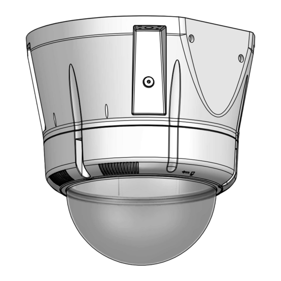
SM75C12N
Vandal-Resistant Surface Mount Dome Housing
Installation and Operation Instructions for the following models:
SM75C2N
IP Network Ready, vandal resistant outdoor surface mount housing
that can be mount facing down or facing rowards the sky.
Clear dome, with 12VDC input, heater/blower, for an IPNetwork
PTZ camera.
Before attempting to connect or operate this product,
please read these instructions completely.
© 2009, Videolarm, Inc. All Rights Reserved
www.videolarm.com
CERTIFIED
81-IN5421
01-30-2009
Advertisement
Table of Contents

Subscribe to Our Youtube Channel
Related Manuals for Moog Videolarm SM75C12N


Summary of Contents for Moog Videolarm SM75C12N
- Page 1 © 2009, Videolarm, Inc. All Rights Reserved SM75C12N © 2009, Videolarm, Inc. All Rights Reserved Vandal-Resistant Surface Mount Dome Housing www.videolarm.com Installation and Operation Instructions for the following models: SM75C2N IP Network Ready, vandal resistant outdoor surface mount housing that can be mount facing down or facing rowards the sky.
- Page 2 IMPORTANT SAFEGUARDS SAFETY PRECAUTIONS Read these instructions. Keep these instructions. CAUTION Heed all warnings RISK OF ELECTRIC SHOCK DO NOT OPEN Follow all instructions. Do not use this apparatus near water. CAUTION: TO REDUCE THE RISK OF Clean only with damp cloth. ELECTRIC SHOCK, DO NOT REMOVE Do not block any of the ventilation openings.
- Page 3 LIMITED WARRANTY FOR VIDEOLARM INC. PRODUCTS VIDEOLARM INC. warrants this Product to be free from defects in material or workmanship,as follows: PRODUCTCATEGORY PARTS LABOR All Enclosures and Electronics Five (5) Years Five (5) Years Pan/Tilts Three (3) Years **6 months if used in autoscan Three (3) Years **6 months if used in autoscan /tour operation /tour operation...
-
Page 4: Electrical Specifications
Contents of Box Electrical Specifications SM75C12N Power 12VDC Class 2 Only 12 VDC 3.3 Amps Total Power: 47 Watts Accessories: Heater: 20 Watts/Blower: 2 Watts Camera Power: 25 Watts Max English Tools Required: .100” Flat Head Screwdriver Phillips Head Screwdriver 12VDC 3.3 amperios... - Page 5 Wall Wall Mounting Mounting WALL Use teflon tape WALL MOUNT Mount only to suitable material such as brick, Use Teflon Tape (included) to seal conduit plugs. concrete, wood, etc. (Wall mount sold separately) • Monte solamente al material conveniente tal como ladrillo, •...
- Page 6 Surface Surface Mounting Mounting Remove the (4) side plates . Mounting Surface Securely mount housing to mounting surface. Replace should be of suitable material such as brick, side plates when complete. concrete, wood etc. • Con seguridad montaje que contiene a la superficie de •...
- Page 7 POWER Power and Control Inputs (Outside of Housing) RJ45 Camera Power (+ 12 VDC) 24VAC Camera Power (- 12 VDC) POWER Orange RJ45 Camera Max 40 Watts Accessory Power (+12 VDC) Yellow Camera Orange Heater/Blower Yellow Accessory Power (-12 VDC) Green (Large) 52 Watts...
- Page 8 Use the rubber seal when mounting housing Pull the seal over the face of the dome and up right. Center the seal over the dome. down onto the housing. • Utilice el sello de goma al montar contener encima de la •...
-
Page 9: Axis 214
Axis 214 Mounting Hole 3026 Mounting (3) #8 x 3/8” Plate Captive 2" Screw Mounting Mounting Hole Hole Install the camera to the mounting plate using (3) 3mm x 12mm bolts and lock washers. Place (3) #8x3/8” screws on the spacers and line up the mounting slots. Slide plate in and secure. •... - Page 10 Axis 215 (3) #8x3/8” 1" Captive Screw 1" MOUNTING HOLE MOUNTING HOLE 2" AXIS215-VL3026 Install the camera to the mounting plate with (4) #8 screws and lock washers provided. Place (3) #8x3/8” screws on the spacers and align the mounting slots. Slide on plate and camera then secure. •...
- Page 11 Locking Screw Captive (3) #8 x 3/8” Screw Locking Keyhole Pins Slot (3) ½" Position locking pins and locking screw over slots and turn clockwise; secure the screw. Place (3) #8x3/8” screws on the spacers and line up mounting slots. Slide on plate and camera then secure. •...
- Page 12 Open Screw Slots Cable Ties POWER Camera Power (24VAC) Camera Power (24VAC) Orange CONTROL RJ45 Ethernet Connector ALARMS Alarm 1 Blue Alarm 2 Violet Alarm 3 Gray Captive Common White Screw Complete the wiring to camera. Attach the camera assembly to the housing by sliding the (3) This is what the typical path of illumination will look like with the setting at 30 degrees.
- Page 13 Canon VB-C50IR ½" 2539 Mounting Plate Mounting Captive Hole Screw 1" 2" Mounting Hole Mount the camera to the 2539 plate using the provided hardware. Place (3) 8 x 32 x 3/8 Phillips head screws on the top of the spacer as shown above. Slide plate in and secure. •...
-
Page 14: Elmo Ptc-200C
Elmo PTC-200C Captive (3) 8 x 32 x 3/8 Screw 2539 Mounting Plate ½" Mounting Hole 1" 2" Mounting Hole Place the camera onto the quick release bracket using the (4) metric 3M Phillips head screws provided. Place the screws on the spacers. Slide on the plate and camera then secure. •... -
Page 15: Elmo Ptc-400C
Elmo PTC-400C ½" 2539 Mounting Plate Mounting Hole Quick release plate 1" 2" Mounting Hole Attach quick release bracket to mounting plate using (4) #8 screws and star washer. Complete assembly as shown, then secure camera to the quick release plate. •... - Page 16 JVC VN-C30U 2539 Mounting Plate ½" 2" Mounting Hole Remove the camera plate and mount to the bracket using the (3) metric 3M Phillips head screws. Reattach plate back to the camera. Place the screws on the spacers. Secure the plate and camera. •...
- Page 17 JVC VN-C655U ½" 1" Mounting 2630 Mounting Hole Plate Place the camera on the bracket with the (4) phillips head screws. Use (4) 1” spacers and (4) 1/2” spacers provided. Place the screws on the spacers. Slide on the plate and camera then secure. •...
-
Page 18: Sony Sncrz25
Pixord 261/262 ½" Mounting 2630 Mounting Hole Plate Install camera to the bracket with (3) 8x32x.5” flat head screws, nuts and washers. Place (3) 8x32x3/8”screws on the spacers. Slide on the plate and camera then secure. • Instale la cámara fotográfica al soporte con (3) los tornillos, las tuercas y las arandelas principales el 8x32x.5"planos. Coloque (3) 8x32x3/8"screws en los espaciadores. -
Page 19: Sony Sncrz30
Sony SNCRZ30 2" 2539 Mounting Mounting Hole Plate Attach bracket with (1) 1/4x20 bolt, washer and lock washer. Place (3) 8x32x3/8”screws on the spacers. Slide on the plate and camera then secure. • Una el soporte con (1) el perno 1/4x20, la arandela y la arandela de cerradura. Coloque (3) 8x32x3/8" screws en los espaciadores. -
Page 20: Toshiba Ik-Wb21A
Toshiba IK-WB21A Mounting Hole 1" 2" 2539 Mounting Mounting Hole Plate Remove camera bracket and attach to the 2539 plate with (4) 8x32x3/8 bolts and star washers. Place (3) 8x32x3/8”screws on the spacers. Slide on the plate and camera then secure. •... -
Page 21: Replacement Parts List
Replacement Parts List SM75C12N Wall Mount WMSM7 Sold Separately Be sure the bracket is properly and securely mounted to a supporting structure capable of rigidly holding the weight of the entire unit. Part Number Description RPSM7501 DOME SEAL RPRH7502 LOWER TRIM RING... -
Page 22: Product Registration/Warranty
Product Registration/Warranty Thank you for choosing Videolarm. We value your patronage and are solely committed to providing you with only the highest quality products available with unmatched customer service levels that are second-to-none in the security industry. Should a problem arise, rest assure that Videolarm stands behind its products by offering some of the most impressive warranty plans available: 3 Years on all Housings, Poles, Power Supplies, and Accessories and 5 Years on all camera systems (SView, QView, Warriors), and InfraRed Illuminators.
Need help?
Do you have a question about the SM75C12N and is the answer not in the manual?
Questions and answers