Table of Contents
Advertisement
Quick Links
Download this manual
See also:
Installation Manual
Advertisement
Table of Contents

Related Manuals for Ganz ZN-DNT352XE


Summary of Contents for Ganz ZN-DNT352XE
- Page 2 ZN-DNT352XE Installation Guide INFORMATION TO USER CAUTION RISK OF ELECTRIC SHOCK, DO NOT OPEN CAUTION: TO REDUCE THE RISK OF ELECTRIC SHOCK, DO NOT REMOVE COVER (OR BACK). NO USER SERVICEABLE PARTS INSIDE. REFER SERVICING TO QUALIFIED SEERIVCE PERSONEL. This symbol is intended to alert the user to the presence of un-insulated “dangerous voltage”...
-
Page 3: Table Of Contents
ZN-DNT352XE Installation Guide Table of Contents 1. FEATURES ......................... 4 2. PACKAGE CONTENTS ....................5 3. PART NAMES ......................6 4. INSTALLATION ......................7 4.1. Installation Template ...................... 8 4.2. Setting the Lens Position ....................9 4.3. Setting the Image Attribute .................... 9 5. -
Page 4: Features
ZN-DNT352XE Installation Guide 1. FEATURES Camera Full HD outdoor dome IP camera (Vandal proof) High quality compression in real time streaming 1/2.7” High Quality CMOS Image Sensor True Day / Night (ICR) and WDR Improvement of color rolling suppression Streaming ... -
Page 5: Package Contents
ZN-DNT352XE Installation Guide 2. PACKAGE CONTENTS Unpack carefully and handle the equipment with care. The packaging contains: Camera DC power adaptor DC Jack Cable 9-pin and 2-pin terminal block Video out cable Screws and anchors Installation template Hex wrench driver... -
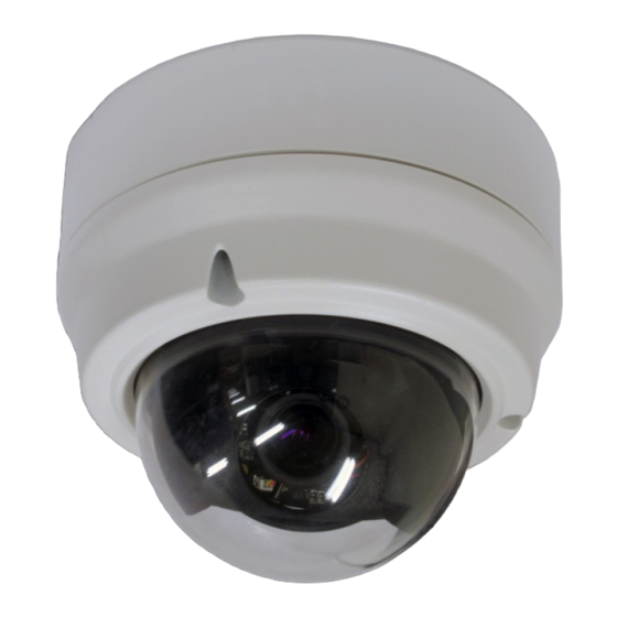
Page 6: Part Names
ZN-DNT352XE Installation Guide 3. PART NAMES * Models herein and their appearance are subject to change without any prior notice. ① Fan The fan and heater (underneath the black panel) are implemented for controlling temperature and mois ture of the internal device. -
Page 7: Installation
ZN-DNT352XE Installation Guide 4. INSTALLATION Place the installation template that is provided in the package on the desired position of installation. Attach the waterproof silicon band on the bottom plate of the device. Drill three holes on the template and insert anchor blocks into the holes. -
Page 8: Installation Template
ZN-DNT352XE Installation Guide The camera may fall off the ceiling even after the proper installation and mounting. To prevent any accident, make sure the ceiling is firm and stable Caution enough to support the camera. If any reinforcement is needed, consult with your safety personnel and proceed with the installation. -
Page 9: Setting The Lens Position
ZN-DNT352XE Installation Guide 4.2. Setting the Lens Position Set the lens position and adjust the zoom and focus by performing procedures as below. 1) Remove the dome cover. 2) Adjust the lens to the desired position by manually moving its body in the following directions. -
Page 10: Connections
ZN-DNT352XE Installation Guide 5. CONNECTIONS N / A N / A N / A N / A VIDEO AUDIO DC12V ETHERNET MICRO SD N / A N / A ① Audio input/output The camera has a mono audio input and a mono audio output. Since the output power for the... - Page 11 ZN-DNT352XE Installation Guide Do not exceed the maximum input voltage or relay rate. Caution Internal Internal Output of Output of Sensor Sensor Relay Type Voltage Type ④ Alarm (DO) connection Only the relay type is supported. Relay Rating: Max 24VAC 500mA or 12VDC 1A Do not exceed the maximum relay rating.
- Page 12 ZN-DNT352XE Installation Guide ⑤ LAN connection This is a RJ45 LAN connector for 10/100 Base-T Ethernet. Connect a LAN cable. LED1 LED2 This LED lights up as orange and turns green when the encoder is powered on. ⑥ 12V DC Power A 12 DC power connector is required for this device.
-
Page 13: Configuration
ZN-DNT352XE Installation Guide 6. CONFIGURATION 6.1.Set up network environment The default IP address of your IP device is 192.168.XXX.XXX. You can find the available IP address from the MAC address of your device. Please make sure the device and your PC are on the same network segment before running the installation. -
Page 14: View Video Using Ipadmin Tool
ZN-DNT352XE Installation Guide 6.2.1. View video using IPAdmin Tool IPAdminTool automatically searches all activated network encoders and IP cameras and shows the product name, IP address, MAC address and etc. IPAdminTool is provided with SDK at the following SDK path. -
Page 15: View Video Using Ip Address
ZN-DNT352XE Installation Guide 7. When the dialog box appears to request user name and password, enter the default value for the administrator account (case-sensitive) as below: ID: root Password: pass 8. Refresh the page and check if the live image is displayed successfully. -
Page 16: Appendix (A): Specifications
ZN-DNT352XE Installation Guide APPENDIX (A): SPECIFICATIONS Summary Camera Module Image Sensor 1/2.7” 1080p CMOS CMOS Effective Pixels 1920x1080 Scanning system Progressive scanning Resolution 1920 x 1080 Min. Color: 1.0 lux, F1.2 ELECTRICAL Illumination BW: 0.001 lux, F1.2 AGC Control Auto Lens 3.0~9.0mm Vari-Focal F1.2... -
Page 17: Electrical Characteristics
ZN-DNT352XE Installation Guide Electrical Characteristics Power Source DC 12V / PoE IEEE802.3af (Class 0) Power Consumption 1100mA (Heater On) Video Output 1 Vp-p, 75Ω, Composite Audio Input Linein, 1.43Vp-p(Min 1.35Vp-p, max 1.49 Vp-p), 39 KΩ Audio Output Lineout, 46mW Power, 16 Ω... -
Page 18: Appendix (B): Power Over Ethernet
ZN-DNT352XE Installation Guide APPENDIX (B): POWER OVER ETHERNET The Power over Ethernet (PoE) is designed to extract power from a conventional twisted pair Category 5 Ethernet cable, conforming to the IEEE 802.3af Power-over-Ethernet (PoE) standard. IEEE 802.3af allows for two power options for Category 5 cables. -
Page 19: Appendix (C): Dimensions
ZN-DNT352XE Installation Guide APPENDIX (C): DIMENSIONS (Unit: mm) 01A.01... -
Page 20: Appendix (D): Hexadecimal-Decimal Conversion Table
ZN-DNT352XE Installation Guide APPENDIX (D): HEXADECIMAL-DECIMAL CONVERSION TABLE Refer to the following table when you convert the MAC address of your device to IP address. Hex Dec Hex Dec Hex Dec Hex Dec Hex Dec Hex Dec Hex Dec 94 148... -
Page 21: Revision History
ZN-DNT352XE Installation Guide REVISION HISTORY MAN# DATE(M/D/Y) Comments 01A.01 05/02/2012 First release version 01A.01...
Need help?
Do you have a question about the ZN-DNT352XE and is the answer not in the manual?
Questions and answers