Nibe SMO 10 Installation And Maintenance Instructions Manual
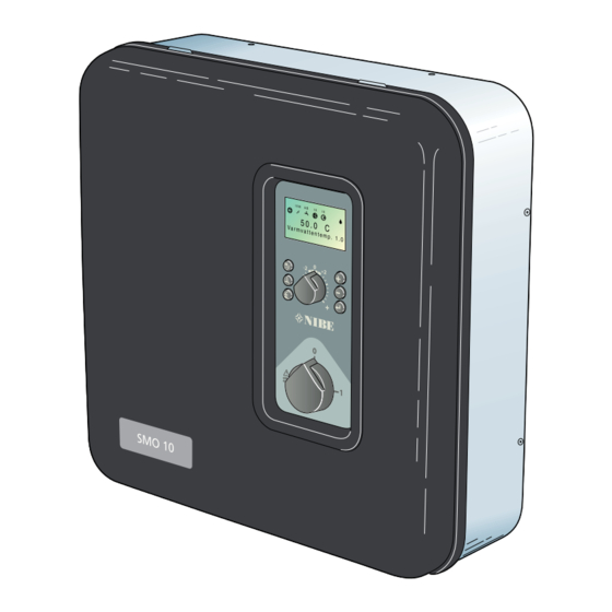
Control module designed to optimally control up to nine nibe outdoor air pumps together with other heating equipment.
Hide thumbs
Also See for SMO 10:
- Service instruction (8 pages) ,
- Installation and maintenance instructions manual (60 pages)
Table of Contents
Advertisement
Advertisement
Table of Contents

Related Manuals for Nibe SMO 10


Summary of Contents for Nibe SMO 10
- Page 1 MOS GB 0923-4 INSTALLATION AND MAINTENANCE INSTRUCTIONS SMO 10 NIBE SMO 10 511882...
-
Page 3: Table Of Contents
Dealing with malfunctions Electrical connections Low temperature or a lack of hot water __________________ 8 Screened 3 core cable between SMO 10 The hot water temperature does not reach the desired level and a heat pump ___________________________________ 33 for ”Extra hot water” _________________________________ 8... - Page 4 General General In order to get the ultimate benefit from your NIBE SMO 10 you should read th- rough these Installation and Maintenance Instructions. SMO 10 is a control module designed to optimally control up to nine NIBE outdoor air pumps together with other heating equipment.
-
Page 5: General
Expansion vessel with necessary safety equipment hot water equipment, creates a complete installation. Flow line sensor 1 SMO 10 can be used for with several different connection Flow line sensor 2 options. The base is the NIBE air/water heat pump, which, Auxiliary relay in turn, can be docked on to electric boilers, oil-fired boil-... -
Page 6: Front Panel
Power stage III is connected. “Hot water temp” is normally shown. Only flashes when hot water is being heated by the Fourth row: Shows the information symbols. electrical addition. Menu number. Pool charging in progress. Key lock activated. NIBE SMO 10... -
Page 7: Switch
The different operating modes are: Offset heating curve Auto mode: SMO 10 automatically selects the op- This knob is used to change the heating curve's par- erating mode with reference to the outdoor temper- allel offset and in doing so the room temperature. -
Page 8: Room Temperature
One to three lines approximately repre- sents a one degree change in room temperature. NOTE! An increase in the room temperature may be in- hibited by the radiator or floor heating thermostats, if so these must be turned up. NIBE SMO 10... -
Page 9: Setting With Diagrams
User guide Room temperature Setting with diagrams Shifting the heating curve -2 The heating control system on the SMO 10 is controlled by HEATING CURVE the outside temperature. This means the flow temperature VÄRMEKURVA is regulated in relation to the current outdoor temperature. -
Page 10: Dealing With Malfunctions
10 °C above the set value in menu 9.1.14. Max power output, knob (101) or fuse rating, knob (100), is set too low. High hot water temperature Mixer valve set too high. Incorrectly set values for hot water production. NIBE SMO 10... -
Page 11: Switch Position
Terminals 3, 8, 9, 14, 18, 20 and 26 on the terminal block (11) are always powered. NOTE! As SMO 10 can be connected to a large number of external units, these should also be checked. NIBE SMO 10... -
Page 12: Alarm Indications On The Display
Error text is displayed when contact between SMO 10 and This information is shown when the low pressure pres- sostat in the air/water heat pump has tripped. SMO 10 the air/water heat pump is lost. SMO 10 switches to ad- ditional power*. switches to additional power*. -
Page 13: Resetting The Miniature Circuit Breakers
The miniature circuit breaker (7) is located above the circuit D E F R O S T I N G T I M E board on the right hand side under the cover of SMO 10. 1 . 0 Normal mode of the miniature circuit breakers is ”1” (to the left). -
Page 14: General Information For The Installer
General information for the installer Suspension Docking SMO 10 is attached to a wall using four screws. There are The safety equipment must be installed in accordance with two holes on the reverse for hanging SMO 10 and two current regulations for all docking options. See www.nibe. -
Page 15: Connection
Installation / Adjustment General information for the installer Connection SMO 10 must be installed via an isolator switch with a mi- nimum breaking gap of 3 mm. NOTE! Disconnect the control module before insulation testing To prevent interference, sensor cables and the house wiring. -
Page 16: Docking - Hot Water Heating
(VVG). cable when cable routing. In cases where the additional heater is located after the three way valve, the hot water is heated by the hot water heater’s immersion heater when additional heat is acti- vated. NIBE SMO 10... -
Page 17: Connecting Hot Water Heating
Menu 9.3.15 Block HW/Heating Deselection can be made here if there is no hot wa- ter or heating demand. The options are “No hot water”, “No heating” or “HW+heating”. Factory setting “HW+heating”. NIBE SMO 10... -
Page 18: Docking - Oil Addition
Installation / Adjustment Docking – Oil addition Docking – Oil addition NIBE air/water heat pump docked to the oil-fired/pellet boiler together with SMO 10 and water heater (floating condensing) SMO 10 FG1* UKV* SÄV VXV1 NIBE air/water heat pump Function SMO 10 controls air/water heat pump, oil-fired boiler,... -
Page 19: Connection Oil Addition
The value can be set between 10 and 65 °C. The fac- tory setting is 55°C. Menu 9.2.10 Oil b. min. time Number of hours the oil boiler is to be active. The value can be set between 1 and 12 hours. The factory setting is 2 hours. NIBE SMO 10... -
Page 20: Docking - Immersion Heater After Three Way Valve
Docking – Immersion heater after three way valve Docking – Immersion heater after three way valve NIBE air/water heat pump docked to the immersion heater after the three way valve together with SMO 10 and water heater (floating condensing) SMO 10... -
Page 21: Connecting Immersion Heater After Three Way Valve
Safety equip- ment can consist of temperature limiter, isolator and relevant by-pass. SMO 10 produces a control voltage of 230 V for output control. The various stages of the immersion heater are controlled by relays TS1, TS2 and TS3. -
Page 22: Docking - Exhaust Air Heat Pump
Installation / Adjustment Docking – Exhaust air heat pump Docking – Exhaust air heat pump NIBE air/water heat pump and NIBE exhaust air heat pump controlled by SMO 10 SMO 10 NIBE air/water heat pump FIGHTER 2010 LP 1 Function... -
Page 23: Connecting The Exhaust Air Heat Pump
Quick guide – menu settings when dock- The shunt motor (19) in the exhaust air heat pump must ing to exhaust air heat pump be controlled by SMO 10. See corresponding Installation Menu 9.2.1 Start add. heat. and maintenance instructions for the shunt motor’s posi- The degree minute deficit that must be set before... -
Page 24: Docking - Pool Heating
Installation / Adjustment Docking – Pool heating Docking – Pool heating NIBE air/water heat pump connected for pool heating together with oil fired boiler and SMO 10 and water hea- ter (floating condensing) SMO 10 FG1* UKV* VXV 2 Pool... -
Page 25: Pool Heating Connection
0.5 °C. The factory setting is 25 °C. Menu 8.4.4 Pool stop temp. The temperature at which pool heating is to stop. The value can be adjusted between 5 and 40 °C in increments of 0.5 °C. The factory setting is 28 °C. NIBE SMO 10... -
Page 26: Docking - Gas Boiler
Docking – Gas boiler Docking – Gas boiler NIBE air/water heat pump docked to the gas boiler before the three way valve together with SMO 10 and water heater (floating condensing) The gas boiler can also be connected after the three way valve together with a shunt valve. Connection option “Docking”... -
Page 27: Connecting A Gas Boiler
SMO 10 produces a control voltage of 230 V for output control. The various stages of the gas boiler are controlled by relays TS1, TS2 and TS3. In cases where the gas boiler only has one stage, it must be connected to TS2, and knob (102) must be set to position ”A”. -
Page 28: Docking - Several Heat Pumps
Installation / Adjustment Docking – Several heat pumps Docking – Several heat pumps Several heat pumps together with SMO 10 and water heater (floating condensing) SMO 10 FG1* UKV* SÄV NIBE air/water heat pump HP2 SÄV SÄV NIBE air/water heat pump HP1... -
Page 29: Connecting Several Heat Pumps
Select the required address number In the heat pump. This Is done In channel 20 In the FIGHTER 2005/2010 and SMO 10 can control up to 9 NIBE air/water heat pumps, of channel A1 on FIGHTER 2020. Confirm with the enter but- which, max one for hot water. -
Page 30: Docking - Extra Shunt Group
Installation / Adjustment Docking – Extra shunt group Docking – Extra shunt group NIBE air/water heat pump and SMO 10 with two heating circuits SMO 10 SV2 CP2 UKV* Function A shunt valve (SV2) a circulation pump (CP2) can be con-... -
Page 31: Connecting Extra Shunt Group
(230 V closing signal), 32 (N) and 31 (230 V opening sig- nal) on terminal block (11). Menu 3.3 Min. supply temp. 2 Note that SMO 10 produces 230 V control signals for con- The desired minimum level for the supply tempera- trol of external contacts. -
Page 32: Function Description - Heating
Room sensor operating mode in the status field. A further press switch- A room sensor, type RG 05, can be connected to SMO 10 es to the next step. between pos 3 and 4 on terminal block X4 on the EBV Press the enter button to return to normal view. -
Page 33: Quick Guide - Menu Settings Heating
The calculated flow temperature never exceeds the set level irrespective of the outdoor temperature, curve slope or offset heating curve. The value can be set between 10 and 80 °C. The factory setting is 55°C. NIBE SMO 10... -
Page 34: Function Description - Extra Hot Water
The factory setting is 14 days. External activation of “Extra hot water” Menu 1.5 Next XHW action An external contact function can be connected to SMO 10 Future increases to the “Extra hot water” level are for activation of the “Temporary extra hot water” func- shown here. -
Page 35: Electrical Connections
Communication cable between SMO 10 and a heat pump A screened 3 core cable Is used for communication bet- ween SMO 10 and a NIBE air/water heat pump. NOTE! Connect terminal 61 on terminal block (11) in SMO to Communication cables must be separated... -
Page 36: Connecting The Outside Sensor
The return sensor (RG1) must be installed on the return line from the heating system. Position the sensor according to the relevant outline diagram under section “Docking”. The sensor must be connected to terminals 45 - 46 on the terminal block (11). NIBE SMO 10... -
Page 37: Load Monitor
Electrical connections Load monitor Tariff SMO 10 is equipped with an internal load monitor. For Where centralised load control or tariff control is used this the load monitor to function effectively the accompanying can be connected to the terminal block (14) on the EBV current transformers must be connected. -
Page 38: Terminal Diagram
Installation / Adjustment Electrical connections Terminal diagram * The interference protection that is supplied in the enclosed kit must be installed either on terminal block 11 or on the contactor. NIBE SMO 10... - Page 39 Installation / Adjustment Electrical connections NOTE! To prevent interference, sensor cables and communication cables must be separated (min 20 cm) from high voltage cable when cable routing. NIBE SMO 10...
-
Page 40: Starting
SMO 10 is connected. 9.3.10, Operating mode: Displays SMO 10’s operating 2. Set the switch (8) to 1. SMO 10 must be powered mode. within 5 minutes after the heat pump has been started, 5.2, VP operating status: Shows heat pump’s operating to prevent triggering a communication alarm. -
Page 41: Menu Management
Ensure the operating mode is not changed I II III during quick movement 5 0 . 0 ° C H o t w a t e r t e m p . 13.43 Menu name Clock Menu number Key lock NIBE SMO 10... -
Page 42: Menu Tree
Normal, covers the normal user's needs. Extended, shows all menus except the serv- ice menus. Service, shows all menus, returns to nor- mal 30 minutes after the last button was * Requires accessory and activation in menu 9.3.3. pressed. NIBE SMO 10... - Page 43 5.11 Suction gas temp # 5.12 Liquid temperature # 5.13 Hotgas temperature # 5.14 Return temperature # 5.15 Diff. Supply/return # 5.16 Start defrosting # 5.17 Return to 5.0 * Requires accessory and activation in menu 9.3.5. NIBE SMO 10...
-
Page 44: Menu Tree
7.5.3 8.3.7 Heat system 8.5.0 8.5.1 Return to 8.3.0 Period settings Period time 7.5.4 Offset heating curve 8.5.2 Return to 8.0 Max time for HW 7.5.5 HW deactivated 8.5.3 Return to 8.5.0 7.5.6 Pool deactivated 7.5.7 Return NIBE SMO 10... -
Page 45: Menu Tree
9.3.15.0 9.3.15.1 BW-Zirkulation Time der Period BWUP 9.3.16 9.3.15.2 Block HW/Heating Period time BW-UP 9.3.17 9.3.15.3 Heat drop at alarm Acc. run time BW-UP 9.3.18 9.3.15.3 Type of HW sensor Return to 9.3.15.0 9.3.19 Return to 9.3.0 NIBE SMO 10... -
Page 46: Menu Explanation
NOTE! These settings should only be Extended, shows all menus except the serv- made by persons with the necessary expertise. ice menus. Service, shows all menus, returns to nor- mal 30 minutes after the last button was pressed. * Accessories are needed. NIBE SMO 10... -
Page 47: 1.0 Hot Water Temp
Menu 1.5 Next XHW action Future increases to the “Extra hot water” level are shown here. Menu 1.6 HW run time How long hot water heating has been in progress is shown here (accumulated). Menu 1.7 Return Return to menu 1.0. NIBE SMO 10... -
Page 48: Supply Temp
Current value for number of degree-minutes. This value can be changed to speed up the start of heating produc- tion. The value can be set from 100 and downwards. The fac- tory setting is 0. Menu 2.9 Return Return to menu 2.0. NIBE SMO 10... -
Page 49: Supply Temp. 2
The current actual return line temperature from heating The value can be set between -10 and +10. The factory system 2 is displayed here. setting is 0 °C. Menu 3.8 Return Return to menu 3.0. * Requires accessory and activation in menu 9.3.3. NIBE SMO 10... -
Page 50: 4.0 Outdoor Temp
2 in the air/water heat pump is shown Manual activation of defrosting procedure in the air/water here. heat pump. FIGHTER 2005/2025: The accumulated number of starts with the compressor in the heat pump is shown here. Menu 5.17 Return Return to menu 5.0. NIBE SMO 10... -
Page 51: 6.0 Room Temperature
Equal values or the stop time before the start time mean that extra hot water is not activated. Menu 7.4.8 Return Return to menu 7.4.0 * Requires accessory and activation in menu 9.3.5. NIBE SMO 10... -
Page 52: Other Adjustments
Here you can select wether pool heating shall be turned off ting is 25 °C. during the vacation set back. Can be set to ”Yes” or ”No”. The factory setting is ”Yes”. 7.5.7 Return Return to menu 7.5.0. Menu 7.6 Return Return to menu 7.0. NIBE SMO 10... - Page 53 Pool settings are made on the sub-menus to this menu. Menu 8.5.3 Return to menu 8.5.0. Menu 8.4.1 Pool control You choose here whether pool control should be On or Menu 8.6 Return Off. Return to menu 8.0. NIBE SMO 10...
-
Page 54: Heat Pump Settings
If the compressor does not manage to obtain the tempera- ture after this time, SMO 10 switches to combined mode The value can be set between 10 and 40 °C. The factory and the immersion heater starts in the hot water heater. -
Page 55: Add. Heat Settings
Control Menu explanation 9.2.0 Add. heat settings Settings regarding additional heat and shunt in SMO 10 Menu 9.2.8 Oil burner temp. and any extra shunt can be made on the sub-menus in this The oil boiler’s temperature is shown in °C here. -
Page 56: Operating Settings
Selection of the flow temperature in period 2. The value is Menu 9.3.9 Factory setting adjustable between 15 and 50 °C. Factory setting is 40 °C. Return to the factory settings in SMO 10, “Yes” or “No”. Menu 9.3.11.6 Return Return to menu 9.3.11.0. - Page 57 3 °C. If ”No” is selected, the supply temperature does not drop in the event of an alarm. This means that SMO 10 must be Meny 9.3.15.0 BW-Zirkulation checked regularly. If an earlier alarm indication is required, e.g.
-
Page 58: Quick Start
Menu 9.5.1 – 9.5.10 Log 01 – 10 Shows the last 10 alarms. Menu 9.5.11 Return Return to menu 9.5.0 9.6.0 System Info Only for service personnel. Menu 9.7 Return Return to menu 9.0. NIBE SMO 10... -
Page 59: Technical Specifications
Miscellaneous Technical specifications Technical specifications Dimensions and setting-out coordinates 151.5 Ø 6 38,1 NIBE SMO 10... -
Page 60: Component Locations
Miscellaneous Technical specifications Component locations I II III I II 5 0 . 0 C V a r m v a t t e n t e m p e r a t u r 13.43 NIBE SMO 10... -
Page 61: List Of Components
4,31 21,93 4,12 16,62 3,90 12,71 3,65 9,81 3,38 7,62 3,09 5,97 2,80 4,71 2,50 3,75 2,22 3,00 1,95 2,42 1,70 1,96 1,47 1,60 1,27 1,31 1,09 1,08 0,94 0,83 0,76 0,69 0,65 0,56 0,54 0,46 0,46 NIBE SMO 10... -
Page 62: Electrical Circuit Diagram
Miscellaneous Technical specifications Electrical circuit diagram NIBE SMO 10... - Page 63 Miscellaneous Technical specifications NIBE SMO 10...
-
Page 64: Accessories
Miscellaneous Technical specifications NIBE SMO 10... -
Page 65: Enclosed Kit
Miscellaneous NIBE SMO 10... - Page 66 HL 65, Part no. 089 883 EP 42 EP 26 °C °C LE K Immersion heater Immersion heater Electric boiler Electric boiler Low temperature boiler for oil and gas 13 kW 15 kW 26 kW 42 kW NIBE SMO 10...
- Page 67 Max number of air/water heat pumps Max number of sensors 14 x Max number of charge pumps Max number of circulation pumps (heating sys- tem) Supply voltage 230 V 50 Hz Max. current 2,5 A Enclosure class IP21 NIBE SMO 10...
- Page 68 NIBE SMO 10...
- Page 72 Druzstevni zavody Drazice s.r.o, Drazice 69, CZ - 294 71 Benatky nad Jizerou Tel: +420 326 373 801 Fax: +420 326 373 803 E-mail: nibe@nibe.cz www.nibe.cz NIBE Syste technik G bH, Am Reiherpfahl 3, 29223 Celle Tel: 05141/7546-0 Fax: 05141/7546-99 E-mail: info@nibe.de www.nibe.de Vølund Var eteknik, Filial af NIBE AB, Brogårdsvej 7, 6920 Videbæk...
Need help?
Do you have a question about the SMO 10 and is the answer not in the manual?
Questions and answers