Table of Contents
Advertisement
Advertisement
Table of Contents

Related Manuals for Nibe AXC 50


Summary of Contents for Nibe AXC 50
- Page 1 Installer manual AXC 50 Accessories IHB GB 1222-1 231158...
-
Page 3: Table Of Contents
Electrical circuit diagram Pipe connections 10 Passive/active cooling (2-pipe) Outline diagram Electrical connection General Program settings Pipe connections Electrical circuit diagram Outline diagram Electrical connection 6 Hot water comfort Program settings General Electrical circuit diagram AXC 50 Table of Contents |... -
Page 4: General
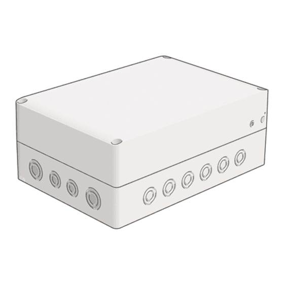
1 General This accessory is used to enable connection and control Component positions of (a AXC 50 is required for each of the following access- ory functions that is used): Shunt controlled additional heat Step controlled additional heat Passive cooling (4-pipe) -
Page 5: Common Electrical Connection
1 2 3 4 The heat pump must not be powered when in- stalling AXC 50. Electrical circuit diagrams are at the end of the chapter for each connection option. Connecting the supply Connect the power supply to terminal block X1 as illus- trated. -
Page 6: Shunt Controlled Additional Heat
Shunt valve The heat pump controls a shunt valve and a circulation pump via AXC 50. If the heat pump cannot maintain the The shunt valve (QN11) is located on the flow line to the right flow temperature the additional heating starts. -
Page 7: Outline Diagram
Connection, filling brine External additional heat Accessory card (AXC 50) Designations according to standards 81346-1 and 81346- BT52 Temperature sensor, boiler Expansion vessel, closed Outline diagram F1345 with AXC 50 and external addition -EM1 -FL10 -KA1 -EM1-AA5 -CM5 -BT52 -EM1... -
Page 8: Electrical Connection
(230 V, open), AA5-X9:5 (N) and AA5-X9:4 (230 V, close). F1345 must not be powered when installing AXC 50. Connection of sensors and external blocking Use cable type LiYY, EKKX or similar. -
Page 9: Program Settings
The DIP switch on the accessory card must be set as fol- lows. -X10 Program settings Program setting of AXC 50 can be performed via the start guide or directly in the menu system. Start guide The start guide appears upon first start-up after heat pump installation, but is also found in menu 5.7. -
Page 10: Electrical Circuit Diagram
Electrical circuit diagram Chapter 3 | Shunt controlled additional heat AXC 50... -
Page 11: Step Controlled Additional Heat
4 Step controlled additional heat General Pipe connections With AXC 50 a further three potential free relays are used The extra circulation pump (GP10) is positioned according for addition control, which then gives max 3+3 linear or to the outline diagram. -
Page 12: Outline Diagram
FL11 - FL12 Safety valve, collector side FL13 - FL14 Safety valve, heating medium side Designations according to standards 81346-1 and 81346- HQ12 - HQ15 Particle filter Outline diagram F1345 with AXC 50 and external addition -EB1 -EB1-AA5 -FL10 -CM5 -EB1 -CP20... -
Page 13: Electrical Connection
Connect step 2 to AA5-X9:3 and 4. F1345 must not be powered when installing AXC 50. Connect step 3 to AA5-X9:5 and 6. Connecting external blocking Use cable type LiYY, EKKX or similar. -
Page 14: Program Settings
Program settings Program setting of AXC 50 can be performed via the start guide or directly in the menu system. Start guide The start guide appears upon first start-up after heat pump installation, but is also found in menu 5.7. -
Page 15: Electrical Circuit Diagram
Electrical circuit diagram AXC 50 Chapter 4 | Step controlled additional heat... -
Page 16: Extra Climate System
Install the temperature sensors with cable ties with the heat conducting paste and aluminium tape. Then insulate with supplied insulation tape. NOTE Sensor and communication cables must not be placed near power cables. Chapter 5 | Extra climate system AXC 50... -
Page 17: Outline Diagram
Reversing valve, heating/hot water XL27 - Connection, filling brine RM10 - Non-return valve XL28 RM13 EP21 Climate system 2 Designations in component locations according to Accessory card (AXC 50) standard IEC 81346-1 and 81346-2. AXC 50 Chapter 5 | Extra climate system... - Page 18 Outline diagram F1345 with AXC 50 and up to three extra climate systems -EP23 -AA5 -BT2 -GP20 -BT3 -QN25 -EP22 -AA5 -BT2 -GP20 -BT3 -QN25 -EP21 -AA5 -BT2 -GP20 -BT3 -EB1 -QN25 -FL10 -CM5 -EB1 -CP20 -EB100-BT25 -GP10 -GP18 -QM42...
-
Page 19: Electrical Connection
Electrical installation and wiring must be carried out in accordance with the stipulations in force. F1345 must not be powered when installing AXC 50. Connection of the mixing valve motor (QN25) Connection of sensors and external adjust- Connect the mixing valve motor (QN25) to AA5-X9:6 ment (230 V, open), AA5-X9:5 (N) and AA5-X9:4 (230 V, close). -
Page 20: Program Settings
Also see the Installer manual for relevant heat pump/indoor module. Program settings Program setting of AXC 50 can be performed via the start guide or directly in the menu system. Start guide The start guide appears upon first start-up after heat pump/indoor module installation, but is also found in menu 5.7. -
Page 21: Electrical Circuit Diagram
Electrical circuit diagram AXC 50 Chapter 5 | Extra climate system... -
Page 22: Hot Water Comfort
Install the temperature sensors with cable ties with the heat conducting paste and aluminium tape. Then insulate with supplied insulation tape. NOTE Sensor and communication cables must not be placed near power cables. Chapter 6 | Hot water comfort AXC 50... -
Page 23: Outline Diagram
Shut-off valve, heating medium side XL28 QM57 QN10 Reversing valve, heating/hot water Designations according to standards 81346-1 and 81346- RM10 - Non-return valve RM13 Outline diagram F1345 with AXC 50 and hot water comfort -EB1 -FL10 -CM5 -EB1 -CP20 -EB100-BT25 -GP10 -GP18... -
Page 24: Electrical Connection
F1345 must not be powered when installing Connect the mixing valve motor (FQ1) to AA5-X9:6 (230 V, open), AA5-X9:5 (N) and AA5-X9:4 (230 V, close). AXC 50. Connecting sensors Use cable type LiYY, EKKX or similar. How water sensor, flow line (BT70) Connect hot water sensor to AA5-X2:23-24. -
Page 25: Program Settings
Also see the Operating manual for F1345. lows. -X10 Program settings Program setting of AXC 50 can be performed via the start guide or directly in the menu system. Start guide The start guide appears upon first start-up after heat pump installation, but is also found in menu 5.7. -
Page 26: Electrical Circuit Diagram
Electrical circuit diagram Chapter 6 | Hot water comfort AXC 50... -
Page 27: Groundwater Pump
EP15 Cooling module B FL11 - FL12 Safety valve, collector side With AXC 50 a ground water pump can be connected FL13 - FL14 Safety valve, heating medium side to the heat pump if the software controlled output (AUX HQ12 - HQ15 Particle filter output) is used for something else. -
Page 28: Electrical Connection
Electrical connection Program settings Program setting of AXC 50 can be performed via the start guide or directly in the menu system. Start guide The start guide appears upon first start-up after heat pump installation, but is also found in menu 5.7. -
Page 29: Electrical Circuit Diagram
Electrical circuit diagram AXC 50 Chapter 7 | Groundwater pump... -
Page 30: Passive Cooling (4-Pipe)
B via T-pipe (closes at reduced signal). Circulation pump Install the extra circulation pump (GP13) after the shunt valve (QN18) on the flow line to the fan convector. Chapter 8 | Passive cooling (4-pipe) AXC 50... -
Page 31: Outline Diagram
QM54 - QM57 Shut-off valve, heating medium side Designations according to standards 81346-1 and 81346- QN10 Reversing valve, heating/hot water RM10 - RM13 Non-return valve Outline diagram F1345 with AXC 50 and passive cooling (4 pipe) -EB1 -FL10 -CM5 -EB1 -CP20 -EB100-BT25... -
Page 32: Electrical Connection
(230 V, open), AA5-X9:5 (N) and AA5-X9:4 (230 V, close). out in accordance with the stipulations in force. F1345 must not be powered when installing AXC 50. Connection of sensors and external blocking Use cable type LiYY, EKKX or similar. -
Page 33: Program Settings
Program settings Program setting of AXC 50 can be performed via the start guide or directly in the menu system. Start guide The start guide appears upon first start-up after heat pump installation, but is also found in menu 5.7. -
Page 34: Electrical Circuit Diagram
Electrical circuit diagram Chapter 8 | Passive cooling (4-pipe) AXC 50... -
Page 35: Passive Cooling (2-Pipe)
(always open) to the return line from the climate system. Connect port B on the shunt valve (closes at reduced signal) via T-pipe to the flow line to the climate system from the exchanger. AXC 50 Chapter 9 | Passive cooling (2-pipe) - Page 36 Install the temperature sensors with cable ties with the heat conducting paste and aluminium tape. Then insulate with supplied insulation tape. NOTE Sensor and communication cables must not be placed near power cables. Chapter 9 | Passive cooling (2-pipe) AXC 50...
-
Page 37: Outline Diagram
Shut-off valve, brine side QM54 - QM57 Shut-off valve, heating medium side Designations according to standards 81346-1 and 81346- QN10 Reversing valve, heating/hot water Outline diagram F1345 with AXC 50 and passive cooling (2 pipe) -CP20 -EB100-BT25 -EB100-BT71 -BP6 -QM21 -FL3... -
Page 38: Electrical Connection
(operating), AA5-X9:7 (N) and AA5-X10:2 (L). Electrical installation and wiring must be carried out in accordance with the stipulations in force. F1345 must not be powered when installing AXC 50. Connection of sensors and external blocking Use cable type LiYY, EKKX or similar. External blocking A contact (NO) can be connected to AA5-X2:23-24 to block cooling operation. -
Page 39: Program Settings
DIP switch Program settings The DIP switch on the accessory card must be set as fol- Program setting of AXC 50 can be performed via the start lows. guide or directly in the menu system. Start guide The start guide appears upon first start-up after heat pump installation, but is also found in menu 5.7. -
Page 40: Electrical Circuit Diagram
Electrical circuit diagram Chapter 9 | Passive cooling (2-pipe) AXC 50... -
Page 41: Passive/Active Cooling (2-Pipe)
Install the temperature sensors with cable ties with the heat conducting paste and aluminium tape. Then insulate with supplied insulation tape. NOTE Sensor and communication cables must not be placed near power cables. AXC 50 Chapter 10 | Passive/active cooling (2-pipe) -
Page 42: Outline Diagram
Connection, filling brine QN10 Reversing valve, heating/hot water RM10 - RM13 Non-return valve Designations according to standards 81346-1 and 81346- Passive/active cooling 2-pipe Outline diagram F1345 with AXC 50 and passive/active cooling (2 pipe) -CP20 -EB100-BT25 -GP13 -EB100-BT71 -EQ1 -BP6... -
Page 43: Electrical Connection
Electrical installation and wiring must be carried out in accordance with the stipulations in force. F1345 must not be powered when installing AXC 50. Connecting external blocking Connection of three-way valve motor (QN13) Use cable type LiYY, EKKX or similar. - Page 44 (max 2 A) on terminal block X5. If cooling mode indication is connected to terminal block X5 it must be selected in menu 5.4. Chapter 10 | Passive/active cooling (2-pipe) AXC 50...
-
Page 45: Program Settings
Program settings Caution Also see the Operating manual for F1345. Program setting of AXC 50 can be performed via the start guide or directly in the menu system. Start guide The start guide appears upon first start-up after heat pump installation, but is also found in menu 5.7. -
Page 46: Electrical Circuit Diagram
Electrical circuit diagram Chapter 10 | Passive/active cooling (2-pipe) AXC 50... - Page 48 NIBE AB Sweden Hannabadsvägen 5 Box 14 SE-285 21 Markaryd info@nibe.se www.nibe.eu 231158...
Need help?
Do you have a question about the AXC 50 and is the answer not in the manual?
Questions and answers