
Subscribe to Our Youtube Channel
Related Manuals for Nibe ClimateMaster CXM2


Summary of Contents for Nibe ClimateMaster CXM2
- Page 1 CXM2 UNIT CONTROLS APPLICATION, OPERATION & MAINTENANCE MANUAL Part#: 97B0137N01 | Updated: July 24, 2024 CXM2 Digital Heat Pump Controller...
-
Page 2: Table Of Contents
CXM2 UNIT CONTROLS– AOM Models: Table of Contents CXM2 Overview Nominal Resistance per Temperature Legend and Glossary of Abbreviations Basic Troubleshooting Information and Service and Application Notes CXM2 Board Identification Configuration and Advanced Troubleshooting Physical Dimensions and Layout CXM2 Functional Troubleshooting Flow Chart Field Selectable Inputs and DIP Switches Functional Troubleshooting Safety Features... -
Page 3: Overview
CXM2 UNIT CONTROLS– AOM Models: Overview CXM2 GROUNDING The CXM2 Electronic Control is a robust, microprocessor- based heat-pump controller that is advanced and The control board must be grounded from one of the feature-laden for maximum application flexibility. C terminals. The CXM2 Control has relay outputs for Compressor, Reversing Valve, Alarm Relay, and a configurable relay BASIC CONTROL FEATURES... -
Page 4: Legend And Glossary Of Abbreviations
CXM2 UNIT CONTROLS– AOM Models: Legend and Glossary of Abbreviations CXM2 Abbreviations Descriptions Btuh Btu (British Thermal Unit) per hour Compressor discharge temperature Airflow, cubic feet per minute Coefficient of performance = Btuh output/Btuh input CT EC Electronic commutated constant torque blower motor CV EC Electronic commutated constant volume blower motor Dry bulb temperature, °F... -
Page 5: Cxm2 Board Identification
CXM2 UNIT CONTROLS– AOM Models: CXM2 Board Identification CXM2 Before beginning a repair, verify your CXM2 Part Number. Reference the images below for differences in Part Numbers 17B0001N02 and 17B0001N05. The following list details the changes between Part Numbers 17B0001N02 and 17B0001N05: The J1 terminal block includes an H terminal on the 17B0001N05 board (the H jumper is for future use) 2. -
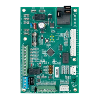
Page 6: Physical Dimensions And Layout
CXM2 UNIT CONTROLS– AOM Models: Physical Dimensions and Layout CXM2 Compressor Constant Torque EC PSC (Single-Stage) On-board Fuse - CE Safeties: HP, LP, LT, LT2 24VAC Thermostat Alarm Relay Aux Electric Heat Emergency Shutdown Modbus Comms Part Number Diagnostics/Sensors (EWT, LWT, LAT, CDT) 1.582 1.244 1.183... -
Page 7: Field Selectable Inputs And Dip Switches
CXM2 UNIT CONTROLS– AOM Models: Field Selectable Inputs and DIP Switches CXM2 FIELD-SELECTABLE INPUTS Water Coil Low Temperature Limit Setting Jumper 3 (JW3-LT1 Low Temp) provides field Test Mode selection of temperature limit setting for LT1 of 30°F or Test mode allows the service technician to check 10°F (-1°F or -12°C) (refrigerant temperature). -
Page 8: Safety Features
CXM2 UNIT CONTROLS– AOM Models: Safety Features CXM2 Table 1: DIP Switch Settings DIP Switch Description Options Default Unit Performance DIP 2.1 Enable, Disable Enable Sentinel DIP 2.2 Compressor Staging Stage 1, Stage 2 Modbus DIP 2.3 Modbus Master, Modbus Slave Modbus Master Communications DIP 2.4... -
Page 9: Fault Codes
CXM2 UNIT CONTROLS– AOM Models: Fault Codes CXM2 FAULT CODES CAUTION Do not restart units without inspection and remedy of faulting Lockout: In Lockout mode, the Fault LED begins condition. Equipment damage may occur. flashing fast. The compressor relay is turned off Fault Code 5 –... - Page 10 CXM2 UNIT CONTROLS– AOM Models: Fault Codes CXM2 If a UPS condition occurs, the control immediately monitors to see if the LT1 and LT2 thermistors are enters UPS warning. The status LED remains lit as if connected and operating properly. If the control is in the control is in Normal mode (See Table 2).
- Page 11 CXM2 UNIT CONTROLS– AOM Models: Fault Codes CXM2 Fault Code 13 – Low Water flow: The control If communication with the sensor is re-established recognizes a low water flow fault if: or the RDS stops sensing a refrigerant leak , the unit resumes normal operation 5 minutes after the RDS In applications with vFlow®...
-
Page 12: Operating Descriptions
CXM2 UNIT CONTROLS– AOM Models: Operating Descriptions CXM2 Power Up: The unit will not operate until all the inputs Emergency Heat: In Emergency Heat mode, the and safety controls are checked for normal conditions. selected fan output is activated and EH1 is turned on immediately. -
Page 13: Special Cxm2 Application Note And Other Outputs
CXM2 UNIT CONTROLS– AOM Models: Special CXM2 Application Note and Other Outputs CXM2 SPECIAL CXM2 APPLICATION NOTES Communications: The CXM2 has a single RS-485 communications port that provides communication ESD: ESD is the input for Emergency-Shutdown mode. capabilities for communicating thermostats or When the ESD input is connected to Ground C, all connecting with other communicating controls. - Page 14 CXM2 UNIT CONTROLS– AOM Thermostat Inputs with Resulting Demands Models: and Sensor Calibration CXM2 Table 3: Thermostat Inputs with Resulting Demands Thermostat Operating Modes Input Output Mode No Demand ON/OFF ON/OFF Fan Only ON/OFF ON/OFF Cooling Heating Heating 2 Stage Emergency Heat 1 ON/OFF = Either ON or OFF;...
-
Page 15: Nominal Resistance Per Temperature
CXM2 UNIT CONTROLS– AOM Models: Nominal Resistance per Temperature CXM2 Table 5: Nominal Resistant per Temperature Temp Temp Resistance Temp Temp Resistance Temp Temp Resistance Temp Temp Resistance (ºC) (ºF) (kOhm) (ºC) (ºF) (kOhm) (ºC) (ºF) (kOhm) (ºC) (ºF) (kOhm) -17.8 85.34 68.0... -
Page 16: Basic Troubleshooting Information And Service And Application Notes
CXM2 UNIT CONTROLS– AOM Basic Troubleshooting Information and Models: Service and Application Notes CXM2 GENERAL TROUBLESHOOTING Test Mode: To enter Test mode for 30 minutes, press the Test Basic CXM2 Control troubleshooting in general is button. For diagnostic ease at a conventional best summarized as simply verifying inputs and thermostat, the Alarm Relay cycles during Test mode. -
Page 17: Configuration And Advanced Troubleshooting
CXM2 UNIT CONTROLS– AOM Models: Configuration and Advanced Troubleshooting CXM2 GENERAL provides the ability to select the Heat Pump Family, Unit Size, Blower Type, and Loop Type. Making these To properly configure and troubleshoot advanced selection configurations is not required. This is an control features, and to aid in troubleshooting basic optional step only. - Page 18 CXM2 UNIT CONTROLS– AOM Models: Configuration and Advanced Troubleshooting CXM2 CXM2 MASTER/SLAVE ADDRESSING Fault History: In addition to the fault code, the CXM2 stores the status of all control inputs and Multiple CXM2 controls may be controlled from outputs when a fault condition is detected. a single communicating thermostat;...
-
Page 19: Cxm2 Functional Troubleshooting Flow Chart
CXM2 UNIT CONTROLS– AOM Models: CXM2 Functional Troubleshooting Flow Chart CXM2 Actual area is 7.25” w x 8.875”h Guides indicate .125” bleed all around Use the following troubleshooting flow chart and tables on the following pages to find the appropriate troubleshooting strategies for the CXM2 control and most water source heat pump applications. -
Page 20: Functional Troubleshooting
CXM2 UNIT CONTROLS– AOM Models: Functional Troubleshooting CXM2 CAUTION Do not restart units without inspection and remedy of faulting condition. Equipment damage may occur. Fault Htg Clg Possible Cause Solution Check line voltage circuit breaker and disconnect. Check for line voltage between L1 and L2 on the contactor. Main power problems Green Status LED Off Check for 24VAC between R and C on CXM2/DXM2.5. - Page 21 CXM2 UNIT CONTROLS– AOM Models: Functional Troubleshooting CXM2 Table continued from previous page. Fault Htg Clg Possible Cause Solution Check power supply and 24VAC voltage before and during operation. Check power supply wire size. Under Voltage Check compressor starting. Need hard start kit? Over/Under Voltage Code 7 Check 24VAC and unit transformer.
- Page 22 CXM2 UNIT CONTROLS– AOM Models: Functional Troubleshooting CXM2 Table continued from previous page. Fault Htg Clg Possible Cause Solution Set for cooling demand and check 24VAC on RV coil and at CXM2/DXM2.5 board. Reversing valve If RV is stuck, run high pressure up by reducing water flow and while operating engage and disengage RV coil voltage to push valve.
-
Page 23: Performance Troubleshooting
CXM2 UNIT CONTROLS– AOM Models: Performance Troubleshooting CXM2 Symptom Htg Clg Possible Cause Solution Dirty filter Replace or clean. Check for dirty air filter and clean or replace. Reduced or no airflow in heating Check fan motor operation and airflow restrictions. Too high of external static? Check static vs. - Page 24 CXM2 UNIT CONTROLS– AOM Models: Performance Troubleshooting CXM2 Table continued from previous page. Symptom Htg Clg Possible Cause Solution Thermostat wiring Check G wiring at heat pump. Jumper G and R for fan operation. Jumper G and R for fan operation. Check for line voltage across blower relay contacts.
- Page 25 CXM2 UNIT CONTROLS– AOM Models: Notes CXM2 w w w. c l i m a t e m a s t e r. c o m U p d a t e d : J u l y 2 4 , 2 0 2 4 PA G E : 2 5...
- Page 26 CXM2 UNIT CONTROLS– AOM Models: Notes CXM2 PA G E : 2 6 U p d a t e d : J u l y 2 4 , 2 0 2 4 w w w. c l i m a t e m a s t e r. c o m...
- Page 27 CXM2 UNIT CONTROLS– AOM Models: Notes CXM2 w w w. c l i m a t e m a s t e r. c o m U p d a t e d : J u l y 2 4 , 2 0 2 4 PA G E : 2 7...
-
Page 28: Revision History
CXM2 UNIT CONTROLS– AOM Models: Revision History CXM2 Date Section Description Field Selectable Inputs and DIP 7/24/24 Updated Test mode duration from 20 to 30 minutes Switches, Basic Troubleshooting 05/24/24 Updated document design and added CXM2 Board Identification section 7300 SW 44th St. | Oklahoma City, OK 73179 *97B0137N01* Phone: 800.299.9747 www.climatemaster.com...
Need help?
Do you have a question about the ClimateMaster CXM2 and is the answer not in the manual?
Questions and answers