Nibe SMO 20 User Manual
Control module
Hide thumbs
Also See for SMO 20:
- User manual (76 pages) ,
- Installer manual (64 pages) ,
- Manual (15 pages)
Table of Contents
Advertisement
Quick Links
Advertisement
Table of Contents

Related Manuals for Nibe SMO 20


Summary of Contents for Nibe SMO 20
- Page 1 User manual Control module NIBE SMO 20 UHB EN 2235-1 731343...
- Page 2 12 hrs To increase the amount of hot water temporarily (if a water heater is installed for your SMO 20), first turn the control knob to select menu 2 (water droplet) and then press the OK button twice. Read more about the settings on page temporary lux.
-
Page 3: Table Of Contents
2 The control module – the heart of the house Control module's function Contact with SMO 20 Maintenance of SMO 20 3 SMO 20 – at your service Set the indoor climate Set the hot water capacity Get information Adjust the heat pump... -
Page 4: Important Information
_ _ _ _ _ _ _ _ _ _ _ _ _ _ _ _ _ _ _ _ _ _ _ _ _ _ _ _ _ _ _ _ _ _ _ _ _ Signed ____________________________________________________________ Chapter 1 | Important information NIBE SMO 20... -
Page 5: Safety Information
Rights to make any design or technical modifications are reserved. ©NIBE 2022. SMO 20 must be installed via an isolator switch. The cable area has to be dimen- sioned based on the fuse rating used. If the supply cable is damaged, only NIBE, its service representative or similar au- thorised person may replace it to prevent any danger and damage. - Page 6 The serial number can be found on the top of the cover for the control module and in the info menu (menu 3.1). Serial number Caution You need the product's (14 digit) serial number for servicing and support. Chapter 1 | Important information NIBE SMO 20...
-
Page 7: Smo 20 - An Excellent Choice
SMO 20 is easy to install together with a compatible NIBE air/water heat pump. When installing, the control module is connected to the heat pump, which enables you to see any heat pump alarms in SMO 20. The size of the control module means that it can be installed on indoor walls for easy access to control your installation. -
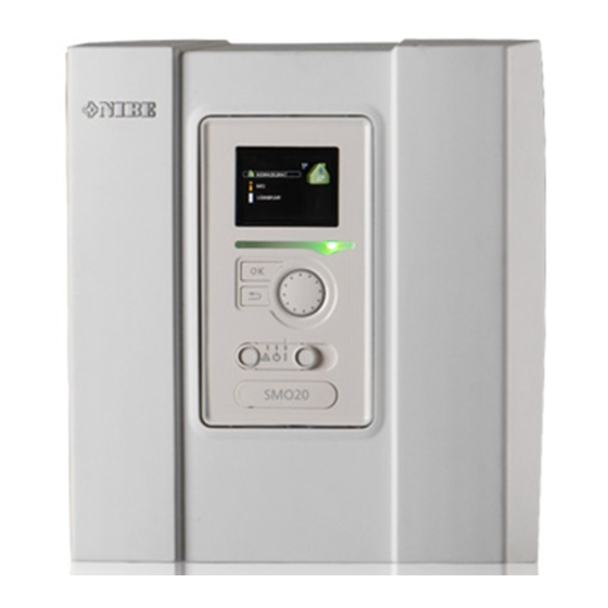
Page 8: The Control Module - The Heart Of The House
Control knob Switch SMO 20 USB port There is a display unit on the front of the control module, which is used to communicate with SMO 20. Here you: • switch on, switch off or set the installation to emergency mode. •... - Page 9 The USB port is hidden beneath the plastic badge with the product name on it. The USB port is used to update the software. Visit nibeuplink.com and click the "Software" tab to download the latest software for your installation. NIBE SMO 20 Chapter 2 | The control module – the heart of the house...
- Page 10 Display of temperature and other operating information and access to the alarm log. See page 28. MENU 4 - MY SYSTEM Setting time, date, language, display, operating mode etc. See page 31. Chapter 2 | The control module – the heart of the house NIBE SMO 20...
- Page 11 This symbol appears if periodic increase or lux mode for the hot water is activated. This symbol indicates whether "holiday setting" is active in 4.7. This symbol indicates whether SMO 20 has contact with NIBE Uplink. This symbol is visible in installations with active solar accessories.
- Page 12 Mark the applicable option. One of the options is pre-selected (white). Press the OK button to confirm the selected option. The selected option has a green tick. Chapter 2 | The control module – the heart of the house NIBE SMO 20...
- Page 13 To change character table, press the Back button. If a menu only has one character set the keyboard is displayed directly. When you have finished writing, mark "OK” and press the OK button. NIBE SMO 20 Chapter 2 | The control module – the heart of the house...
- Page 14 Use the control knob to select the help symbol. Press the OK button. The help text often consists of several windows that you can scroll between using the control knob. Chapter 2 | The control module – the heart of the house NIBE SMO 20...
-
Page 15: Maintenance Of Smo 20
Maintenance of SMO 20 REGULAR CHECKS Your heat pump requires minimal maintenance after commissioning. On the other hand, it is recommended that you check your installation regularly. For more information regarding the maintenance of heat pumps and/or ac- cumulator tanks/water heaters, refer to the relevant manual. -
Page 16: Smo 20 - At Your Service
To change the room temperature, use the control knob to set the desired temperature in the display. Confirm the new setting by pressing the OK button. The new temperature is shown on the right-hand side of the symbol in the display. Chapter 3 | SMO 20 – at your service NIBE SMO 20... - Page 17 One step is usually enough to change the room temperature by one degree, but in some cases several steps may be required. If a room sensor is installed and activated, the desired room temperature (°C) is set during the time periods. NIBE SMO 20 Chapter 3 | SMO 20 – at your service...
- Page 18 MENU 1.3.2 - COOLING Here you can schedule when cooling is permitted in the accommodation for up to two different time periods per day. Chapter 3 | SMO 20 – at your service NIBE SMO 20...
- Page 19 Settings for cooling. own curve Setting own curve for heating and cooling. point offset Setting the offset of the heating curve or cooling curve at a specific outdoor temperature. NIBE SMO 20 Chapter 3 | SMO 20 – at your service...
-
Page 20: Contact With Smo
Cooling in 2-pipe system SMO 20 contains a built-in function for operating cooling in a 2-pipe system down to 7 °C, factory setting 18 °C. This requires that the outdoor module can perform cooling. (See the Installer Manual for your air/water heat pump.) If the outdoor module is permitted to run cooling, the cooling menus are activated in the display on SMO 20. - Page 21 In menu 1.9.3 you select heating or cooling, in the next menu (min. supply temp.heating/cooling) set the minimum temperature on the supply temperature to the climate system. This means that SMO 20 never calculates a tem- perature lower than that set here.
- Page 22 (Displayed if cooling in 2-pipe system is activated.) Setting range: 0 – 48 h Factory setting: 2 You can use SMO 20 to control the cooling in your house during hot periods of the year. Chapter 3 | SMO 20 – at your service NIBE SMO 20...
- Page 23 Here you can set how high the room temperature can increase above the desired temperature before SMO 20 switches to cooling operation. larm rumsgivare kyla This is where you set whether SMO 20 is to initiate an alarm if the room sensor is disconnected or breaks during cooling operation. start active cooling Here you can set when active cooling is to start.
- Page 24 If it is cold in the house, at, for example -2 °C, "outdoor temp. point" is set to "-2" and "change in curve" is increased until the desired room temperature is maintained. Caution Wait 24 hours before making a new setting, so that the room temperature has time to stabilise. Chapter 3 | SMO 20 – at your service NIBE SMO 20...
-
Page 25: Set The Hot Water Capacity
The function is activated immediately when a time period is selected and confirmed using the OK button. The re- maining time for the selected setting is shown to the right. When the time has run out SMO 20 returns to the mode set in menu 2.2. Select “off" to switch off temporary lux MENU 2.2 - COMFORT MODE... - Page 26 MENU 2.9 - ADVANCED Menu advanced has orange text and is intended for the advanced user. This advanced 2.9 menu has several sub-menus. periodic increase hot water recirc. Chapter 3 | SMO 20 – at your service NIBE SMO 20...
- Page 27 "operating time" decide how long the hot water circulation pump must run per operating instance. "downtime" decide how long the hot water circulation pump must be stationary between operating instances. Hot water circulation is activated in menu 5.4 "soft inputs and outputs". NIBE SMO 20 Chapter 3 | SMO 20 – at your service...
-
Page 28: Get Information
-5.6 °C ext heat. med. pump runs charge pump speed 57 % Symbols in this menu: Compressor Heating Addition Hot water Cooling Heating medium pump (orange) Solar accessory Chapter 3 | SMO 20 – at your service NIBE SMO 20... - Page 29 To read off an average temperature Turn the control knob so that the ring on the shaft with the week number is marked. week Press the OK button. NIBE SMO 20 Chapter 3 | SMO 20 – at your service...
- Page 30 4. You can now select to take read outs for different weeks by turning the control knob to the right or left and read off the average temperature. 5. Press the OK or Back button to exit read off mode. Chapter 3 | SMO 20 – at your service NIBE SMO 20...
-
Page 31: Adjust The Heat Pump
Settings of control module work mode. MENU 4.1 - PLUS FUNCTIONS Settings for any additional functions installed in SMO 20 can be made in the sub menus. MENU 4.1.3 - INTERNET Here you make the settings for connecting SMO 20 via NIBE Uplink, which internet 4.1.3... - Page 32 NOTE After disconnecting all users none of them can monitor or control your installation via NIBE Uplink without requesting a new connection string. MENU 4.1.3.8 - TCP/IP SETTINGS Here, you can set TCP/IP settings for your installation. tcp/ip settings 4.1.3.8...
- Page 33 "-1". If a room sensor is installed and activated, the desired room temperature is instead reduced by 1 °C. NOTE The function must be connected and activated in your SMO 20. MENU 4.1.6 - SMART PRICE ADAPTION™ affect room temperature smart price adaption 4.1.6...
- Page 34 This is where you set that part of your installation (room temperature, hot water temperature) that will benefit from the surplus solar electricity. When the solar panels produce more electricity than SMO 20 requires, the temperature in the property is adjusted and/or the temperature of the hot water is increased.
- Page 35 You can deselect this function when you do not wish to have cooling in operation. MENU 4.4 - TIME & DATE NIBE SMO 20 Chapter 3 | SMO 20 – at your service...
- Page 36 24 h 12 h date Time and date are set automatically if the heat pump is connected to NIBE Uplink. To obtain the correct time, the time zone must be month set. year MENU 4.6 - LANGUAGE Choose the language that you want the information to be displayed in here.
- Page 37 It cannot be set "stop additional heat" higher than "stop heating". filtering time: You can also set the time (filtering time) over which the average temperature is calculated. If you select 0, the current outdoor temperature is used. NIBE SMO 20 Chapter 3 | SMO 20 – at your service...
- Page 38 Time period: The start and stop time for the selected day for scheduling are selected here. Blocking: The desired blocking is selected here. Conflict: If two settings conflict with each other, a red exclamation mark is displayed. Chapter 3 | SMO 20 – at your service NIBE SMO 20...
- Page 39 Time period: The start and stop time for the selected day for scheduling are selected here. Conflict: If two settings conflict with each other, a red exclamation mark is displayed. NIBE SMO 20 Chapter 3 | SMO 20 – at your service...
- Page 40 Activ- ation takes place by ticking "de-icing fan” in the menu, after which de-icing EB101 is performed once. fan de-icing Continuous fan de-icing Chapter 3 | SMO 20 – at your service NIBE SMO 20...
-
Page 41: Disturbances In Comfort
Disturbances in comfort In most cases, SMO 20 notes a malfunction (a malfunction can lead to disruption in comfort) and indicates this with alarms, and instructions for action, in the display. Info-menu All the installation’s measurement values are gathered under menu 3.1 in the control module’s menu system. Ex- amining the values in this menu can often make it easier to identify the source of the fault. - Page 42 Mixing valve (if there is one installed) set too low. – Adjust the mixer valve. • SMO 20 in incorrect operating mode. – Enter menu 4.2. If mode "auto" is selected, select a higher value on "stop additional heat" in menu 4.9.2. –...
-
Page 43: Add. Heat Only
Mark ”add. heat only” using the control knob and then press the OK button. 3. Return to the main menus by pressing the Back button. Caution When commissioning without NIBE air/water heat pump, the "communication error" alarm may appear in the display. NIBE SMO 20... -
Page 44: Technical Data
Technical data Detailed technical specifications for this product can be found in the installation manual (nibe.eu). Chapter 5 | Technical data NIBE SMO 20... -
Page 45: Glossary
Indicates the time the average outdoor temperature is calculated on. FLOW PIPE The line in which the heated water is transported from the heat pump out to the house heating system (radiat- ors/heating coils). NIBE SMO 20 Chapter 6 | Glossary... - Page 46 RADIATOR Another word for heating element. They must be filled with water in order to be used with SMO 20. RETURN PIPE The line in which the water is transported back to the heat pump from the house heating system (radiators/heating coils).
-
Page 47: Item Register
Glossary, 45 Help menu, 14 Important information Installation data, 4 Safety information, 5 Serial number, 6 SMO 20 – An excellent choice, 7 Installation data, 4 Maintenance of SMO 20, 15 Regular checks, 15 Saving tips, 15 Manage alarm, 41... - Page 48 Serial number, 6 Set the hot water capacity, 25 Set the indoor climate, 16 Setting a value, 13 SMO 20 – An excellent choice, 7 SMO 20 – at your service, 16 Adjust the installation, 31 Get information, 28 Set the hot water capacity, 25...
-
Page 51: Contact Information
Tel: +48 (0)85 66 28 490 Hannabadsvägen 5, 285 21 Markaryd Tel. +41 (0)58 252 21 00 biawar.com.pl Tel: +46 (0)433-27 3000 info@nibe.ch info@nibe.se nibe.ch nibe.se For countries not mentioned in this list, contact NIBE Sweden or check nibe.eu for more information. - Page 52 WS release date: 2022-07-08 07:14 Publish date: 2022-10-03 09:59 This is a publication from NIBE Energy Systems. All product illustrations, facts and data are based on the available information at the time of the publication’s approval. NIBE Energy Systems makes reservations for any factual or printing errors in this publication.
Need help?
Do you have a question about the SMO 20 and is the answer not in the manual?
Questions and answers