
Related Manuals for 3onedata IES605-2D series


Summary of Contents for 3onedata IES605-2D series
-
Page 1: User Manual
IES605-2D series Industrial Ethernet switch User manual Shenzhen 3onedata Technology Co.,Ltd Tel: +86-755-26702668 Fax: +86-755-26703485 www.3onedata.com... -
Page 2: Packing List
【Summarize】 IIES605-2D series is an industrial, management, redundant industrial Ethernet switch and integrate 2 port serial device servers. It included 1. IES605-2D (RS-232)-P (12/48VDC), Support 5 port 10/100Base T(X) and 2 port RS-232, 2. IES605-2DI (RS-485)-P (12/48VDC), Support 5 port 10/100BaseT(X) and 2 port RS-485/422, 3. -
Page 3: Panel Layout
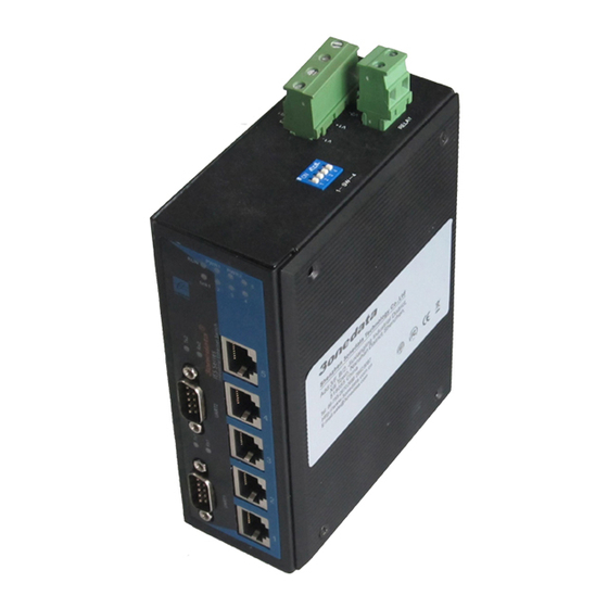
Industrial Ethernet switch(IES605-2D series)ⅹ 1 User manual ⅹ 1 CD ⅹ 1 Certificate of quality ⅹ 1 Warranty card ⅹ 1 Please inform us or our distributor if your equipments have been damaged or lost any accessories, we will try our best to satisfy you. - Page 4 Back view Top and below view IES605-2D(RS-232)-P(12/48VDC) 1. PWR1/PWR2 power supply 2. Ground screw 3. Relay output terminal block 4. DIP switch (4 bits) 5. DIN-Rail 6. LED indicator 7. 10/100Base-TX RJ45 port 8. RS-232 port IES605-2DI(RS-485)-P(12/48VDC) 1. PWR1/PWR2 power supply 2.
- Page 5 IES605-1F-2D(RS-232)-P(12/48VDC) 1. PWR1/PWR2 power supply 2. Ground screw 3. Relay output terminal block 4. DIP switch (4 bits) 5. DIN-Rail 6. LED indicator 7. 100Base-FX fiber port 8. RS-232 port 9. 10/100Base-TX RJ45 port IES605-1F-2DI(RS-485)-P(12/48VDC) 1. PWR1/PWR2 power supply 2. Ground screw 3.
-
Page 6: Appearance And Dimension
7. 100Base-FX fiber port 8. RS-232 port 9. 10/100Base-TX RJ45 port IES605-2F-2DI(RS-485)-P(12/48VDC) 1. PWR1/PWR2 power supply 2. Ground screw 3. Relay output terminal block 4. DIP switch (4 bits) 5. DIN-Rail 6. LED indicator 7. 100Base-FX fiber port 8. RS-485/422 port 9. -
Page 7: Power Supply Input
Top view The relay owns two contacts of the terminal block on the top panel of IES605-2D series. It is used to detect both power failure and port failure. The two wires attached to contacts form an open circuit when: (1) IES605-2D series has lost power supply from one of the DC power inputs. -
Page 8: Communication Connector
configure ( OFF is default factory) ,1 and 2 keep for future function. 3 is for upgrade. 4 is recovery default factory. Please power off and power on when you change the status of DIP switch. 【Communication connector】 10/100BaseT(X) Ethernet port The pinout of RJ45 port display as below, connect by UTP or STP. - Page 9 MDI-X (Cross over cable) MDI/MDI-X auto connection makes IES605-2D easy to use for customers without considering the type of network cable. 100Base-FX Fiber port 100Base-FX full-duplex SM or MM port, SC/ST/FC type .The fiber port must be used in pair, TX (transmit) port connect remote switch’s RX (receive) port;...
-
Page 10: Led Indicator
RS-232 — DB9 male (RS-232) RS-485/422 port: RS-422 RS-485 RS-485/422 【LED indicator】 IES605-2D series LED indicator light on the front panel .the function of each LED is described in the table as below:... -
Page 11: Installation
System status LED Indicator Description P1 connection regularly PWR1 P1 Power supply have no connection or unwonted P2 connection regularly PWR2 P2 Power supply have no connection or unwonted Power, port have alarm Alarm Power, port have no alarm Device unwonted Device working steadily, Blinking per Blinking second... - Page 12 3. Examine whether the cables be seemly or not (less than 100m) according to reasonable scheme. 4. Screw, nut, tool provide by yourself. 5. Power: redundant 12-48VDC o power input 6. Environment: working temperature -40~75℃ Relative humidity 5%~95% DIN rail installation In order to use in industrial environments expediently, IES605-2D series adopt 35mm DIN-Rail installation, the installation steps as fellows:...
-
Page 13: Specification
laying position need to match construction requirements, and cable length depends on actual position; 4. All the cable cannot have break-down and terminal in the middle; 5. Cables should be straight in the hallways and turning; 6. Cable should be straight in the groove, and cannot beyond the groove in case of holding back the inlet and outlet holes. - Page 14 Interface 100M Ethernet: 10/100Base-TX self-adapt RJ45 port. 100M fiber port: 100Base-FX (SC/ST/FC) Alarm port: 2 bit 7.62mm terminal block, 1 channel relay alarm output Serial RS-232 signal: TXD, RXD, RTS, CTS, DTR, DSR, GND RS-422 signal: T+, T-, R+, R-, GND RS-485 signal: D+, D-, GND Parity: None, Even, Odd, Space, Mark Data bit: 5bit, 6bit, 7bit, 8bit...
- Page 15 System indicator: Run Ethernet port indicator: Link/Act(1-5) Serial port indicator: TX (1-2), RX (1-2) Power supply Input voltage: 24VDC (12~48VDC) Terminal block: 4 bits 7.62mm terminal block IES605-2D(RS-232)-P(12/48VDC) None load consumption: 0.9W@24VDC Full load consumption: 1.6 W@24VDC IES605-2DI(RS-485)-P(12/48VDC) None load consumption: 1.3W@24VDC Full load consumption: 1.9 W@24VDC ...
- Page 16 Dimension(W×H×D): 136mm×52mm×105mm Weight: 900g Environmental Operating Temperature: -45°C to 75°C Storage Temperature: -45°C to 85°C Relative Humidity: 10 to 95% (non-condensing) Standard EMI: FCC Part 15, CISPR (EN55022) class A EMS: EN61000-4-2 (ESD), Level 4 EN61000-4-3(RS), Level 3 EN61000-4-4 (EFT), Level 4 EN61000-4-5 (Surge), Level 4 EN61000-4-6(CS), Level 3 EN61000-4-8(PFM), Level 5...
Need help?
Do you have a question about the IES605-2D series and is the answer not in the manual?
Questions and answers