
Related Manuals for Queclink GL500


Summary of Contents for Queclink GL500
-
Page 1: User Manual
GV300 User manual GL500 GSM/GPRS/GPS Tracker User Manual TRACGL500UM001 Revision: 1.01 sales@eddywireless.com... - Page 2 TRACGL500UM001 General Notes Queclink offers this information as a service to its customers, to support application and engineering efforts that use the products designed by Queclink. The information provided is based upon requirements specifically provided to Queclink by the customers. Queclink has not undertaken any independent search for additional relevant information, including any information that may be in the customer’s possession.
-
Page 3: Table Of Contents
3.1. Opening the Case ......................11 3.2. Closing the Case........................ 11 3.3. Installing a SIM Card ......................11 3.4. Installing the Internal Backup Battery................12 3.5. Power On the Device......................13 3.6. Direction of GL500 Placed ....................13 3.7. Device Status LED ......................14 TRACGL500UM001 - 3 -... - Page 4 GL500 User Manual Table Index Table 1. GL500 Protocol Reference..................7 Table 2. Terms and Abbreviations...................7 Table 3. Parts List ........................9 Table 4. Description of 8 PIN Connections ................10 Table 5. Definition of Device status and LED ..............14 TRACGL500UM001 - 4 -...
- Page 5 GL500 User Manual Figure Index Figure 1. Appearance of GL500 ..................8 Figure 2. The 8 PIN connector on the GL500 ..............10 Figure 3. Opening the Case .................... 11 Figure 4. Closing the Case....................11 Figure 5. SIM Card Installation ..................12 Figure 6.
- Page 6 GL500 User Manual Revision History Revision Date Author Description of change 1.00 2012-6-11 Cid Xu Initial 1.01 2013-6-3 Tony.Pei Add the direction of GL500 placed TRACGL500UM001 - 6 -...
-
Page 7: Introduction
1000days. With built-in motion sensor, GL500 can also detect the motion of asset all the time and give a warning message. Based integrated @track protocol, the GL500 can communicate with a backend... -
Page 8: Product Overview
GL500 User Manual 2. Product Overview 2.1. Check Parts List Before starting, check all the following items have been included with your GL500. If anything is missing, please contact your supplier. Figure 1. Appearance of GL500 TRACGL500UM001 - 8 -... -
Page 9: Parts List
GL500 Data Cable (Optional) GL500 MCU Download Kit (Optional) 2.3. Interface Definition The GL500 has an 8 PIN interface connector. It contains the connections for power, RS232, MCU Interface, etc. The sequence and definition of the 8PIN connector are shown in following figure:... -
Page 10: Table 4. Description Of 8 Pin Connections
GL500 User Manual Figure 2. The 8 PIN connector on the GL500 Table 4. Description of 8 PIN Connections Index Description Comment CHARGER_IN External DC power input, 5V Not connected BB_RXD BB UART RXD BB_TXD BB UART TXD MCU_RESET MCU CHIP RESET SIGNAL... -
Page 11: Getting Started
GL500 User Manual 3. Getting Started 3.1. Opening the Case Figure 3. Opening the Case Use the Screwdriver to remove the screws, and then open the case. 3.2. Closing the Case Figure 4. Closing the Case Place the cover in the correct position as shown in upon figure. Please note the battery direction and SIM Card direction, and then tighten the screws with a Screwdriver. -
Page 12: Installing The Internal Backup Battery
Figure 6. Backup Battery Installation There have 2pcs internal CR123A battery for GL500, Insert the battery into the holder as shown in upon figure, please note that the polarity mark of the battery and battery holder need to be consistent. -
Page 13: Power On The Device
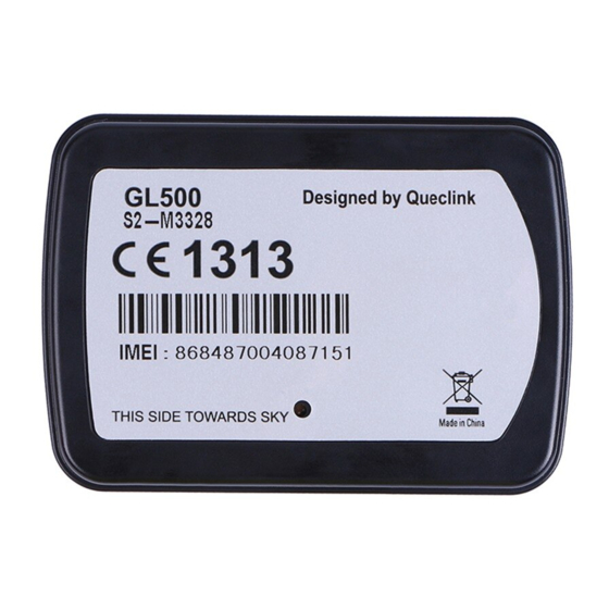
GL500 User Manual 3.5. Power On the Device After inserted the Battery, GL500 will power on automatically, the Status LED will start work, detail description in the next section. Blue Green GSM Figure 7. GL500 Status LED 3.6. Direction of GL500 Placed The side with label should towards sky to ensure there is good GPS signal can be recieved. -
Page 14: Device Status Led
GL500 User Manual 3.7. Device Status LED Table 5. Definition of Device status and LED Device status LED status Device is searching GSM network. Fast flashing (Green) (Note1) Device has registered to GSM network. Slow flashing (Note2) SIM card needs pin code to unlock.
Need help?
Do you have a question about the GL500 and is the answer not in the manual?
Questions and answers