
Related Manuals for QuiQue's Aircraft YAK-54


Summary of Contents for QuiQue's Aircraft YAK-54
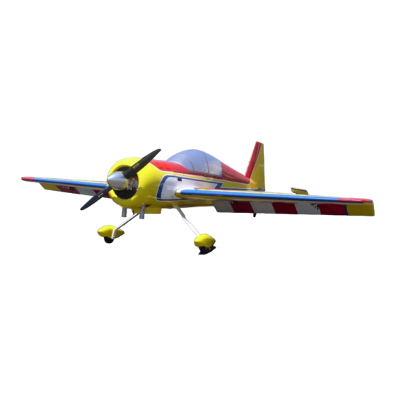
- Page 1 Semi Scale Yak-54, ARF 102” Generation II ASSEMBLY MANUAL Specifications Wingspan: 102 in Length Including Spinner: 91 in Wing Area: 1,975 sq in Weight (RTF): 25-28 lb Recommended Engines: 100-110cc...
-
Page 2: Table Of Contents
Table of Contents Quique’s Aircraft Company Covering Colors Going Over the Covering Hardware Supplied Additional Required Tools and Adhesives Servo Selection Using the Manual Warning Warranty Information Section 1-Preparing Fuselage Section 2-Horizontal Stab Installation Section 3-Elevator, Rudder and Aileron Control Horn Installation Section 4-Preparation and Installation of Hinges Section 5-Wing Anti-Rotation Pins and Servo Installation Section 6-Tail Wheel Installation... -
Page 3: Quique's Aircraft Company
Website:www.QQAircraft.com Online-Support:http://www.rcuniverse.com/forum/forumid_437/tt.htm Quique and I want to express our thanks to you for choosing our 102” Yak-54. We think that you will enjoy one of the best flying model aerobatic airplanes available. It is patterned after the 37% Yak-54 which took First Place honors at 2006 Don Lowe Masters Champion and 2006 Tucson Free Style Champion. -
Page 4: Covering Colors
Hanu872 Going Over the Covering Before beginning the assembly of your Yak-54, remove each part from its bag for inspection. If you find any wrinkles in the covering, use a heat gun or covering iron to remove them. Use caution while working around areas where the colors overlap to prevent separating the colors. -
Page 5: Hardware Supplied
Hardware Supplied Pull/Pull Rudder 30 Hinges and Wing pins/clips Tail Wheel Canopy hardware Aileron/Elevator Titanium rods & ball links Fuel Tank Cowl hardware Optional Dubro Hardware to complete your Assembly: Wheels and Axles Control Horn System... -
Page 6: Additional Required Tools And Adhesives
Additional Required Tools and Adhesives • Covering/Trim iron • Xacto knife, #11 blade • Pacer hinge glue (PT-55) • 5, 15 and 30-minute epoxy • Petroleum jelly/Lithium grease • Acetone/Alcohol swabs • Felt-tip marker • Pencil and Marker • Ruler •... - Page 7 All Other Parts Required to Complete the Aircraft • DA100 or similar engine • MTW 75 Canisters with 50mm drop down header or Stock Mufflers or similar set up for different engine • 1.5” Aluminum stand offs • (8) JR 8611a or similar Digital servo •...
-
Page 8: Servo Selection
Please do not risk your plane by using low torque or analog servos. This Yak-54 has large control surfaces and fully capable of any maneuvers that a pilot is able to perform. Therefore, using weak servos will increase chance of flutter and may result in a crash. -
Page 9: Section 1-Preparing Fuselage
Section 1-Preparing Fuselage Required Tools and Adhesive • Xacto knife, #11 Blade • Trim Iron Step 1 Use an Xacto knife with a # 11 blade and cut away the film covering on both sides of the fuselage for the wing openings, Figure 1. -
Page 10: Section 2-Horizontal Stab Installation
Section 2-Horizontal Stab Installation Required Tools and Adhesive Step 3 • Rat-tail File Prepare the C/F anti-rotation pins by • Acetone using coarse sandpaper and rough • Xacto knife, #11 Blade up the end of the pin where it will be •... - Page 11 holes in the fuse sides slightly with a small rat tail file. Very Important: After completing the model and flying it, in case you noticed any play in the stab, please glue the horizontal stab tube in place in the fuselage with epoxy and micro-balloons.
-
Page 12: Section 3-Elevator, Rudder And Aileron Control Horn Installation
Section 3-Elevator, Rudder and Aileron Control Horn Installation Required Tools and Adhesive covering film on the top of the elevator. • Xacto knife, #11 Blade Be sure that you do not put too much • 5-10 minute epoxy epoxy in the hole and on the screw. •... - Page 13 Use the Dubro heavy duty dual pull- 8-32X3 round Slotted/Phillips Zinc pull system Cat. No. 882. Insert the Machine screw at Lowes or similar 8-32 threaded rod for the rudder supplier. We include those screws in control horn. our optional Du-Bro package. Step 3 Step 3 Take the screw out and apply a thin...
-
Page 14: Section 4-Preparation And Installation Of Hinges
Section 4-Preparation and Installation of Hinges Required Tools and Adhesive • Xacto knife, #11 Blade • Lithium grease/Petroleum Jelly • Toothpicks • Pacer hinge glue (PT-55) The hinge slots are already cut in the balsa at all hinge locations on both the fixed surfaces and the moveable surfaces. - Page 15 Step 1 Step 3 Use a # 11 blade to open the flat hinge slot. Make a V- cut in the fixed and The hinge slots will have to have a control surface area along the slot larger opening cut out just on either location of the flat hinge.
- Page 16 Be very careful not to get any grease For each aileron, cut 44 1/4”x1” of etc. on the flat part of the hinges. bright yellow ultracote and seal the Also remember that you always glue hinge line from top using a straight the hinges in to the fixed surfaces edge and trim iron.
-
Page 17: Section 5-Wing Anti-Rotation Pins And Servo Installation
Section 5-Wing Anti-Rotation Pins and Servo Installation Required Tools and Adhesive • 5-15 minute epoxy • Ruler • Coarse sandpaper • Acetone/Alcohol swab • Thin C/A • Micro balloons • (2) 24” servo extensions • (2) 1.5” aluminum servo arms •... - Page 18 in the end of the pins to make sure the front and rear pins are vertical as this is very important Step 6 Step 4. You will find some ¼” I.D. O-rings Let the epoxy harden. Stand the and washers with the wing anti- wing on its wing tip and run some rotation package of parts.
- Page 19 Step 8 Plug a 24" servo extension onto the outboard servo. Either tie the servo leads together, using a commercially available connector, or use unwaxed dental floss to secure the extensions to prevent them from coming loose during flight. Step 9 Figure 17 To run the servo extensions, use a Step10...
- Page 20 Figure 18 Step 13 You need to use matchboxes for best results. Make sure that servos are not fighting each other throughout the travel. Follow matchbox instructions for proper set up.
-
Page 21: Section 6-Tail Wheel Installation
Section 6-Tail Wheel Installation Required Tools and Adhesive • Drill • Thread lock • Course sandpaper • 5-minute epoxy Step 1 Figure 19 Insert the three screws to attach the tail wheel bracket. Step 2 Attach the small piano wire control steering arm and be sure to use thread lock on all the screws. -
Page 22: Section 7-Elevator Servo Installation
Section 7-Elevator Servo Installation Required Tools and Adhesive • (2) 48” servo extension • Pin vise • 1/16”drill bit • 1 1/4” aluminum servo arms Step 1 Install the servo in its place. Figure 20 Step 2 Pull the servo wire through the rib access holes closest to the tube sleeve. - Page 23 Figure 22 Figure 23 Figure 24...
-
Page 24: Section 8-Rudder Servo And Pull/Pull Installation
Section 8-Rudder Servo and Pull/Pull Installation Required Tools and Adhesive Step 3 • Z-42 thread locker (Pacer) Insert the cable connector sleeve • Thin C/A over the cable through the small end • 0.05 Allen wrench of the connector. Tie a knot and pull •... - Page 25 Figure 27 Figure 26 Step 8 Step 4 After you fly the airplane for 3 to 5 Attach the double CF arm to your flights you will need to readjust the servo arm and mark the holes you cables because they will get to “their want to use to couple the servo to place”.
-
Page 26: Section 9-Engine Mounting
Section 9-Engine Mounting and Throttle Control Installation Required Tools and Adhesive Step 2 • Drill Mark the four engine mounting bolt • 1/8”, ¼” drill bits holes through the template and onto • Sullivan Locking Sleeve Ball the firewall and drill the holes. Joints S560 •... - Page 27 Step 5 Use 1.5” stand offs for both canister or stock muffler installation. Step 6 You can make those stand offs from 1” hardwood dowel that can be bought from a local store like Figure 32 Homedepot. Cut them to the desired length depending on your installation.
- Page 28 Step 1 Remove the covering from the bottom of the fuselage and leave 1/4” ultra-coat, so you can iron the covering down nicely into the opening. Figure 35 Figure 38 Step 2 To avoid cutting the header, remove Figure 36 the covering in front of the landing gear and then remove the stringers.
- Page 29 Keep in mind that if you are using flex headers with the Teflon tape, it is ok to remove the tape if you need more range of motion from the flex portion of the headers. The Teflon tape is supplied on the headers to help alleviate leakage out of the flex portion of the header.
- Page 30 Figure 43 Figure 44 Slide each canister into the canister Once you are satisfied with the fit of tunnel and secure the headers to the the canister support and the engine. Use the supplied gasket or clearance of the canisters, glue the Red, high temperature RTV silicone mount in place near or against the gasket maker to alleviate any leaks...
- Page 31 is approximately 5 inches behind the back of the landing gear. Glue in the ply canister mount with epoxy on both sides to the sides of the fuse former. After the epoxy hardens, add some thick C/A along the bottom of the canister mounting plate, as viewed from the opening in the bottom of the fuse and also along the opposite...
- Page 32 Figure 50 Figure 51...
-
Page 33: Section 10-Landing Gear Installation
Section 10-Landing Gear Installation Step 2 Required Tools and Adhesive • Drill, 3/16”(4.5mm) and 5/16” Landing gear is made of Glass- Epoxy. Before drilling, make sure to drill bit use a piece of wood and clamp it to • Axles Dubro Cat No.249 the gear. - Page 34 Step 3 Using a 3/16” drill bit, drill a hole into the wheel pants. Step 4 With dremel and grinding tool, make a larger pocket around the axle hole to fit the axle hex-nut onto the wheel pants. Figure 57 Step 5 Mount the gear so it is swept forward and adjust the wheel pants to the...
-
Page 35: Section 11-Fuel Tank Installation
Section 11-Fuel Tank Installation Rear Plate: 178mmx45mm. Required Tools and Adhesive • 15-30 minute epoxy • Velcro or tie wraps 18” long • ¼” thick lite-ply or plywood • Sandpaper • Sticky back Velcro Step 1 Assemble the fuel tank hardware as shown. - Page 36 Step 5 For those who want to use a smoke system, there are two ways to install Use industrial strength sticky Velcro your smoke tank. to the top of the tank and plate. This will prevent the tank from moving 1.
-
Page 37: Section 12-Engine Cowling
Section 12-Engine Cowling Required Tools and Adhesive Step 2 • 15-30 minute epoxy • Pencil/Marker Drill a pilot hole, using a 1/16” dia. • Drill & 1/16” drill bit drill bit through the cowl into the four • Masking tape mounting blocks. - Page 38 place it along the canopy hatch and extend the straight edge forward on the cowl beyond the standoff. Put masking tape and mark that horz. line as shown in below picture. Figure 67 Figure 66 To measure the stand-off location, remove the cowl and put the straight edge back on the canopy hatch line and measure down to the stand-off.
-
Page 39: Section 13-Canopy Installation
Section 13-Canopy Installation Required Tools and Adhesive • Xacto knife, #11 blade • Drill • Thin/Medium C/A • 5-minute epoxy Step 1 Figure 69 5-min Epoxy the pin in place. Figure 68 Step 2 Mark the tabs from the holes that are in the fuselage and drill for accepting the blind nuts. -
Page 40: Section 14-Radio Equipment
Section 14-Radio Equipment You are now in the final stages in completing the assembly of your Yak-54. This is how Quique has been mounting his receiver with great success. 1. Apply some beads of medium C/A. 2. Attach a piece of foam the size of the bottom of the receiver to the base. - Page 41 3. CA thick foam to the masking 6. Mount the battery on the tape. plate and wrap it with Velcro straps. These batteries need to be soft mounted. Having foam underneath it and using Velcro will ensure the safety of your battery. Figure 73 4.
- Page 42 Figure 80 Figure 78 2. Remove enough foam to fit the switch and pass the wires. Do not remove more foam than necessary. Figure 81 Ignition Module Installation Use the same method described in RX battery section to mount Figure 79 your ignition module and ignition 3.
- Page 43 Receiver, Regulator and Rudder Matchbox installation Receiver, regulator and rudder match box can be mounted on the rudder tray. Figure 85 Receiver Antenna Guide the antenna through a nyrod and guide the nyrod towards the tail in between the formers. A drop of CA Figure 83 will hold the nyrod to the formers.
-
Page 44: Balancing The Model
Balancing the Model Perhaps one of the most important things that you need to check before you fly your plane is your model C.G. Correctly balancing an aerobatic model is critical to its performance and flight characteristics. An unbalanced model can be very hard to control. -
Page 45: Control Throws
Control Throws Below picture shows you how to measure. Exact number of low rate or high rate is not depicted! Aileron (As shown in Figure 88) Low Rate (Expo 65%) High Rate (Expo 70%) 3 3/8”Up 3 3/4” Up 3 3/8” Down 3 3/4”... - Page 46 Elevator (As shown in Figure 89) Low Rate (Expo 45%) High Rate (Expo 80%) 7/8” Up 3 3/4”-3 7/8” Up 7/8” Down 3 3/4”-3 7/8” Down Figure 89...
- Page 47 Rudder (As shown in Figure 90) Low Rate (Expo 35%) High Rate (Expo 45%) 2 5/8” Right 5” Right 2 5/8” Left 5” Left Figure 90...
-
Page 48: Preflight At The Field
Preflight at the Field Range Test Your Radio Make sure you range check your radio before you attempt to fly your plane. Range check your radio without engine running and your antenna fully collapsed in case of JR 10X remove the antenna and range check with no antenna installed.
Need help?
Do you have a question about the YAK-54 and is the answer not in the manual?
Questions and answers