Table of Contents
Advertisement
Quick Links
Advertisement
Table of Contents

Related Manuals for QuiQue's Aircraft Premier Aircraft QQ Yak 54 35cc


Summary of Contents for QuiQue's Aircraft Premier Aircraft QQ Yak 54 35cc
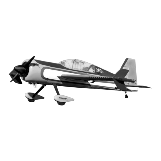
- Page 1 The Original 35cc Assembly Manual...
- Page 2 ATTENTION_ BEFORE ASSEMBLING YOUR QQ YAK 54 35CC OR CONTINUING WITH THIS INSTRUCTION MANUAL, PLEASE VISIT OUR WIKI SUPPORT SITE FOR THE LATEST INFORMATION AND DOCUMENTATION. http://wiki.flexinnovations.com http://wiki.flexinnovations.com/wiki/QQYak54_35cc THE WIKI WILL HAVE THE LATEST PRODUCT & MANUAL UPDATES, FEATURE CHANGES AND AURA 8 AFCS INFORMATION.
-
Page 3: Warranty No�Ce
INTRODUCTION IMPORTANT INFORMATION REGARDING WARRANTY Congratula�ons on the selec�on of your new Premier Aircra� QQ Yak 54 35cc. Please read our Warranty and Liability sec�on before building this product. If Designed by Quique Somenzini, Flex Innova�ons co-founder and world you as the Purchaser or user are not prepared to accept the liability associated aeroba�c champion, this airplane is designed to excel in both precision and 3D with the use of this product, you are advised to return this product aeroba�cs. -
Page 4: Table Of Contents
TABLE OF CONTENTS 76 in. (1930mm) Introduc�on ............Gasoline Engine Installa�on ......17-19 Using this Manual ..........Electric Motor Installa�on ......... 19-20 Special Language Defini�ons ......Cowling Installa�on ........... 20-21 Warranty No�ce ..........Shark Teeth Installa�on ........Safety Warnings and Precau�ons ...... Field Assembly .......... - Page 5 NEEDEDUTOUFINISH HANGARU9®UULTRACOTE®)ORACOVER®UCOLORS QnzadditionztozthezairframeBztherezarezadditionalz QnzthezunfortunatezeventzthatzyourzMambazrequireszrepairzafterzazmishapBzpleasezreferencezthezcodeszbelowzforzthez componentszrequiredztozfinishzthezaircraft8zReferencez appropriatezcolorztozrepairzyourzcovering8zUltra9ote®zwillzbezthezmostzcommonlyzavailablezbrandzinzNorthzandzSouthz thezlistzbelowBzandznotezourzrecommendations8 YmericaBzandzOracover®zwillzbezmostzprevalentzinzJuropezandzthezrestzofzthezworld8 SetupU1:UGasolineUvPetrolQ Oracover® HangarU9®UUltraCote® gGVz3Dx5Dccz&asolinezgPetrolVzJngine zzzzzz%esertzYircraftz%Yx34 krightzYellow 9admiumzYellow KYNUyL6 gGVzJxhaustzgconsultzyourzenginezmanufacturerVz KYNUyL3 %eepzklue klue zzzzzz%esertzYircraftz%Yx34zStandardzMufflers TruezRed #errarizRed KYNUy++ gGVzPropellerzforzyourzenginezgconsultzwithzengine KYNUyLD White White zzzzzzmanufacturerV zzzzzz#alconz9arbonz#iberz6Dxyzg#PMP#96DDyV gGVzG3DDmYhzLixPozQgnitionzbattery zzzzzzgconsultzyourzenginezmanufacturerV REQUIREDUTOOLSUFORUASSEMBLY zzzzzzPotenzaz6SzG3DDmYhz649zLixPozg#PZkRG3DD6S64V gGVz9hokezServozgOptionalV zzzzzzPotenzaz%S666D/z%igitalzServozg#PZ%S666D/V Toothpicks gGVz+xinchzgG4DmmVzKeavyz%utyzServozJxtension JpoxyzkrushesXMixingz9upsXSticks #eltxTippedzPen #latz#ile zzzzzzg9hokeV gGVzThrottlezServo...
-
Page 6: Assembly Symbol Legend
ASSEMBLY SYMBOL LEGEND AILERON HINGING AND AILERON CONTROL HORN INSTALLATION Required Components Aileron Hinges (x12) Main Wings (x2) Ailerons (x2) Control Horns (x4) Required Adhesives 30-Minute Epoxy (Or other hinge-type glue) Clamp Mark Test Fit Fully Tighten Cut with Drill #11 Blade Required Tools/Building Materials Low-Tack Masking Tape... - Page 7 *Note - Picture of different model parts shown Using a toothpick or co�on swab, apply a small amount of petroleum jelly to the pivot of each hinge. Do not apply petroleum jelly to the en�re hinge. WARNING WARNING Prepare the aileron control horns by sanding the sec�on that extends into the control surface with medium grit sand paper.
-
Page 8: Aileron Servo And Linkage Installation
AILERON SERVO AND LINKAGE INSTALLATION *Note - Picture of different model parts shown Required Components Main Wing (x2) Aileron Servo (x2) 6-Inch (150mm) Extension (x2) Aileron Linkage, 65mm (x2) Ball Links (x4) Aileron Servo Arm (x2) M3 Lock Nut (x4) M3 Washer (x4) M3x12 SHCS (x4) Required Adhesives... - Page 9 AILERON LINKAGE 3-3/16-inches (81mm) *Note: Drawing not to scale Ball Link (2) Using a pushrod of 2-9/16-inch (65mm) length, assemble the aileron linkages so that the total length from center of ball to center of ball is approximately 3-3/16-inches (81mm). Final length will be adjusted when centering the control surface.
-
Page 10: Elevator/Rudder Control Horn Installa�On
ELEVATOR/RUDDER CONTROL HORN INSTALLATION Required Components Rudder Control Horns (x2) Rudder Elevator (x2) Elevator Control Horns (x2) Required Adhesives 30-Minute Epoxy Required Tools/Building Materials Isopropyl Alcohol Low-Tack Tape Paper Towels Mix a sufficient amount of 30-minute epoxy in a cup, and with a toothpick, apply epoxy in the control horn slots. - Page 11 Prepare the tailwheel wire by scuffing the "L" shape bend side of the wire with medium grit sand paper. This is done to promote glue adhesion when hinging Prepare the hinges by scuffing the area that will be inserted into the wing or the rudder.
- Page 12 M2 (2) Finish the tail wheel bracket assembly by sliding a M2 lock collar onto the tail wheel axle with the flange facing the center of the axle. Apply a drop of light oil on the axle, and slide the wheel onto the axle. Install another M3 lock Test fit the rudder hinges and tail wheel wire in the rudder and ver�cal fin.
-
Page 13: Elevator/Rudder Servo Installation
M3x10 (2) M3 (2) Mix a sufficient amount of 30-minute epoxy in a cup, and with a toothpick, apply epoxy in the rudder hinge and tail wheel slots. Slowly and carefully, insert each hinge into the slots. Par�ally remove and re-install the hinges and tail wheel wire to ensure that you've completely coated it with glue. - Page 14 Install the rudder servo in the rudder tray inside the fuselage. Be sure to orient the servo with the output sha� towards the tail of the airplane. Center the servo with your radio system and install a double servo arm with two 3mm holes 1-1/2-inches (48mm) from center.
-
Page 15: Landing Gear Installation
LANDING GEAR INSTALLATION Required Components Aluminum Landing Gear Fuselage Assembly Carbon Fiber Gear (Op�onal) Main Wheel (2) Axle (2) M3 x 12 Screw (4) M8 Flat Washer (2) M3 Flat Washer (4) M8 Lock Nut (2) M4 x 20 Screw (4) M4 Flat Washer (4) M4 Lock Nut (4) Wheel Pant (R&L) - Page 16 Note angle of landing gear M4x20 (1) Use a flat file to make two flat spots on the axle where the marks were made M4 (1) in step 2. M4 (1) M4 (2) Slide an M4 wheel collar onto the axle with the flange away from the landing M3x12 (2) gear.
-
Page 17: Fuel Tank Tray Assembly
FUEL TANK TRAY ASSEMBLY If you are using an electric motor setup, you may skip ahead to page 19. Required Components Fuel Tank Brass Tubing (x2) Fuel Line Clunk Fuel Stopper Stopper Cap Stopper Back Plate Stopper Screw Gas Tank Tray (Plywood) Thro�le Servo Choke Servo (op�onal) Igni�on Ba�ery... - Page 18 Top View Choke FUEL TANK Thro�le Thread a servo moun�ng screw into each of the moun�ng holes you plan to use. Remove the screw, and apply thin CA to each of the holes. Let the CA fully cure before proceeding. Note, if using the DA-35, the thro�le servo is mounted on the LEFT side of the tray, and the choke servo is mounted on the RIGHT side of the tray.
-
Page 19: Gasoline Engine Installation
GASOLINE ENGINE INSTALLATION If you are using an electric motor setup, you may skip ahead to page 19. Required Components Engine Exhaust Igni�on Fuselage Assembly M5x20 SHCS (x4)* Standoffs* M5x15 SHCS (x4)* M5 Flat Washer (x4)* Thro�le Linkage Choke Linkage M3x15 SHCS (x2) Ball Link (x2) M3 Lock Nut (x2) - Page 20 Motor Box M5x20 M5x15 M5x15 M5x20 M3x15 (2) M5x15 (4) M3 (2) Connect your thro�le and choke linkages to the thro�le and choke arms on the engine. If using the DA-35, it is recommended that you replace the 2 Connect any fuel lines as needed to your engine, and use an M5x15 screw to M3x15 screws and M3 lock nuts with 4-40 x 1/2-inch screws and #4 lock nuts.
-
Page 21: Electric Motor Installa�On
ELECTRIC MOTOR AND ESC INSTALLATION If you are using an gas engine setup, you may skip ahead to page 20. Required Components Motor Electronic Speed Controller Electric Motor Box Fuselage Assembly M5x15 SHCS (x4) 12-inch Servo Extension M5x12 SHCS (x4) M5 Flat Washer (x8) M5 Lock Nut (x4) M5 Spring Washer (x4) -
Page 22: Cowling Installa�On
COWLING INSTALLATION Required Components Fuselage Assembly Cowling Propeller Spinner M3x15 SHCS (x4) M3 Flat Washer (x8) M3 O-Ring (x4) Required Adhesives M5x15 (4) Blue Thread Lock Low-Tack Masking Tape Required Tools/Building Materials M5 (4) 2.5mm Ball Driver Felt-Tipped Pen Drill 1/16-inch (1.5mm drill bit) 1/8-inch (3mm) drill bit Rotary Tool... - Page 23 M3x15 (4) M3 (8) M3 (4) Cowling screw hardware is to be placed in the order as follows: Take a strip of low-tack masking tape, and fold over the end of the tape so that it s�cks to itself. Place the piece of tape on the fuselage, so that the M3x15 Screw folded side is over the moun�ng tabs for the cowling.
-
Page 24: Shark Teeth Installa�On
SHARK TEETH INSTALLATION (OPTIONAL) *Note - Picture of different model parts shown Required Components Main Wings (2) Shark Teeth Strips (2) Required Adhesives 15-Minute Epoxy Required Tools/Building Materials Mixing Cups Mixing S�cks Low-Tack Tape Isopropyl Alcohol Paper Towels *Note - Picture of different model parts shown Apply low-tack tape on each side of the slot in the wing panels. -
Page 25: Field Assembly
FIELD ASSEMBLY Required Components Fuselage Assembly Wing Assembly (x2) Horizontal Stabilizer Assembly (x2) M3x10 SHCS (x4) M3 Flat Washer (x4) M3x15 SHCS (x6) M4x15 SHCS M4 Washer (x4) M4 O-Ring (x4) Required Adhesives None Required Tools/Building Materials M4x15 (2) 2.5mm Ball Driver 3mm Ball Driver M4 (2) M4 (2) -
Page 26: Center Of Gravity
CENTER OF GRAVITY Se�ng the center of gravity (CG) is one of the most important steps for success, par�cularly with a new airplane. The Premier Aircra� QQ Yak 54 35cc is a high-performance airplane with large control surface throws, and a very high thrust to weight ra�o. These two factors combined make the Yak 54 a very enjoyable aircra� to fly, but if the center of gravity is not within an acceptable range, it will make the airplane difficult, if not impossible, to control. -
Page 27: Decal Installation
DECAL INSTALLATION 5. Apply some water/soap mixture with your palm to the area desired. Once the are is Use the photos provided below, as well as the images on the box for a guide to apply saturated, posi�on the s�cker on the airplane. Even though these are not water decals to your model. -
Page 28: Aura 8 Setup
YURYd+dYF3SdSETUP YURYdTRYNSMITTERd3ONFIGURYTIONdGUIDE IfYyouYchooseYtoYuseYtheYLuraY7YLdvancedY9lightYNontrolYSystemY.L9NSPHYyouYcanY downloadYaYpreRconfiguredYLuraYprogramYforYtheYYakY!OYD!ccYorYcreateYaYpreR WingdType NormalYRYxYLileronHYxY*levatorHYxYRudder configuredYLuraYprogramYusingYtheYLuraYNonfigYToolYWizard/ Lileronb*levatorbRudder p0D1X!0D1L PleaseYvisitYwikiWflexinnovationsWcomYforYdetailedYinformationYandYvideos/ TraveldYdjust Nh/Y!Y.0earP p099X!099L QQdYakd1-dj1ccd3onfigdFiledOverview TransmitterYSubtrimYNotYLllowedYRYUseYLuraYSubtrim Subtrim 3KflightKmodesKonKCH5/GEAR VerifiedYNeutralYRYOnlyYusedYforYfirstYflight.sPYRYUseYLuraYQuickYTrimY TrimdLevers YYYRYxXY+ighYRatebLowY0ainY.DVY+ighYLirspeedP toYreRcenterYafterYfirstYflight.sP YYYRYjXYLowYRatebLowY0ainY.PrecisionYLerobaticsP 3hWd1duGearg LssignedYtoYDRpositionYswitch YYYRYDXY+ighYRateb+ighY0ainY.SlowYLirspeedP QuickKSet:YVisabled 3hWd/duYuxdDg LssignedYtoYjRpositionYswitchGG QuickKTrim:Y*nabled Reversing LllYchannelsYsetYtoYnormal/YReverseYNh/Y!YandYNh/YKYtoYpreference GyroKKillKSwitch:Y*nabledYonYN+KbLuxjYYviaYjRpositionYswitch DownloadYfromYwikiWflexinnovationsWcomYorYCreateYusingYtheYLuraYNonfigY TimerYsetYtoYUX''YforYfirstYflightsG GasdTimer ToolYWizard/ ElectricdTimer TimerYsetYtoY"X''YforYfirstYflightsG Note(Y0ainsYinY9lightYModeYDY.+ighYRateb+ighY0ainPYareYintentionallyYhigh/Y+ighYspeedY flightYmayYcauseYoscillationsYwithYtheseYsettings/YY0ainsYandY9lightYModesYcanYbeY G9lightYtimesYmayYvaryYdependingYonYenginebmotorYselection changedYusingYtheYLuraYNonfigYToolYtoYmatchYtheYpilotzsYpreference/ GGToYverifyYthisYisYworkingYproperlyHYcheckYtheYgyroYfunctionYinYbothYswitchYpositions/YNonfirmYthatYinYoneYpositionHYtheY... -
Page 29: Radio Setup/Range Test/Before First Flight
TRANSMITTER CONTROL THROWS AND EXPO - WITHOUT AURA RANGE TESTING Carefully follow the binding and range tes�ng instruc�ons included with your radio This page is for those using the QQ Yak 54 35cc without stabiliza�on, like the Aura 8. equipment. If there are any issues at all with passing the range test, please consult If you are using the Aura 8, be sure to look at the Aura setup informa�on sec�on on your radio manual to determine the appropriate solu�on before a�emp�ng to fly. -
Page 30: Optional Accessories
REPLACEMENT PARTS ENJOY YOUR Part Number Description FPMGT99 PremierCAircraftCQQCYakC-(Cx-ccCARF FPMGT9G QQCYakC-(Cx-ccCFuselageCWithoutCCanopyCHatch FPMGT9T QQCYakC-(Cx-ccCRightCWingCSetCwithCAileron QQCYakC-(Cx-ccCLeftCWingCSetCwithCAileron FPMGT9x FPMGT9( QQCYakC-(Cx-ccCHorizontalCStabilizerCw7Elevators QQCYakC-(Cx-ccCCowlingCwithCHardware FPMGT9- FPMGT9) QQCYakC-(Cx-ccCCanopyCHatch FPMGT9B QQCYakC-(Cx-ccCAluminumCLandingCGear FPMGT9Z QQCYakC-(Cx-ccCWheelCPantCSet QQCYakC-(Cx-ccCCarbonCFiberCWingCandCStabCTubes FPMGTG9 FPMGTGG QQCYakC-(Cx-ccCTailCGearCwithCHardware FPMGTGT QQCYakC-(Cx-ccCMainCWheelCandCAxleCSetCz(dinchb FPMGTGx QQCYakC-(Cx-ccCPushrodCLinkage7ControlCHornCSet QQCYakC-(Cx-ccCHardwareCSet FPMGTG( FPMGTG- QQCYakC-(Cx-ccCWingCBagCSet FPMGTG) QQCYakC-(Cx-ccCDecalCSheet FPMGTGB QQCYakC-(Cx-ccCSFGCandCSharkCToothCSet FPMGTGD QQCYakC-(Cx-ccCLaserCCutCWoodCParts... -
Page 31: Limited Warranty
LIMITED WARRANTY Warranty Coverage These terms are governed by Florida law (without regard to conflict of law principals). Flex Innova�ons, Inc. and its authorized resellers ("Flex") warrant to the original This warranty gives you specific legal rights, and you may also have other rights which purchaser that the product purchased (the "Product") it wil be free from defects in vary from state to state. -
Page 32: Ama Safety Code
Academy of Model Aeronau�cs Na�onal Model Aircra� Safety Code Effec�ve January 1, 2017 GENERAL: A model aircra� is a non-human-carrying aircra� capable of sustained fight in the An area away from the safety line must be maintained for spectators. atmosphere. It may not exceed limita�ons of this code and is intended exclusively for sport, Inten�onal flying behind the safety line is prohibited. -
Page 33: Building And Flying Notes
BUILDING AND FLYING NOTES... - Page 34 BUILDING AND FLYING NOTES...
- Page 35 Revisions Log Version Date QQ Yak 54 35cc Manual 12/2016 Ini�al Public Release. Printed and Shipped with QQ Yak 54 35cc Kits. 3/15/2017 Revised Aura Install and Gyro Kill Info on Page 26. Correct 1.25" Single Servo Part Number from FPZA0001 to FPXA0007. Add Wiki No�ce on Cover Page 2. Add Change Log. 3/22/2017 Revised Servo Arm Related Informa�on on Pages 7, and 12 for clarity.
- Page 36 INNOV A TIONS INCORPORATED ©ENZ4VFlexVInnovationsbVIncL PremierVAircraft™bVPotenza™bVandVTopVValueVRC™VareVtrademarksVorVregisteredVtrademarksVofVFlexV InnovationsbVIncL TruyTurn®VisVaVregisteredVtrademarkVofVRomcoVManufacturingbVIncL DesertVAircraft™VisVaVtrademarkVorVregisteredVtrademarkVofVDesertVAircraft UltraCote®VisVaVregisteredVtrademarkVofVHorizonVHobbybVLLCL Oracover®VisVaVregisteredVtrademarkVofVLANITZyPRENAVFOLIENVFACTORYVGmbH CreatedVZEOENZ6 UpdatedVtoVRevVZLGVyVYOZ/OENZ4...
Need help?
Do you have a question about the Premier Aircraft QQ Yak 54 35cc and is the answer not in the manual?
Questions and answers