Advertisement
Quick Links
Download this manual
See also:
Assembly Manual
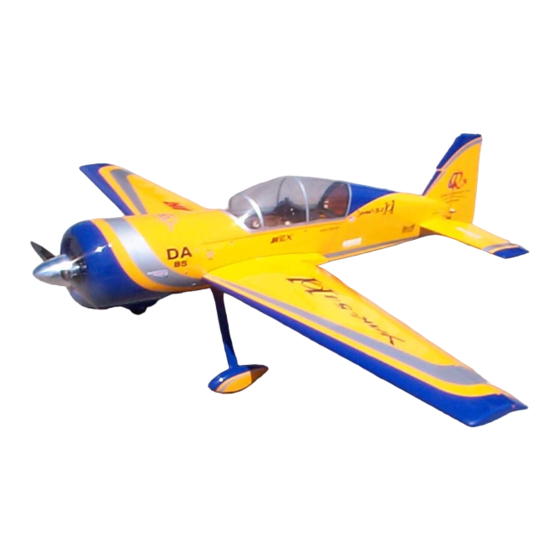
Semi Scale Yak-54, ARF 101"
Specifications
Wingspan:
Length Including Spinner:
Wing Area:
Weight (RTF):
Recommended Engines:
Gas
ASSEMBLY MANUAL
101 in
91 in
1,960 sq in
24.5-25.5 lb
80-85cc
Advertisement

Related Manuals for QuiQue's Aircraft Semi Scale Yak-54


Summary of Contents for QuiQue's Aircraft Semi Scale Yak-54
- Page 1 Semi Scale Yak-54, ARF 101” ASSEMBLY MANUAL Specifications Wingspan: 101 in Length Including Spinner: 91 in Wing Area: 1,960 sq in Weight (RTF): 24.5-25.5 lb Recommended Engines: 80-85cc...
- Page 2 Quique’s Aircraft Company 3410 Saint Paris Pike Springfield, OH 45504 Phone: (937) 629-0339 Fax: (937) 629-0335 Email: qqaircraft@gmail.com Website:www.QQAircraft.com Online-Support:http://www.rcuniverse.com/forum/forumid_437/tt.htm Quique and I want to express our thanks to you for choosing our 101” Yak-54. We think that you will enjoy one of the best flying model aerobatic airplanes available.
- Page 3 Covering Colors Ultra-cote covering used on this 101” Yak-54 can be purchased from Horizon Hobbies Website. The codes are as follows: Midnight Blue Hanu885 Silver Hanu881 White Hanu870 Dark Yellow Hanu889 Going Over the Covering Before beginning the assembly of your Yak-54, remove each part from its bag for inspection.
- Page 4 Hardware Supplied Pull/Pull Rudder Wing pins/clips aileron push rods Tail Wheel Canopy hardware Elevator Titanium rods & ball links pins Fuel Tank Cowl hardware Optional Dubro Hardware to complete your Assembly: Wheels and Axles Control Horn System...
- Page 5 Additional Required Tools and Adhesives • Covering/Trim iron • Xacto knife, #11 blade • Pacer hinge glue (PT-55) • 5,30-minute epoxy • Lithium grease • Acetone/Alcohol swabs • Pencil and Marker • Ruler • Drill • Drill bit 1/16”,1/8”, ¼”, 3/16”, #33, #25, #54 •...
- Page 6 All Other Parts Required to Complete the Aircraft • DA-85 or similar engine • (7) JR 8711 or similar Digital servo • (1) JR 4721 or similar analog servo • (4) 1.5” and (2) 1.25” single side Aluminum servo arms and (1) 3” double side aluminum servo arm for all control surfaces.
- Page 7 Servo Selection The servos used for the control surfaces of this Yak-54 are as follows: Ailerons (4), JR 8711 Elevator (2), JR 8711 Rudder (1), JR 8711 Throttle, any standard analog servo Make sure you use same or equivalent torque servos that are digital. Please do not risk your plane by using low torque or analog servos.
- Page 8 Preparing the Fuselage Required Tools and Adhesive • Xacto Knife, #11 Blade • Sealing Iron • Fine line Marker • Medium CA Preparing Fuselage FIG 1 In this step, we are going to remove covering from the Fuselage which will allow access for different components in coming steps.
- Page 9 Preparation and Installation of Hinges Figure 1 Required Tools and Adhesive • Xacto Knife, #11 Blade • Sealing Iron • Paper Towels • Pacer Hinge Glue (PT-55) Prepare Hinge Slots Hinge Slots are installed in your model. The Hinges have been placed into the slots from the factory, they have not been glued in place yet.
- Page 10 Wing and Stab Anti-Rotation Pin Installation Required Tools FIG 1 • Epoxy and Thin CA • Sand Paper • Acetone or Alcohol • Micro-balloons 1. Prepare the C/F anti-rotation pins by using coarse sandpaper and rough up the end of the pin where it will be inserted in the second rib in the H.Stab.
- Page 11 FIG 5 5. After the C/A has hardened, make a fillet of 15 minute epoxy and micro balloons and apply on the inside of the root rib. I used a small length of 3/16” wooden dowel to apply the epoxy-micro balloon mix. FIG 4 and 5 6.
- Page 12 Aileron Horn Installation Required Tools and Adhesive • Xacto knife, #11 Blade • 5-10 minute epoxy • Alcohol Swab/Alcohol and paper towel • Sealing Iron • Ruler • Blue Loctite • Pliers The Optional Du-bro package that we offer will have everything you need to complete the following steps, otherwise please use your alternative.
- Page 13 Wing Servo Installation 1. Now install the aileron servos so FIG 4 that output shaft is towards the leading edge of the wing. 2. Plug a 24" servo extension onto the outboard servo. Either tie the servo leads together, using a commercially available connector, or use unwaxed dental floss to secure the extensions to prevent them from coming loose during flight.
- Page 14 Elevator Horn Installation Required Tools and Adhesive FIG 1 • Xacto knife, #11 Blade • 5-10 minute epoxy • Alcohol Swab/Alcohol and paper towel • Sealing Iron • Ruler • Blue Loctite • Pliers The Optional Du-bro package that we offer will have everything you need to complete the following steps, otherwise please use your alternative.
- Page 15 Elevator Servo Installation We recommend using one JR 8711 servo for each Elevator half along with the 1.25” Aluminum servo arms and Du-bro Control Horn Hardware. 1. Install servo using four screws supplied, exit servo lead from root end of FIG 4 Stabilizer.
- Page 16 Rudder Horn, Servo and Pull/Pull Installation Required Tools FIG 1 • Xacto knife, #11 Blade • Sealing Iron • Ruler • Needle Nose Pliers • Epoxy • Sand Paper The Optional Du-bro package that we offer will have everything you need to complete the following steps, otherwise please use your alternative.
- Page 17 Landing Gear Installation Required Tools FIG 1 • Drill, 3/16”(4.5mm), 5/16”, 1/8” drill bit • Axles Dubro Cat No.249 • 4” Threaded light wheel Cat No. 400TL • Dremel with small sanding drum Landing Gear Installation 1. Landing gear comes drilled and ready to install but you still need to drill the holes for axles and wheel pants.
- Page 18 Install Tail Wheel Gear 1. Gear comes assembled. Remove all set screws and add blue loctite to each set screws and re-assemble. Mount tail wheel gear to fuselage using the three bolts provided in your kit. 2. Drill bottom of rudder to accept ball link. Sand ball link shank then glue into rudder.
- Page 19 Engine Installation Required Tools FIG 1 • 4- ¼”x1” bolts • 4- ¼” blind nuts • 1/16, 5/16 drill bits and Drill • Dremel and sanding drum DA-85 Engine Installation 1. Using 5/16 drill bit, drill four engine mount holes located on firewall.
- Page 20 Tuned Pipe and Header Installation Required Tools • FIG 1 Du-Bro brass Nipple #241 • Wire cutters • Red Silicone • Pliers • Dremel with cut off wheel Tuned Pipe and Header Installation 1. If you do not plan to use smoke tube, you will need to remove some of this tubing before pipe can fit into fuselage.
- Page 21 Engine Cowling Installation • Masking Tape Lower Engine Box Gussets Cowling Mount • Fine Point Marker Parts A and B • Straight Edge Ruler • 1/8” , 3/16” Drill Bits and Drill • • Epoxy • Dremel and sanding drum •...
- Page 22 FIG 6 6. Measure the center of each tab and drill. Install blind nuts using a C clamp to seat blind nuts in place. FIG 6 7. Locate clear plastic sheets that came in your model. These sheets will be used to help transfer blind nut locations to the out side of cowling.
- Page 23 Canopy Installation • C Clamp • Clear Silicone • FIG 1 Clear Packing Tape • White lithium Grease • Epoxy • Drill and bits 1. Set canopy onto fuselage, drill through fuselage into each canopy tab. FIG 1 2. Remove canopy re-drill each hole to the proper size of the blind nut.
- Page 24 Fuel Tank Installation FIG 1 • 4’ tygon fuel Line • Floral type wire or clamps • Velcro wrap • 5/16 drill bit • Fuel line tee • Double sided tape • 3/32” Balsa sheet • Assemble fuel tank according to manufactures directions. 1.
- Page 25 Radio Gear Installation Required Tools • FIG 1 Velcro tape • ½” Foam rubber • Radio Installation 1. After you have plugged servos into Rx, secure Rx to 1/8” plywood tray using Velcro straps. Place foam between Rx and plywood for added protection. FIG 1 2.
- Page 26 Balancing Model Perhaps one of the most important things that you need to check before you fly your plane is your model C.G. Correctly balancing an aerobatic model is critical to its performance and flight characteristics. An unbalanced model can be very hard to control. Please make sure that you carefully check the C.G of your plane before you attempt to fly it.
- Page 27 Control Throws Below picture shows you how to measure from center of wing trailing edge to center of aileron trailing edge. Exact number of low rate or high rate is not depicted! Aileron Throws Low Rate (Expo 65%) High Rate (Expo 70%) 3 3/8”Up 3 3/4”...
- Page 28 Elevator Throws Low Rate (Expo 45%) High Rate (Expo 80%) 7/8” Up 3 3/4”-3 7/8” Up 7/8” Down 3 3/4”-3 7/8” Down FIG 2...
- Page 29 Rudder Throws Low Rate (Expo 35%) High Rate (Expo 45%) 2 5/8” Right 5” Right 2 5/8” Left 5” Left FIG 3...
- Page 30 Preflight at the Field Range Test Your Radio Make sure you range check your radio before you attempt to fly your plane. Range check your radio without engine running and your antenna fully collapsed in case of JR 10X remove the antenna and range check with no antenna installed.
Need help?
Do you have a question about the Semi Scale Yak-54 and is the answer not in the manual?
Questions and answers