
Related Manuals for KTM 1190 RC8


Summary of Contents for KTM 1190 RC8
- Page 1 OWNER'S MANUAL 2009 1190 RC8 EU/UK 1190 RC8 AUS 1190 RC8 FR 1190 RC8 JP ART. NO. 3211373en...
- Page 3 KTM accepts no liability for delivery options, deviations from illustrations and descriptions, as well as misprints and other errors.
- Page 4 Reproduction, even in part, is permitted only with the express written permission of the copyright owner. ISO 9001(12 100 6061) According to the international quality management standard ISO 9001, KTM uses quality assurance processes that lead to the maximum possible quality of the products.
-
Page 5: Table Of Contents
CONTENTS Odometer menu ODO/Trip 1 ..........33 CONTENTS MEANS OF REPRESENTATION ..........7 Odometer menu ODO/Trip 2 ..........34 IMPORTANT NOTES ............... 8 FUELDISTANCE menu ............35 VIEW OF VEHICLE..............12 FUELRANGE menu............36 View of vehicle, front left side..........12 DISTANCE TO Next Service menu ........ - Page 6 Setting the fuel reserve display TRIPF RESET ..... 68 Important service tasks to be carried out by an authorized Setting the kilometers/miles SET KM/MILES ....... 69 KTM-RC8 workshop. (as additional job) ......95 Setting the temperature unit SET °C/°F ......70 MAINTENANCE WORK ON CHASSIS AND ENGINE....96 Switching the external temperature display on/off ....
- Page 7 CONTENTS Adjusting shift lever............116 Removing the passenger seat........... 147 Adjusting the footbrake pedal stub ........120 Mounting the passenger seat ........... 147 Adjusting the footbrake pedal .......... 121 Mounting the helmet lock on the vehicle......148 Checking for chain dirt............ 121 Removing the battery ..........
- Page 8 CONTENTS Installing the oil filter ..........192 Filling up with engine oil ..........192 Adding engine oil ............194 TROUBLESHOOTING............196 IMMOBILIZER FLASH CODE ..........199 ENGINE CONTROL FLASH CODE......... 201 CLEANING................. 206 Cleaning motorcycle ............206 CONSERVATION FOR WINTER OPERATION ......208 Conservation for winter operation ........
-
Page 9: Means Of Representation
All jobs marked with this symbol require specialist knowledge and technical understanding. In the interests of your own safety, have these jobs done in an authorized KTM-RC8 workshop! There, your motorcycle will be handled opti- mally by specially trained experts with the necessary special tools. -
Page 10: Important Notes
IMPORTANT NOTES Use definition KTM sport motorcycles are designed and constructed to meet the normal demands of regular road and race track operation, but not for use on dirt roads. Info The motorcycle is authorized for public road traffic in the homologous version only. - Page 11 IMPORTANT NOTES You will find the current KTM PowerParts for your vehicle on the KTM website. International KTM Website: http://www.ktm.com Work rules During assembly, non-reusable parts (e.g. self-locking screws and nuts, seals and seal rings, O-rings, pins, lock washers) must be replaced by new parts.
- Page 12 IMPORTANT NOTES flicts. To ensure the future of motorcycle sport, make sure you use the motorcycle legally, demonstrate a consciousness for the environ- ment, and respect the rights of others. Notes/warnings Pay close attention to the notes/warning. Info Various information and warning labels are affixed to the vehicle. Do not remove information/warning labels. If they are missing, you or others may not recognize dangers and may therefore be injured.
- Page 13 IMPORTANT NOTES – The owner's manual is an important component of the motorcycle and should be passed on to the new owner if the bike is sold.
-
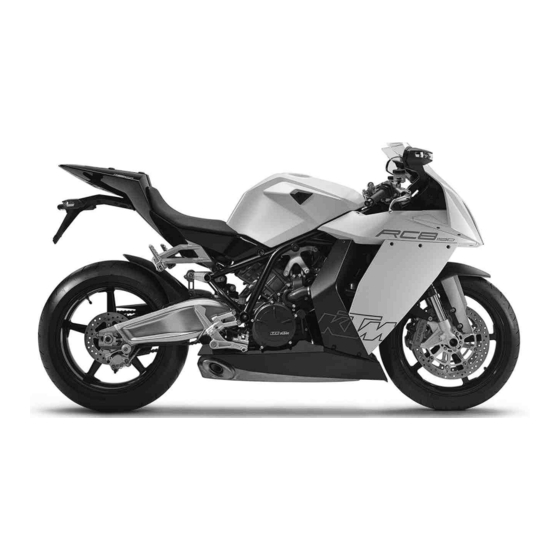
Page 14: View Of Vehicle
VIEW OF VEHICLE View of vehicle, front left side 700243-10... - Page 15 VIEW OF VEHICLE Clutch lever Light switch, headlight flasher switch, indicator switch, horn button Filler cap Seat Seat lock Oil dipstick Side stand Shift lever Passenger footrests...
-
Page 16: View Of Vehicle, Rear Right Side
VIEW OF VEHICLE View of vehicle, rear right side 700242-10... - Page 17 VIEW OF VEHICLE Passenger seat Supporting strap Rear mirror Combination instrument Emergency OFF switch, electric starter button Hand brake lever Chassis number, type label Rear brake caliper Foot brake pedal Engine number Brake calipers, front...
-
Page 18: Location Of Serial Numbers
LOCATION OF SERIAL NUMBERS Chassis number/type label The chassis number is stamped on the frame behind the steering head on the right. The type label is on the frame above the chassis number. 700231-01 Key number The key number Code number can be found on the KEYCODECARD. -
Page 19: Engine Number
LOCATION OF SERIAL NUMBERS Engine number The engine number is stamped on the right side of the engine. 700223-01 Fork part number The fork part number is stamped on the inner side of the fork stub. 700224-01... -
Page 20: Shock Absorber Part Number
LOCATION OF SERIAL NUMBERS Shock absorber part number The shock absorber part number is stamped on the upper part of the shock absorber above the adjusting ring towards the rear. 700225-01 Steering damper part number The steering damper part number is stamped on the top of the steering damper. -
Page 21: Operating Elements
OPERATING ELEMENTS Clutch lever The clutch lever is fitted on the left side of the handlebar. The clutch is hydraulic and self-adjusting. 700227-01 Hand brake lever The hand brake lever is fitted on the right side of the handlebar. ... -
Page 22: Light Switch
OPERATING ELEMENTS Light switch The light switch is fitted on the left side of the handlebar. Possible states Low beam on – Light switch is turned downwards. In this position, the low beam and tail light are switched on. High beam on –... -
Page 23: Flasher Switch
OPERATING ELEMENTS Flasher switch The flasher switch is fitted on the left side of the handlebar. Possible states Flasher light off Flasher light, left, on – Flasher switch pressed to the right. The flasher switch returns automatically to the central position after use. Flasher light, right, on –... -
Page 24: Ignition/Steering Lock
OPERATING ELEMENTS Ignition/steering lock The ignition/steering lock is located in front of the upper triple clamp. Possible states Ignition off – In this position, the ignition circuit is interrupted, a running engine stops, and a non-running engine will not start. The black ignition key can be removed. -
Page 25: Electric Starter Button
OPERATING ELEMENTS Electric starter button The electric starter button is fitted on the right side of the handlebar. Possible states • Electric starter button in neutral position pressed – In this position, the electric starter is operated. • Electric starter button 700229-12... -
Page 26: Combination Instrument - Overview
OPERATING ELEMENTS Combination instrument - overview 5.10 Display ( p. 27) Function buttons Indicator lamps ( p. 29) Info display ( p. 28) 400580-10... -
Page 27: Combination Instrument - Function Buttons On Handlebar
OPERATING ELEMENTS Combination instrument - function buttons on handlebar 5.11 The MODE button is fitted on the handlebar, front left. The LAP button is fitted on the handlebar, rear left. MODE button Changes to the next item on the info display in ROAD mode and in RACE mode. LAP button Changes to the next item in the info display in ROAD mode. -
Page 28: Combination Instrument - Activation And Test
The speed display counts from 0 to 300 and back. The remaining display segments outside the info display light up briefly. The KTM logo appears in the info display. In ROAD mode, the info display switches to ODO, Trip 1, Time 1, Avs 1 mode. -
Page 29: Display
OPERATING ELEMENTS Display 5.13 The tachometer displays the engine speed in revolutions per minute (RPM). The red marking marks the over-rev (excessive speed) range of the engine. The speed is displayed in kilometers per hour km/h or in miles per hour Mph. ... -
Page 30: Info Display
OPERATING ELEMENTS Info display 5.14 The info display has two menus. Menu 1 is ROAD mode (standard) for riding on public roads. Menu 2 is RACE mode for riding on race courses. It allows riders to time laps themselves. If the general warning lamp lights up, the corresponding message is shown periodically in the info display. -
Page 31: Indicator Lamps
OPERATING ELEMENTS Indicator lamps 5.15 Possible states The flasher indicator lamp flashes green in same rhythm as the flasher. – The flasher is switched on. The oil indicator lamp lights up red – The oil pressure is too low. The shift warning lights up/flashes red – The set shift speed is reached. The idling speed indicator lamp lights up green –... -
Page 32: Notes/Warnings On The Combination Instrument
OPERATING ELEMENTS Notes/warnings on the combination instrument 5.16 LOW FUEL appears on the info display if the minimum range falls below the specified value. Distance 20 km (12.4 mi) 400476-01 LOW BATTERY appears on the info display if the battery voltage falls below the specified value. - Page 33 OPERATING ELEMENTS SERVICE IN xxx KM(MPH) appears on the info display if the distance to the next service falls below the specified value. Distance 500 km (310.7 mi) 400472-01 HIGH TEMP appears on the info display if the coolant temperature rises above the specified value.
- Page 34 OPERATING ELEMENTS REAR SENSOR appears on the info display if the coolant temperature sensor of the rear cylin- der is defective. 400470-01 SENSOR ERROR appears on the info display if the coolant temperature between the coolant temperature sensors of the front and rear cylinders differs by more than the specified value. Coolant temperature 10 °C (50 °F) 400468-01...
-
Page 35: Odometer Menu Odo/Trip 1
OPERATING ELEMENTS Odometer menu ODO/Trip 1 5.17 Condition • The ignition is on. • ROAD mode – Press the MODE button briefly and repeatedly until ODO appears at the top left of the info display. ODO shows the total distance covered. Trip 1 shows the distance covered since the last reset. -
Page 36: Odometer Menu Odo/Trip 2
OPERATING ELEMENTS Odometer menu ODO/Trip 2 5.18 Condition • The ignition is on. • ROAD mode – Press the MODE button briefly and repeatedly until ODO appears at the top left of the info display. ODO shows the total distance covered. Trip 2 shows the distance covered since the last reset. -
Page 37: Fueldistance Menu
OPERATING ELEMENTS FUELDISTANCE menu 5.19 Condition • The ignition is on. • ROAD mode – Press the MODE button briefly and repeatedly until FUELDISTANCE appears at the top of the info display. TripFuel shows the distance covered since the fuel reserve level was reached. Info This is displayed only after you reach the fuel reserve level. -
Page 38: Fuelrange Menu
OPERATING ELEMENTS FUELRANGE menu 5.20 Condition • The ignition is on. • ROAD mode – Press the MODE button briefly and repeatedly until FUELRANGE appears at the top of the info display. TripFuel shows the distance covered since the fuel reserve level was reached. Info This is displayed only after you reach the fuel reserve level. -
Page 39: Distance To Next Service Menu
OPERATING ELEMENTS DISTANCE TO Next Service menu 5.21 Condition • The ignition is on. • The motorcycle is stationary. • ROAD mode – Press the MODE button briefly and repeatedly until DISTANCE TO Next Service appears in the info display. DISTANCE TO Next Service shows the distance before the next service is necessary. -
Page 40: Lapstogo Menu
OPERATING ELEMENTS LAPSTOGO menu 5.22 Condition • The ignition is on. • RACE mode – Press the MODE button briefly and repeatedly until LAPSTOGO appears at the top left of the info display. LAPSTOGO shows the number of remaining laps. If an R appears after LAPSTOGO, the stopwatch is running in the background. -
Page 41: Topspeed Menu
OPERATING ELEMENTS TOPSPEED menu 5.23 Condition • The ignition is on. • RACE mode – Press the MODE button briefly and repeatedly until TOPSPEED appears at the top left of the info display. If an R appears after TOPSPEED, the stopwatch is running in the background. If a P appears after TOPSPEED, the stopwatch is not running in the background. -
Page 42: Lap/Bestlap/Lastlap Menu
OPERATING ELEMENTS LAP/BESTLAP/LastLap menu 5.24 Condition • The ignition is on. • The motorcycle is stationary. RACE mode • – Press the MODE button briefly and repeatedly until LAP/BESTLAP/LastLap appears in the info display. LAP shows the selected lap. BESTLAP shows the number of the lap with the best lap time. LastLap shows the time of the lap behind LAP. -
Page 43: Lap/Bestlap/Topspeed Menu
OPERATING ELEMENTS LAP/BESTLAP/TopSpeed menu 5.25 Condition • The ignition is on. • The motorcycle is stationary. RACE mode • – Press the MODE button briefly and repeatedly until LAP/BESTLAP/TopSpeed appears in the info display. LAP shows the selected lap. BESTLAP shows the lap in which the highest maximum speed was reached. TopSpeed shows maximum speed of the lap behind LAP. -
Page 44: Total Distance Menu In Race Mode Raceodo
OPERATING ELEMENTS Total distance menu in Race mode RACEODO 5.26 Condition • The ignition is on. • The motorcycle is stationary. • RACE mode – Press the MODE button briefly and repeatedly until RACEODO appears at the top of the info display. -
Page 45: Set-Up Menu
OPERATING ELEMENTS SET‑UP menu 5.27 Condition • The ignition is on. • The motorcycle is stationary. – Press the button and the button for 3 - 5 seconds. On the CHANGE MODE menu, you can select between ROAD and RACE mode. You can set the clock on the SET CLOCK menu. -
Page 46: Change Mode Menu
OPERATING ELEMENTS CHANGE MODE menu 5.28 Condition • The ignition is on. • The motorcycle is stationary. – Press the button and the button for 3 - 5 seconds. – Press the MODE button briefly. On the CHANGE MODE menu, you can select between ROAD and RACE mode. Press the button Changes the menu Press the button... -
Page 47: Set Clock Menu
OPERATING ELEMENTS SET CLOCK menu 5.29 Condition • The ignition is on. • The motorcycle is stationary. – Press the button and the button for 3 - 5 seconds. – Press the button once until the symbol is on SET CLOCK in the info display. –... -
Page 48: Settings Menu
On the TRIP F RESET menu, you can set the reaction time of the fuel reserve display to changes of the fuel level. Only a KTM-RC8 workshop can make changes on the S.LEARN TPMS menu. On the BACK… menu, you can switch back to the SET‑UP menu. -
Page 49: Shift Rpms Menu
OPERATING ELEMENTS SHIFT RPMS menu 5.31 Condition • The ignition is on. • The motorcycle is stationary. – Press the button and the button for 3 - 5 seconds. – Press the button twice until the symbol is on SETTINGS in the info display. –... -
Page 50: Lap Menu, Lap Blank T Button
OPERATING ELEMENTS LAP menu, LAP BLANK T button 5.32 Condition • The ignition is on. • The motorcycle is stationary. – Press the button and the button for 3 - 5 seconds. – Press the button twice until the symbol is on SETTINGS in the info display. -
Page 51: Set Num Laps Menu
OPERATING ELEMENTS SET NUM LAPS menu 5.33 Condition • The ignition is on. • The motorcycle is stationary. – Press the button and the button for 3 - 5 seconds. – Press the button twice until the symbol is on SETTINGS in the info display. –... -
Page 52: Trip F Reset Menu
OPERATING ELEMENTS TRIP F RESET menu 5.34 Condition • The ignition is on. • The motorcycle is stationary. – Press the button and the button for 3 - 5 seconds. – Press the button twice until the symbol is on SETTINGS in the info display. –... -
Page 53: Units Menu
OPERATING ELEMENTS UNITS menu 5.35 Condition • The ignition is on. • The motorcycle is stationary. – Press the button and the button for 3 - 5 seconds. – Press the button three times until the symbol is on UNITS in the info display. –... -
Page 54: Set Km/Miles Menu
OPERATING ELEMENTS SET KM/MILES menu 5.36 Condition • The ignition is on. • The motorcycle is stationary. – Press the button and the button for 3 - 5 seconds. – Press the button three times until the symbol is on UNITS in the info display. –... -
Page 55: Set °C/°F Menu
OPERATING ELEMENTS SET °C/°F menu 5.37 Condition • The ignition is on. • The motorcycle is stationary. – Press the button and the button for 3 - 5 seconds. – Press the button three times until the symbol is on UNITS in the info display. –... -
Page 56: Options Menu
OPERATING ELEMENTS OPTIONS menu 5.38 Condition • The ignition is on. • The motorcycle is stationary. – Press the button and the button for 3 - 5 seconds. – Press the button four times until the symbol is on OPTIONS in the info display. –... -
Page 57: Tpms Menu
OPERATING ELEMENTS TPMS menu 5.39 Condition • The ignition is on. • The motorcycle is stationary. – Press the button and the button for 3 - 5 seconds. – Press the button four times until the symbol is on OPTIONS in the info display. –... -
Page 58: Outertemp Menu
OPERATING ELEMENTS OUTERTEMP menu 5.40 Condition • The ignition is on. • The motorcycle is stationary. – Press the button and the button for 3 - 5 seconds. – Press the button four times until the symbol is on OPTIONS in the info display. –... - Page 59 OPERATING ELEMENTS Table of functions Display Press the button Press the button Press the button Press the MODE but- Press the MODE button and the button ton for 3 - 5 sec- briefly. 3 - 5 seconds. onds. Odometer menu No function No function The display...
- Page 60 OPERATING ELEMENTS Table of functions Display Press the button Press the button Press the button Press the MODE but- Press the MODE button and the button ton for 3 - 5 sec- briefly. 3 - 5 seconds. onds. LAP/BESTLAP/Top- The next lap is dis- The previous lap is The display All values in...
- Page 61 OPERATING ELEMENTS Table of functions Display Press the button Press the button Press the button Press the MODE but- Press the MODE button and the button ton for 3 - 5 sec- briefly. 3 - 5 seconds. onds. SET NUM LAPS increases the value decreases the value no function...
- Page 62 OPERATING ELEMENTS Table of conditions and activability Display Menu can be • The igni- • The igni- • The igni- • The igni- • The igni- activated tion is on. tion is on. tion is on. tion is on. tion is on. •...
-
Page 63: Displaying Lap Times
OPERATING ELEMENTS Table of conditions and activability Display Menu can be • The igni- • The igni- • The igni- • The igni- • The igni- activated tion is on. tion is on. tion is on. tion is on. tion is on. •... -
Page 64: Displaying Maximum Speed
OPERATING ELEMENTS – Press the MODE button briefly and repeatedly until LAP/BESTLAP/LastLap appears in the info display. LAP01 appears on the left of the info display. – Press the button The next lap is displayed. – Press the button The previous lap is displayed. –... -
Page 65: Setting Road Or Race Mode
OPERATING ELEMENTS Setting ROAD or RACE mode 5.43 Condition The ignition is on. The motorcycle is stationary. – Press the button and the button for 3 - 5 seconds. – Press the MODE button briefly. The mode set is shown in the info display. –... -
Page 66: Adjusting Shift Speed Rpm1/2
OPERATING ELEMENTS – Press the MODE button briefly. The settings are stored and the display changes to the SET‑UP menu. – Press the button briefly and repeatedly until the symbol is on EXIT SETUP in the info display. – Press the MODE button briefly. Adjusting shift speed RPM1/2 5.45 Condition... -
Page 67: Setting The Blank Time Of The Lap Button Lap Blank T
OPERATING ELEMENTS – Press the MODE button briefly. The engine speed after RPM2 flashes. Info RPM2 is the engine speed above which the shift warning light lights up con- stantly. If RPM1 = RPM2, the shift warning light lights up constantly when you reach the engine speed set. - Page 68 OPERATING ELEMENTS – Press the button and the button for 3 - 5 seconds. – Press the button twice until the symbol is on SETTINGS in the info display. – Press the MODE button briefly. – Press the button once until the symbol is on LAP BLANK T in the info display.
-
Page 69: Setting The Number Of Laps Set Num Laps
OPERATING ELEMENTS Setting the number of laps SET NUM LAPS 5.47 Condition The ignition is on. The motorcycle is stationary. – Press the button and the button for 3 - 5 seconds. – Press the button twice until the symbol is on SETTINGS in the info display. -
Page 70: Setting The Fuel Reserve Display Tripf Reset
OPERATING ELEMENTS Setting the fuel reserve display TRIPF RESET 5.48 Condition The ignition is on. The motorcycle is stationary. – Press the button and the button for 3 - 5 seconds. – Press the button twice until the symbol is on SETTINGS in the info display. –... -
Page 71: Setting The Kilometers/Miles Set Km/Miles
OPERATING ELEMENTS Setting the kilometers/miles SET KM/MILES 5.49 Info Making a country-specific setting. Condition The ignition is on. The motorcycle is stationary. – Press the button and the button for 3 - 5 seconds. – Press the button three times until the symbol is on UNITS in the info display. -
Page 72: Setting The Temperature Unit Set °C/°F
OPERATING ELEMENTS Setting the temperature unit SET °C/°F 5.50 Condition The ignition is on. The motorcycle is stationary. – Press the button and the button for 3 - 5 seconds. – Press the button three times until the symbol is on UNITS in the info display. –... - Page 73 OPERATING ELEMENTS – Press the button and the button for 3 - 5 seconds. – Press the button four times until the symbol is on OPTIONS in the info display. – Press the MODE button briefly. – Press the button once until the symbol is on OPTION OUTTEMP in the info display.
-
Page 74: Opening The Filler Cap
OPERATING ELEMENTS Opening the filler cap 5.52 – Lift the cover of the filler cap and insert the ignition key in the lock. – Turn the ignition key clockwise until the filler cap opens. – Open the filler cap. 700235-01... -
Page 75: Closing The Filler Cap
OPERATING ELEMENTS Closing the filler cap 5.53 – Close the filler cap. Push down the filler cap slightly until the lock closes. – Remove the ignition key and close the cover. 700236-01 Supporting strap 5.54 The supporting strap is provided for the passenger to hold on to. ... -
Page 76: Seat Lock
OPERATING ELEMENTS Seat lock 5.55 The seat lock is behind the seat. It can be locked with the ignition key. 700245-01 Tool set 5.56 The tool set is in the storage compartment under the seat. 700310-01... -
Page 77: Helmet Lock
OPERATING ELEMENTS Helmet lock 5.57 The steel cable in the tool set can be used to lock a helmet to the vehicle to prevent it from being stolen. Warning Danger of accidents Impairment of handling characteristics and vehicle operation by a fitted helmet lock or helmet. –... -
Page 78: Shift Lever
OPERATING ELEMENTS Shift lever 5.59 The shift lever is mounted on the left of the engine. 700239-01 The gear positions can be seen in the picture. The neutral or idle position is between the first and second gear. 700238-01... -
Page 79: Foot Brake Pedal
OPERATING ELEMENTS Foot brake pedal 5.60 The foot brake pedal is in front of the right footrest. The foot brake pedal operates the rear brake. 700237-01 Side stand 5.61 The side stand is coupled with the safety start system; see the riding instructions. ... -
Page 80: Tips On Putting Into Operation
The front and rear wheels must be fitted with tires with similar tread patterns to prevent loss of control over the vehicle. Warning Danger of accidents Uncontrollable handling characteristics due to non-approved and/or non-recommended tires/wheels. – Only tires/wheels approved by KTM and with the corresponding speed index should be used. Warning Danger of accidents Reduced road grip with new tires. –... -
Page 81: Running The Engine In
When using your vehicle, remember that others may feel disturbed by excessive noise. – Make sure that the pre-delivery inspection work has been carried out exclusively by an authorized KTM-RC8 workshop. You receive a delivery certificate and the service record at vehicle handover. -
Page 82: Loading The Vehicle
TIPS ON PUTTING INTO OPERATION – Avoid full-throttle operation! Loading the vehicle Warning Danger of accidents Unstable riding behavior. – Do not exceed the maximum permitted weight and axle loads. The overall weight consists of: motorcycle operational and with a full tank, driver and passenger with protective clothing and helmet, baggage. Warning Danger of accidents Unstable handling characteristics due to incorrect mounting of suitcase and/or tank rucksack. - Page 83 TIPS ON PUTTING INTO OPERATION Warning Danger of accidents Unstable handling characteristics due to slipped baggage. – Check the way your baggage is fixed regularly. – If you carry any baggage, make sure it is fixed firmly as close as possible to the center of the vehicle and ensure even weight distribu- tion between the front and rear wheels.
-
Page 84: Riding Instructions
RIDING INSTRUCTIONS Checks to be made before putting into operation Info During operation, the motorcycle must be in a technically perfect condition. In the interest of riding safety, you should get into the habit of making a general check of the motorcycle before every journey. –... -
Page 85: Starting
RIDING INSTRUCTIONS Starting Danger Danger of poisoning Exhaust gases are poisonous and can result in unconsciousness and/or death. – When running the engine, always make sure there is sufficient ventilation, and do not start or run the engine in a closed space without an effective exhaust extraction system. -
Page 86: Starting Up
RIDING INSTRUCTIONS – Press the emergency OFF switch into the position – Switch on the ignition by turning the black ignition key to the position When you switch on the ignition, you hear the fuel pump working for about 2 sec- onds. -
Page 87: Shifting, Riding
RIDING INSTRUCTIONS Shifting, riding Warning Danger of accidents An abrupt load alterations can cause the vehicle to get out of control. – Avoid abrupt load alterations and sudden braking actions, and adapt your speed to the road conditions. Warning Danger of accidents If you change down at high engine speed, the rear wheel can lock up. –... - Page 88 RIDING INSTRUCTIONS Warning Danger of accidents Reduced road grip with cold tires. – On every journey, take the first miles carefully at moderate speed until the tires reach operating temperature and optimal road grip is ensured. Warning Danger of accidents Reduced road grip with new tires. –...
- Page 89 Info If you hear unusual noises while riding, stop immediately, switch off the engine and contact an authorized KTM-RC8 workshop. – When conditions allow (incline, road situation, etc.), you can shift into a higher gear.
-
Page 90: Braking
Clean or dry dirty or wet brakes by riding and braking gently. Warning Danger of accidents Reduced braking effect caused by spongy pressure point of front or rear brake. – Have the brake system checked in an authorized KTM-RC8 workshop before continuing your journey. Warning Danger of accidents Brake system failure. –... -
Page 91: Stopping, Parking
RIDING INSTRUCTIONS Warning Danger of accidents Delayed brake action on salted roads. – Salt can be deposited on the brake discs. To achieve the normal braking effect, the brake discs must first be cleaned by brak- ing. – When braking, first throttle back and then apply the front and rear brakes at the same time. –... -
Page 92: Refueling
RIDING INSTRUCTIONS – Do not place the vehicle where there are flammable or explosive substances. Do not place objects over the vehicle while it is still warm from being run. Always let the vehicle cool first. Note Material damage Damage and destruction of components by excessive load. –... - Page 93 RIDING INSTRUCTIONS Warning Danger of poisoning Fuel is poisonous and a health hazard. – Avoid contact between fuel and skin, eyes and clothing. Do not inhale fuel vapors. If fuel gets into your eyes, rinse immediately with water and contact a doctor. Wash affected skin areas immediately with soap and water. If fuel is swallowed, contact a doc- tor immediately.
-
Page 94: Service Schedule
SERVICE SCHEDULE Important service tasks to be carried out by an authorized KTM-RC8 workshop. K10N K75A K150A Engine • • • • • Change the engine oil and filter, clean the oil screen. p. 187) • Check the valve clearance. - Page 95 SERVICE SCHEDULE K10N K75A K150A Attachments Check the exhaust system for leaks and correct fitting and check that • • • the exhaust holders are tight. Check bowden cables for damage, smooth operation, kink-free routing • • • • • and adjustment.
- Page 96 SERVICE SCHEDULE K10N K75A K150A Chassis Bleed fork legs. ( p. 101) • • • • • Check the steering head bearing and adjust if necessary. • • • • • • Check the swingarm bearing. • • Check deflector. •...
-
Page 97: Important Service Tasks To Be Carried Out By An Authorized Ktm-Rc8 Workshop. (As Additional Job)
SERVICE SCHEDULE Important service tasks to be carried out by an authorized KTM-RC8 workshop. (as additional job) K150A K300A • Completely service fork. • Completely service shock absorber. • • • Clean and grease the steering head bearing and sealing elements. -
Page 98: Maintenance Work On Chassis And Engine
MAINTENANCE WORK ON CHASSIS AND ENGINE Jacking up motorcycle front Note Danger of damage The parked vehicle can roll away or fall over. – Always place the vehicle on a firm and even surface. – Jack up the motorcycle rear end. ( p. -
Page 99: Jacking Up Motorcycle Rear
MAINTENANCE WORK ON CHASSIS AND ENGINE Jacking up motorcycle rear Note Danger of damage The parked vehicle can roll away or fall over. – Always place the vehicle on a firm and even surface. – Insert the work stand adapter in the rear of the work stand. Work stand adapter (61029055120) Work stand rear (61029055100) –... -
Page 100: Fork/Shock Absorber
MAINTENANCE WORK ON CHASSIS AND ENGINE Fork/shock absorber The fork and the shock absorber offer many options of adapting the chassis to your riding style and the payload. Info To help you adapt the vehicle, we have summarized our findings in Table . -
Page 101: Adjusting The Rebound Damping Of The Fork
MAINTENANCE WORK ON CHASSIS AND ENGINE – Turn adjusting screws clockwise until they stop. Info The adjusting screws are located at the bottom end of the fork legs. Make the same adjustment on both fork legs. – Turn back counterclockwise by the number of clicks corresponding to the fork type. Guideline Compression damping 700253-01... -
Page 102: Adjusting The Spring Preload Of The Fork
MAINTENANCE WORK ON CHASSIS AND ENGINE – Turn adjusting screws clockwise until they stop. Info The adjusting screws are located at the top end of the fork legs. Make the same adjustment on both fork legs. – Turn back counterclockwise by the number of clicks corresponding to the fork type. Guideline Rebound damping Comfort... -
Page 103: Bleeding Fork Legs
MAINTENANCE WORK ON CHASSIS AND ENGINE – Turn adjusting spindles clockwise until they stop. Info The adjusting spindles are located at the top end of the fork legs. Make the same adjustment on both fork legs. – Turn back counterclockwise by the number of turns corresponding to the fork type. Guideline Spring preload - Preload Adjuster Comfort... -
Page 104: Compression Damping Of The Shock Absorber
MAINTENANCE WORK ON CHASSIS AND ENGINE – Remove bleeder screws briefly. Any excess pressure escapes from the interior of the fork. – Mount and tighten bleeder screws. Info Perform this action on both fork legs. 700259-01 Compression damping of the shock absorber 9.10 The shock absorber can coordinate the compression damping separately in the low ... -
Page 105: Adjusting The High-Speed Compression Damping Of The Shock Absorber
MAINTENANCE WORK ON CHASSIS AND ENGINE Info The low-speed setting can be seen during the slow to normal compression of the shock absorber. – Turn adjusting screw clockwise with a screwdriver up to the last perceptible click. Info Do not loosen nut ... -
Page 106: Adjusting The Rebound Damping Of The Shock Absorber
MAINTENANCE WORK ON CHASSIS AND ENGINE Info The high-speed setting can be seen during the fast compression of the shock absorber. – Turn adjusting screw clockwise with an open-ended spanner until it stops. Info Do not loosen nut –... -
Page 107: Adjusting The Spring Preload Of The Shock Absorber
MAINTENANCE WORK ON CHASSIS AND ENGINE – Turn adjusting screw clockwise up to the last perceptible click. – Turn back counterclockwise by the number of clicks corresponding to the shock absorber type. Guideline Rebound damping Comfort 15 clicks Standard 10 clicks Sport 5 clicks... - Page 108 MAINTENANCE WORK ON CHASSIS AND ENGINE – Take the weight off the rear wheel and swingarm. Info The spring preload can be adjusted correctly only if the rear wheel and the swingarm are fully relieved of weight. – Loosen screw two turns, but do not remove.
-
Page 109: Steering Damper
MAINTENANCE WORK ON CHASSIS AND ENGINE – Tighten screw Guideline Remaining chassis screws 5 Nm (3.7 lbf ft) 700341-11 Steering damper 9.15 The steering damper suppresses shocks to the steering arising from acceleration on uneven ground at high speed or when the load is temporarily taken from the front wheel. The steering damper is adjusted to suit the manner of driving and the road conditions. - Page 110 MAINTENANCE WORK ON CHASSIS AND ENGINE – Turn the adjusting screw counterclockwise towards "–" as far as the last perceptible click. – Adjust the steering damper according to your riding style and the road conditions by turning the adjust screw clockwise towards "+". Guideline Steering damper adjustment range 1…...
-
Page 111: Vehicle Level
MAINTENANCE WORK ON CHASSIS AND ENGINE Vehicle level 9.17 Warning Danger of accidents Modifications to the chassis can seriously alter the vehicle's handling characteristics. – Following modifications, ride slowly at first to get the feel of the new handling characteristics. The vehicle level can be adjusted at the front by means of the fork leg clamp and at the rear by the eccentric shaft. -
Page 112: Adjusting Front Vehicle Level
MAINTENANCE WORK ON CHASSIS AND ENGINE Adjusting front vehicle level 9.18 Warning Danger of accidents Modifications to the chassis can seriously alter the vehicle's handling characteristics. – Following modifications, ride slowly at first to get the feel of the new handling characteristics. –... - Page 113 MAINTENANCE WORK ON CHASSIS AND ENGINE – Align the fork leg in the desired position by means of the fork rings. Guideline Upper triple clamp flush with upper edge 0 mm (0 in) of fork legs Upper triple clamp flush with 1st ring of 2.5 mm (0.098 in) fork legs Upper triple clamp flush with 2nd ring of...
-
Page 114: Adjusting The Vehicle Level At The Rear
MAINTENANCE WORK ON CHASSIS AND ENGINE – Repeat the adjustment on the other fork leg. Info The setting of the vehicle level via the fork legs must be identical on both fork legs. Adjusting the vehicle level at the rear 9.19 Warning Danger of accidents Modifications to the chassis can seriously alter the vehicle's handling characteristics. - Page 115 MAINTENANCE WORK ON CHASSIS AND ENGINE – Turn eccentric shaft to the desired position using the tool from the tool set. Guideline Standard Maximum adjustment range between 180° HIGH - LOW Open end wrench SW 38 (69012021000) Info 700332-01 The chassis height can be adjusted in both directions.
-
Page 116: Footrest Position
MAINTENANCE WORK ON CHASSIS AND ENGINE Footrest position 9.20 The adjustable footrest system enables an individual setting of the footrest height and an individual adjustment of the operating elements. The lower footrest position enables a more comfortable knee angle, the upper footrest posi- tion a sporting sitting position and more forward-leaning freedom for use in racing. - Page 117 MAINTENANCE WORK ON CHASSIS AND ENGINE – Position the footrest bracket with spacers and screws. Guideline Standard Lower position Info The adjustable footrest bracket enables a more comfortable lower footrest posi- tion or a sporting upper footrest position. 700308-01 –...
-
Page 118: Adjusting Shift Lever Stub
MAINTENANCE WORK ON CHASSIS AND ENGINE Adjusting shift lever stub 9.22 – Remove the screw with the shift lever stub. – Position the shift lever stub with the screw in one of the holes according to the desired lever length. Guideline Standard Central hole... - Page 119 MAINTENANCE WORK ON CHASSIS AND ENGINE – Remove screws and take off the shift rod. – The length of the shift rod can be adjusted by means of the screw thread. Guideline Shift rod 115… 130 mm (4.53… 5.12 in) –...
- Page 120 MAINTENANCE WORK ON CHASSIS AND ENGINE – The shift rod can be mounted both on the shift lever variably at an upper or lower posi- tion, and on the reverse gear change of the shift shaft in two different positions. Guideline Standard Shift lever: lower drill hole,...
- Page 121 MAINTENANCE WORK ON CHASSIS AND ENGINE – The position of the shift lever can be greatly varied, depending on the length of the shift rod and the drill holes selected. As seen from the footrest, there is either a high position of the shift lever or a low position of the shift lever ...
-
Page 122: Adjusting The Footbrake Pedal Stub
MAINTENANCE WORK ON CHASSIS AND ENGINE Adjusting the footbrake pedal stub 9.24 – Remove the screw with the footbrake pedal stub. – Position the footbrake pedal stub with the screw in one of the holes according to the desired lever length. -
Page 123: Adjusting The Footbrake Pedal
MAINTENANCE WORK ON CHASSIS AND ENGINE Adjusting the footbrake pedal 9.25 – Use the tool to press in the anti-rotation lock , then turn the piston rod Info The range of adjustment is limited. – Remove the tool. The spring tension on the anti-rotation lock is released and the hex nut is locked. -
Page 124: Cleaning The Chain
MAINTENANCE WORK ON CHASSIS AND ENGINE Cleaning the chain 9.27 Warning Danger of accidents Oil or grease on the tires reduces their grip. – Remove oil and grease with a suitable cleaning material. Warning Danger of accidents Reduced braking due to oil or grease on the brake discs. –... -
Page 125: Checking The Chain Tension
MAINTENANCE WORK ON CHASSIS AND ENGINE Checking the chain tension 9.28 Warning Danger of accidents Danger caused by incorrect chain tension. – If the chain tension is too high, the components of the secondary power train (chain, engine sprocket, rear sprocket, bearings in transmission and rear wheel) are under additional load. -
Page 126: Adjusting The Chain Tension
MAINTENANCE WORK ON CHASSIS AND ENGINE Adjusting the chain tension 9.29 Warning Danger of accidents Danger caused by incorrect chain tension. – If the chain tension is too high, the components of the secondary power train (chain, engine sprocket, rear sprocket, bearings in transmission and rear wheel) are under additional load. - Page 127 MAINTENANCE WORK ON CHASSIS AND ENGINE – Loosen nut – Loosen nuts – Adjust chain tension by turning the adjustment screws on the left and right. Guideline Chain tension 15… 20 mm (0.59… 0.79 in) Turn the adjusting screws on the left and right so that the markings on the left and ...
-
Page 128: Checking Rear Sprocket / Engine Sprocket For Wear
MAINTENANCE WORK ON CHASSIS AND ENGINE Checking rear sprocket / engine sprocket for wear 9.30 – Check the rear sprocket / engine sprocket for wear. » If the rear sprocket / engine sprocket are worn: – Change the rear sprocket / engine sprocket, chain and chain sliding guard. Info The rear sprocket, engine sprocket, chain and chain sliding guard should always be changed together. -
Page 129: Checking Chain Wear
Change the rear sprocket / engine sprocket, chain and chain sliding guard. Info New chains wear out faster on old, worn sprockets. For safety reasons, the chain has no chain joint. Always have the chain changed in an authorized KTM-RC8 workshop, where they have the nec- 700303-01 essary special tools. -
Page 130: Checking Chain Sliding Guard
Danger of accidents Reduced braking effect caused by worn brake discs. – Have worn brake discs replaced immediately in an authorized KTM-RC8 workshop. – Check the thickness of the brake disc in several places to see if it conforms to measure- ment ... -
Page 131: Checking The Rear Brake Disc
Danger of accidents Reduced braking effect caused by worn brake discs. – Have worn brake discs replaced immediately in an authorized KTM-RC8 workshop. – Check the thickness of the brake disc in several places to see if it conforms to measure- ment ... -
Page 132: Adjusting The Basic Position Of The Handbrake Lever
Have the brake system checked in an authorized KTM-RC8 workshop before continuing your journey. Warning Danger of accidents Reduced braking effect caused by old brake fluid. – Have the brake fluid of the front and rear brakes changed according to the service plan in an authorized KTM-RC8 workshop. -
Page 133: Topping Up Brake Fluid Of Front Brake
If brake fluid gets into your eyes, rinse thoroughly with water and contact a doctor immediately. Warning Danger of accidents Reduced braking effect caused by old brake fluid. – Have the brake fluid of the front and rear brakes changed according to the service plan in an authorized KTM-RC8 workshop. -
Page 134: Brake Linings
Clean up overflowed or spilt brake fluid immediately with water. 700262-01 Brake linings 9.38 The brake linings fitted by KTM have been tested over long periods and guarantee optimal braking characteristics. The type names of the brake linings are entered in the homologation documents. -
Page 135: Checking The Front Brake Linings
Brake linings available in accessories shops are often untested and unapproved for use on KTM vehicles. The structure and friction coefficient of the brake linings, and therefore the brake power, can vary considerably from the original KTM brake linings. If brake linings other than those supplied as originals are used, there is no guarantee that they correspond to the original homologation. -
Page 136: Checking Rear Brake Fluid Level
Have the brake system checked in an authorized KTM-RC8 workshop before continuing your journey. Warning Danger of accidents Reduced braking effect caused by old brake fluid. – Have the brake fluid of the front and rear brakes changed according to the service plan in an authorized KTM-RC8 workshop. – Stand the vehicle upright. –... - Page 137 Warning Danger of accidents Reduced braking effect caused by old brake fluid. – Have the brake fluid of the front and rear brakes changed according to the service plan in an authorized KTM-RC8 workshop. Warning Environmental hazard Problem materials cause environmental damage.
-
Page 138: Checking The Rear Brake Linings
9.42 Warning Danger of accidents Reduced braking caused by worn brake linings. – Have worn brake linings replaced immediately in an authorized KTM-RC8 workshop. Note Danger of accidents Reduced braking due to damaged brake discs. – If the brake linings are not changed in time, the steel brake lining carriers grind on the brake disc. The braking effect is greatly reduced and the brake discs are destroyed. - Page 139 MAINTENANCE WORK ON CHASSIS AND ENGINE – Remove the screws from both brake calipers. – Press back the brake linings with a light lateral tilting of the brake calipers on the brake disc. Pull the brake calipers carefully back from the brake discs and hang them to one side.
-
Page 140: Fitting Front Wheel
MAINTENANCE WORK ON CHASSIS AND ENGINE Fitting front wheel 9.44 Warning Danger of accidents Reduced braking due to oil or grease on the brake discs. – Always keep the brake discs free of oil and grease, and clean them with brake cleaner when necessary. –... -
Page 141: Removing Rear Wheel
MAINTENANCE WORK ON CHASSIS AND ENGINE – Pull the front brake and compress the fork powerfully a few times. The fork legs straighten. – Fully tighten screws Guideline Screw, fork stub 15 Nm (11.1 lbf ft) 700272-11 Removing rear wheel 9.45 –... -
Page 142: Installing The Rear Wheel
MAINTENANCE WORK ON CHASSIS AND ENGINE – Push the rear wheel forward as far as possible and take the chain off the rear sprocket. – Pull the rear wheel backward until brake caliper support hangs free between the brake disc and the wheel rim. Warning Danger of accidents Reduced braking effect caused by damaged brake discs. - Page 143 MAINTENANCE WORK ON CHASSIS AND ENGINE – Remove bushing and bushing . Clean and grease the roll surfaces of the bushing and the shaft seal rings. Long-life grease ( p. 229) – Fit the bushings. – Clean the thread of the wheel spindle and nut. –...
- Page 144 MAINTENANCE WORK ON CHASSIS AND ENGINE – Push the rear wheel forward as far as possible and place the chain on the rear sprocket. – Pull the rear wheel back and push in the wheel spindle. 700315-01 – Lay the chain adjuster on the tensioning screw.
-
Page 145: Checking Rear Hub Shock Absorbers
MAINTENANCE WORK ON CHASSIS AND ENGINE Checking rear hub shock absorbers 9.47 Info The engine power is transmitted by the rear sprocket to the rear wheel through 5 shock absorbers. They are subject to wear during operation. If the shock absorbers are not changed in time, the rear sprocket carrier and the rear hub are damaged. –... - Page 146 MAINTENANCE WORK ON CHASSIS AND ENGINE Warning Danger of accidents Uncontrollable handling characteristics due to non-approved and/or non-recommended tires/wheels. – Only tires/wheels approved by KTM and with the corresponding speed index should be used. Warning Danger of accidents Reduced road grip with new tires. –...
-
Page 147: Checking Tire Air Pressure
MAINTENANCE WORK ON CHASSIS AND ENGINE Checking tire air pressure 9.49 Info Low tire air pressure leads to abnormal wear and overheating of the tire. Correct tire air pressure ensures optimal riding comfort and maximum tire service life. – Remove dust cap. –... -
Page 148: Removing The Seat
MAINTENANCE WORK ON CHASSIS AND ENGINE Removing the seat 9.50 – Insert the ignition key in the seat lock and turn it clockwise. – Raise the rear of the seat, push it towards the rear, and remove it upwards. 700245-01 Fitting the seat 9.51... -
Page 149: Removing The Passenger Seat
MAINTENANCE WORK ON CHASSIS AND ENGINE Removing the passenger seat 9.52 – Remove the seat. ( p. 146) – Activate the release lever – Take off the passenger seat toward the top. 700246-01 Mounting the passenger seat 9.53 Warning Danger of accidents The passenger seat can come loose from the anchoring if it is not mounted correctly. -
Page 150: Mounting The Helmet Lock On The Vehicle
MAINTENANCE WORK ON CHASSIS AND ENGINE Mounting the helmet lock on the vehicle 9.54 Warning Danger of accidents Impairment of handling characteristics and vehicle operation by a fitted helmet lock or helmet. – Do not use the helmet lock for holding a helmet or other objects during the journey. Always remove the helmet lock before start- ing out. - Page 151 MAINTENANCE WORK ON CHASSIS AND ENGINE – Switch off all power consumers and switch off the engine. – Remove the seat. ( p. 146) – Disconnect the negative (minus) cable of the battery. 700276-10 – Remove the plus pole cover. –...
-
Page 152: Installing The Battery
MAINTENANCE WORK ON CHASSIS AND ENGINE – Remove screws – Removing the securing bracket – Pull battery up and out of the battery rack. Info Never operate the motorcycle with a discharged battery or without a battery. In both cases, electrical components and safety equipment can be damaged. - Page 153 MAINTENANCE WORK ON CHASSIS AND ENGINE – Mount and tighten screws Guideline Remaining chassis screws 10 Nm (7.4 lbf ft) – Reconnect the positive (plus) cable of the battery. – Position positive terminal cover. 700277-11 – Reconnect the negative (minus) cable of the battery.
-
Page 154: Recharging The Battery
MAINTENANCE WORK ON CHASSIS AND ENGINE Recharging the battery 9.57 Warning Risk of injury Battery acid and battery gases cause serious chemical burns. – Keep batteries out of the reach of children. – Wear suitable protective clothing and goggles. – Avoid contact with battery acid and battery gases. –... - Page 155 MAINTENANCE WORK ON CHASSIS AND ENGINE Info Even if there is no load on the battery, it loses power every day. The charge state and the type of charge are very important for the service life of the battery. Fast recharging with a high charge current shortens the battery's service life. If the charge current, the charge voltage and the charge time are exceeded, electrolyte escapes through the breathing holes.
-
Page 156: Changing The Main Fuse
MAINTENANCE WORK ON CHASSIS AND ENGINE – Connect the battery charger to the battery. Switch on the battery charger. Battery charger (58429074000) You can also use the battery charger to test rest potential and start potential of the bat- tery, and to test the generator. With this device, you cannot overcharge the battery. Info Never remove the lid ... - Page 157 Fit a new main fuse. Fuse (58011109130) ( p. 217) Info If the new fuse burns out after it is inserted, it is important that you contact an authorized KTM-RC8 workshop. – Attach the protection covers – Fit the seat. ( p.
-
Page 158: Changing The Fuses Of Individual Power Consumers
MAINTENANCE WORK ON CHASSIS AND ENGINE Changing the fuses of individual power consumers 9.59 Warning Fire hazard The electrical system can be overloaded by the use of incorrect fuses. – Use only fuses with the prescribed amperage. Never by-pass or repair fuses. Info The fuse box containing the fuses of individual power consumers is located under the seat. - Page 159 MAINTENANCE WORK ON CHASSIS AND ENGINE – Check the fuses. Info A defective fuse is shown by a burned-out fuse wire – Remove the defective fuse. Guideline Fuse 1 - 10A - ignition, combination instrument, immobilizer, alarm system (optional) 700282-01 Fuse 2 - 15A - high beam, low beam, parking light, tail light, license plate lamp Fuse 3 - 10A - horn, brake light...
-
Page 160: Changing The Low Beam Bulb
217) Info If the new fuse burns out after it is inserted, it is important that you contact an authorized KTM-RC8 workshop. Replace the spare fuse in the fuse box so that it is available if needed. – Close the fuse box cover. - Page 161 MAINTENANCE WORK ON CHASSIS AND ENGINE – Fold up the combination instrument. Pull the lug out of the rubber holder – Remove the rubber holder. 700293-01 – Release the latch – Remove the lamp cover 700294-01 –...
- Page 162 MAINTENANCE WORK ON CHASSIS AND ENGINE – Position the new headlight bulb in the headlight housing. Low beam / high beam (H7) ( p. 217) Info Insert the headlight bulb so that the lug is positioned in the cut-out. –...
-
Page 163: Changing The High Beam Lamp
MAINTENANCE WORK ON CHASSIS AND ENGINE – Position the rubber holder – Fold down the combination instrument. Position the lug in the rubber holder. 700293-11 Changing the high beam lamp 9.61 Note Damage to reflector Keep the glass of the bulb free of grease. –... - Page 164 MAINTENANCE WORK ON CHASSIS AND ENGINE – Remove screws . Remove cover. 700297-01 – Release the latch – Remove the lamp cover 700298-01...
- Page 165 MAINTENANCE WORK ON CHASSIS AND ENGINE – Disconnect plug-in connector – Push off the retaining clamp on both sides, squeeze and fold to the side. – Remove headlight bulb. – Position the new headlight bulb in the headlight housing. Low beam / high beam (H7) ( p.
- Page 166 MAINTENANCE WORK ON CHASSIS AND ENGINE – Position the lug of the lamp cover in the notch. Engage the latch. – Check lighting function. 400422-11 – Position cover. Info Check for correct positioning and freedom of movement of the brake lines. –...
-
Page 167: Changing The Parking Light Bulb
MAINTENANCE WORK ON CHASSIS AND ENGINE Changing the parking light bulb 9.62 Note Damage to reflector Keep the glass of the bulb free of grease. – Clean the glass bulb with a clean cloth before mounting. Any grease on the glass will evaporate by the heat and be deposited on the reflector. - Page 168 MAINTENANCE WORK ON CHASSIS AND ENGINE – Release the latch – Remove the lamp cover 700298-01 – Pull the parking light carefully out of the holder. – Remove the light bulb. – Position a new light bulb in the holder. Parking light (W2.1x9.5d) ( p.
- Page 169 MAINTENANCE WORK ON CHASSIS AND ENGINE – Position the lug of the lamp cover in the notch. Engage the latch. – Check lighting function. 400422-12 – Position cover. Info Check for correct positioning and freedom of movement of the brake lines. –...
-
Page 170: Checking Headlight Adjustment
MAINTENANCE WORK ON CHASSIS AND ENGINE Checking headlight adjustment 9.63 – On a light-colored wall behind a horizontal area, make a mark as high as the center of 0 0 A the low beam headlight. – Make another mark at a distance of under the first mark. -
Page 171: Activating/Deactivating Ignition Key
MAINTENANCE WORK ON CHASSIS AND ENGINE – Adjust the beam distance of the headlight by turning screw Guideline The boundary between light and dark must be exactly on the lower mark for a motor- cycle with a rider (mark is applied under: Checking headlight adjustment). Info Turn clockwise to increase the light range, turn counterclockwise to reduce the light range. - Page 172 MAINTENANCE WORK ON CHASSIS AND ENGINE – Switch on the ignition by turning the black ignition key to the position EFI warning lamp (MIL) lights up, switches off, and then starts to flash. The immobilizer indicator lamp lights up, switches off briefly, and switches on again.
- Page 173 MAINTENANCE WORK ON CHASSIS AND ENGINE – Switch on the ignition by turning the orange programming key to the position EFI warning lamp (MIL) lights up, switches off, and then starts to flash. The immobilizer indicator lamp lights up, switches off briefly, and flashes according to the number of functioning black ignition keys including the orange programming key.
-
Page 174: Cooling System
MAINTENANCE WORK ON CHASSIS AND ENGINE – To activate further ignition keys, repeat the last 4 steps with the respective ignition key. – Insert the orange programming key in the ignition lock. – Switch on the ignition by turning the orange programming key to the position EFI warning lamp (MIL) lights up, switches off, and then starts to flash. -
Page 175: Checking The Coolant Level
MAINTENANCE WORK ON CHASSIS AND ENGINE Cooling takes place by means of the air stream and a radiator fan , which is controlled by a thermoswitch. The lower the speed, the less the cooling effect. Dirty cooling fins also reduce the cooling effect. -
Page 176: Filling The Cooling System Compensating Tank
MAINTENANCE WORK ON CHASSIS AND ENGINE – Check the coolant level in the compensating tank. The coolant level must be between MIN and MAX. » If there is no coolant in the compensating tank: – Check the cooling system for leaks. Info Do not operate the motorcycle! –... - Page 177 This is the only way of ensuring that the cooling system is filled without air bubbles. Air in the cooling system can lead to engine fail- ure. – Have the coolant changed by an authorized KTM-RC8 workshop. – Check the coolant level. ( p.
-
Page 178: Adjusting Basic Position Of Clutch Lever
MAINTENANCE WORK ON CHASSIS AND ENGINE Adjusting basic position of clutch lever 9.69 – Adjust the basic setting of the clutch lever to your hand size by turning adjusting screw Info Turn the adjusting screw clockwise to increase the distance between the clutch lever and the handlebar. -
Page 179: Correcting Fluid Level Of Hydraulic Clutch
MAINTENANCE WORK ON CHASSIS AND ENGINE – Check the fluid level. The fluid level must be between the MIN and MAX markings. » If the fluid level does not meet specifications: – Correct the fluid level of the hydraulic clutch. ( p. -
Page 180: Adjusting The Gas Bowden Cable
Adjusting the gas Bowden cable 9.72 – Move the handlebar to the straight-ahead position. – Use the KTM diagnostics tool to set the throttle stepper motor to the neutral position. – Loosen counter nut – Adjust the gas Bowden cable with adjusting screw ... -
Page 181: Adjusting The Handlebar Height
MAINTENANCE WORK ON CHASSIS AND ENGINE Adjusting the handlebar height 9.74 Info The handlebar stub position must be identical on the left and right of the vehicle. Adjusting the high position of the handlebar stubs: – Loosen screw Info Loosen the screw several turns to prevent damage to the fork lacquer when moving the handlebar stub. - Page 182 MAINTENANCE WORK ON CHASSIS AND ENGINE – Tighten the screw. Guideline Screw, handlebar stub 20 Nm (14.8 lbf ft) – Repeat the adjustments on the other handlebar stub. – Move the handlebar to and fro over the entire steering range. »...
-
Page 183: Rear Frame Position
MAINTENANCE WORK ON CHASSIS AND ENGINE – Mount and tighten the screw. Guideline Remaining chassis screws 5 Nm (3.7 lbf ft) – Tighten the screw. Guideline Screw, handlebar stub 20 Nm (14.8 lbf ft) – Repeat the adjustments on the other handlebar stub. –... -
Page 184: Adjusting The Rear Frame Position
MAINTENANCE WORK ON CHASSIS AND ENGINE Adjusting the rear frame position 9.76 Warning Danger of accidents Modifications to the chassis can seriously alter the vehicle's handling characteristics. – Following modifications, ride slowly at first to get the feel of the new handling characteristics. –... - Page 185 MAINTENANCE WORK ON CHASSIS AND ENGINE – Mount the screw and washer on the left and right sides of the vehicle, but do not tighten. 700329-01 – Remove screw with washer on the left and right sides of the vehicle. ...
- Page 186 MAINTENANCE WORK ON CHASSIS AND ENGINE Setting a lower seat position: – Remove screw with washer on the left and right sides of the vehicle. – Push the rear end down until the drill holes of the frame are level with the upper rear drill holes of the rear.
- Page 187 MAINTENANCE WORK ON CHASSIS AND ENGINE – Tighten screw on the left and right sides of the vehicle. Guideline Screw, subframe 20 Nm Loctite ® 243™ (14.8 lbf ft) 700327-13 – When you screw in the rear left fixing screw, the plug-in cable binder is pushed out ...
-
Page 188: Checking Engine Oil Level
MAINTENANCE WORK ON CHASSIS AND ENGINE – Position bushings – Mount and tighten screws Guideline Remaining chassis screws 10 Nm (7.4 lbf ft) – Fit the seat. ( p. 146) 700364-01 Checking engine oil level 9.77 Info The engine oil level must be checked at normal engine operating temperature. –... -
Page 189: Changing Engine Oil And Filter, Cleaning Oil Screen
MAINTENANCE WORK ON CHASSIS AND ENGINE Changing engine oil and filter, cleaning oil screen 9.78 – Drain the engine oil and clean the oil screens. p. 187) – Fill up with engine oil. p. 192) 700349-01 Draining engine oil, cleaning oil screens 9.79 Warning Danger of scalding Engine oil and gear oil get very hot when the motocycle is driven. - Page 190 MAINTENANCE WORK ON CHASSIS AND ENGINE – Remove screws – Take off the left exhaust cover 700302-10 – Stand the motorcycle on its side stand on a horizontal surface. – Place a suitable container under the engine. – Remove oil drain plug with the magnet, O-rings and oil screen.
- Page 191 MAINTENANCE WORK ON CHASSIS AND ENGINE – Thoroughly clean the magnet and oil screen of the oil drain plug. 700292-01 – Mount and tighten the oil drain plugs with the magnet, O-rings and oil screen. Guideline Oil drain plug M20x1.5 20 Nm (14.8 lbf ft)
-
Page 192: Removing The Oil Filter
MAINTENANCE WORK ON CHASSIS AND ENGINE – Position the left exhaust cover – Mount and tighten screws Guideline Remaining chassis screws 5 Nm (3.7 lbf ft) 700302-10 Removing the oil filter 9.80 Warning Danger of scalding Engine oil and gear oil get very hot when the motocycle is driven. –... - Page 193 MAINTENANCE WORK ON CHASSIS AND ENGINE Warning Environmental hazard Problem materials cause environmental damage. – Dispose of oil, grease, filters, fuel, cleaning substances, brake fluid, batteries, etc., according to regulations. – Place a suitable container under the engine. – Remove screws .
-
Page 194: Installing The Oil Filter
MAINTENANCE WORK ON CHASSIS AND ENGINE Installing the oil filter 9.81 – Insert oil filter – Lubricate the O-ring of the oil filter cover. Mount oil filter cover – Mount and tighten the screws. Guideline Remaining engine screws 6 Nm (4.4 lbf ft) 700291-01 Filling up with engine oil... - Page 195 MAINTENANCE WORK ON CHASSIS AND ENGINE – Remove the dipstick and top up the engine oil. Engine oil (1st 3.00 l (3.17 qt.) External Engine oil quantity) temperature: (SAE 10W/50) ≥ 0 °C (≥ 32 °F) p. 226) External Engine oil (SAE temperature: 5W/40) (...
-
Page 196: Adding Engine Oil
MAINTENANCE WORK ON CHASSIS AND ENGINE Danger Danger of poisoning Exhaust gases are poisonous and can result in unconsciousness and/or death. – When running the engine, always make sure there is sufficient ventilation, and do not start or run the engine in a closed space without an effective exhaust extraction system. - Page 197 MAINTENANCE WORK ON CHASSIS AND ENGINE – Remove the dipstick and add engine oil. Condition External temperature: ≥ 0 °C (≥ 32 °F) Engine oil (SAE 10W/50) ( p. 226) Condition External temperature: < 0 °C (< 32 °F) Engine oil (SAE 5W/40) ( p.
-
Page 198: Troubleshooting
Join coupling of fuel hose connection together. joined together – Plug connector of wiring harness oxi- Clean plug connector and treat with contact dized spray. – Fault in fuel injection system Read out the fault memory with the KTM diag- nostics tool. - Page 199 – Fuel filter very dirty Chang the fuel filter. – Fault in fuel injection system Read out the fault memory with the KTM diag- nostics tool. – Engine overheats HIGH TEMP Too little coolant in cooling system Check the cooling system for leaks.
- Page 200 TROUBLESHOOTING Faults Possible cause Action – Brake light and horn do not work Fuse 3 blown Change the fuses of individual power consumers. p. 156) – Battery discharged Ignition not switched off when vehicle Recharge the battery. p. 152) parked –...
-
Page 201: Immobilizer Flash Code
IMMOBILIZER FLASH CODE Flash code of immobilizer indica- 12 Immobilizer indicator lamp flashes 1x short, 1 second pause, 2x short tor lamp Possible cause All ignition keys inactive Flash code of immobilizer indica- 13 Immobilizer indicator lamp flashes 1x short, 1 second pause, 3x short tor lamp Possible cause Malfunction, antenna of immobilizer control unit... - Page 202 IMMOBILIZER FLASH CODE Flash code of immobilizer indica- 31 Immobilizer indicator lamp flashes 3x short, 1 second pause, 1x short tor lamp Possible cause Malfunction, encryption query from EFI control unit to immobilizer control unit Flash code of immobilizer indica- 32 Immobilizer indicator lamp flashes 3x short, 1 second pause, 2x short tor lamp Possible cause...
-
Page 203: Engine Control Flash Code
ENGINE CONTROL FLASH CODE Flash code EFI Warning 02 EFI Warning lamp (MIL) flashes 2x short lamp (MIL) Possible cause Malfunction in ignition pulse generator circuit Flash code EFI Warning 06 EFI Warning lamp (MIL) flashes 6x short lamp (MIL) Possible cause Input signal of throttle valve position sensor circuit A too low Input signal of throttle valve position sensor circuit A too high... - Page 204 ENGINE CONTROL FLASH CODE Flash code EFI Warning 13 EFI Warning lamp (MIL) flashes 1x long, 3x short lamp (MIL) Possible cause Input signal from intake air temperatur sensor too low Input signal from intake air temperatur sensor too high Flash code EFI Warning 14 EFI Warning lamp (MIL) flashes 1x long, 4x short lamp (MIL)
- Page 205 ENGINE CONTROL FLASH CODE Flash code EFI Warning 25 EFI Warning lamp (MIL) flashes 2x long, 5x short lamp (MIL) Possible cause Malfunction in sidestand switch circuit Flash code EFI Warning 33 EFI Warning lamp (MIL) flashes 3x long, 3x short lamp (MIL) Possible cause Malfunction in injection valve circuit (cylinder 1)
- Page 206 ENGINE CONTROL FLASH CODE Flash code EFI Warning 45 EFI Warning lamp (MIL) flashes 4x long, 5x short lamp (MIL) Possible cause Malfunction or short circuit to ground in lambda probe heating circuit (cylinder 1) Malfunction or short circuit to plus in lambda probe heating circuit (cylinder 1) Flash code EFI Warning 46 EFI Warning lamp (MIL) flashes 4x long, 6x short lamp (MIL)
- Page 207 ENGINE CONTROL FLASH CODE Flash code EFI Warning 62 EFI Warning lamp (MIL) flashes 6x long, 2x short lamp (MIL) Possible cause Malfunction in idling control system Flash code EFI Warning 68 EFI Warning lamp (MIL) flashes 6x long, 8x short lamp (MIL) Possible cause Connection of pressure sensor, induction manifold (cylinder 1) leaky...
-
Page 208: Cleaning
CLEANING Cleaning motorcycle 13.1 Note Material damage Damage and destruction of components by high-pressure cleaning equipment. – Never clean the vehicle with high-pressure cleaning equipment or a strong water-jet. The excessive pressure can penetrate electrical components, plug connectors, Bowden cables and bearings, etc., and can damage or destroy these parts. Warning Environmental hazard Problem materials cause environmental damage. - Page 209 CLEANING Warning Danger of accidents Reduced braking due to wet or dirty brakes. – Clean or dry dirty or wet brakes by riding and braking gently. – After cleaning, ride a short distance until operating temperature is reached, and apply the brakes. Info The heat causes water to evaporate from inaccessible parts of the engine and brakes.
-
Page 210: Conservation For Winter Operation
CONSERVATION FOR WINTER OPERATION Conservation for winter operation 14.1 Info If you use the motorcycle in the winter, you have to expect salt on the roads. You therefore have to take precautions against the aggressive road salt. If the vehicle has been used on salted roads, clean it with cold water. Warm water intensifies the effects of salt. –... -
Page 211: Storage
Storage temperature of battery without direct sunshine. 0… 35 °C (32… 95 °F) – The storage place should be dry and not subject to large temperature differences. Info KTM recommends jacking up the motorcycle. – Jack up the motorcycle rear end. ( p. 97) –... -
Page 212: Putting Into Operation After Storage
STORAGE – Cover the motorcycle with a porous sheet or blanket. Info Do not use non-porous materials since they prevent humidity from escaping, thus causing corrosion. Avoid running the engine for a short time only. Since the engine cannot warm up properly, the water vapor produced during combustion condenses and causes valves and exhaust system to rust. -
Page 213: Technical Data - Engine
TECHNICAL DATA - ENGINE Design 2-cylinder 4-stroke Otto motor, 75° V arrangement, water-cooled Displacement 1,150 cm³ (70.18 cu in) Stroke 69 mm (2.72 in) Bore 103 mm (4.06 in) Compression ratio 12,5:1 Control DOHC, 4 valves per cylinder, chain-driven Valve - valve stem diameter Intake 42 mm (1.65 in) Exhaust... -
Page 214: Capacity- Engine Oil
TECHNICAL DATA - ENGINE 4th gear 21:27 5th gear 23:26 6th gear 25:26 Mixture preparation Electronically controlled fuel injection Ignition system Contactless controlled fully electronic ignition with digital ignition adjustment Generator 12 V, 390 W Spark plug NGK LKAR9BI9 Electrode gap, spark plug 0.8…... -
Page 215: Technical Data - Engine Tightening Torques
TECHNICAL DATA - ENGINE TIGHTENING TORQUES – Hose clip, intake flange 1.5 Nm (1.11 lbf ft) – Remaining engine screws 6 Nm (4.4 lbf ft) ® Screw, bearing retainer 6 Nm (4.4 lbf ft) Loctite 243™ ® Screw, gear sensor 3 Nm (2.2 lbf ft) Loctite 243™... - Page 216 TECHNICAL DATA - ENGINE TIGHTENING TORQUES ® Screw, stator clamp 10 Nm (7.4 lbf ft) Loctite 243™ – Screw, valve cover 10 Nm (7.4 lbf ft) – Screw, water pump cover 10 Nm (7.4 lbf ft) ® Screw, water pump wheel 10 Nm (7.4 lbf ft) Loctite 243™...
- Page 217 TECHNICAL DATA - ENGINE TIGHTENING TORQUES – Screw, conrod bearing M10x1 Step 1 25 Nm (18.4 lbf ft) Step 2 30 Nm (22.1 lbf ft) Step 3 90° – Screw, timing chain tensioner release M10x1 10 Nm (7.4 lbf ft) Cylinder head screw M11x1.5 Tightening sequence:...
-
Page 218: Technical Data - Chassis
TECHNICAL DATA - CHASSIS Frame Lattice frame made of chromium molybdenum steel tubing, powder-coated Fork WP Suspension Up Side Down 4354 Shock absorber WP Suspension 4014 VP Suspension travel Front 120 mm (4.72 in) Rear 125 mm (4.92 in) Brake system Front Double disc brake with radially screwed four-piston brake calipers, float-mounted brake discs... -
Page 219: Lighting Equipment
TECHNICAL DATA - CHASSIS Secondary drive 17:37 Chain 5/8 x 5/16” X‑ring Steering head angle 66.7° Wheelbase 1,430 mm (56.3 in) Seat height, unloaded Lower frame rear position 805 mm (31.69 in) Upper frame rear position 825 mm (32.48 in) Ground clearance, unloaded 110 mm (4.33 in) Weight without fuel approx. -
Page 220: Capacity - Fuel
120/70 ZR 17 M/C 58W TL 190/55 ZR 17 M/C 75W TL Pirelli Dragon Supercorsa Pro Pirelli Dragon Supercorsa Pro Additional information is available in the Service section under: http://www.ktm.com Capacity - fuel 18.2 Total fuel tank capacity, approx. 16.5 l (4.36 US gal) Super unleaded (ROZ 95 / RON 95 / PON 91) ( p. -
Page 221: Technical Data - Fork
TECHNICAL DATA - FORK Fork part number 05.18.7E.07 Fork WP Suspension Up Side Down 4354 Compression damping Comfort 15 clicks Standard 10 clicks Sport 5 clicks Full payload 5 clicks Rebound damping Comfort 15 clicks Standard 10 clicks Sport 5 clicks Full payload 5 clicks Spring preload - Preload Adjuster... -
Page 222: Technical Data - Shock Absorber
TECHNICAL DATA - SHOCK ABSORBER Shock absorber part number 17.18.7E.07 Shock absorber WP Suspension 4014 VP Compression damping, high-speed Comfort 3 turns Standard 2.5 turns Sport 1.5 turns Full payload 1.5 turns Compression damping, low-speed Comfort 20 clicks Standard 15 clicks Sport 10 clicks Full payload... - Page 223 TECHNICAL DATA - SHOCK ABSORBER Gas pressure 10 bar (145 psi) Static sag 15 mm (0.59 in) Riding sag 30 mm (1.18 in) Inbuilt length 290 mm (11.42 in) Shock absorber oil ( p. 227) SAE 2.5...
-
Page 224: Technical Data - Chassis Tightening Torques
TECHNICAL DATA - CHASSIS TIGHTENING TORQUES ® Screw, side stand switch 2 Nm (1.5 lbf ft) Loctite 243™ – Remaining chassis screws 5 Nm (3.7 lbf ft) ® Screw, brake fluid reservoir of rear brake 5 Nm (3.7 lbf ft) Loctite 243™... - Page 225 TECHNICAL DATA - CHASSIS TIGHTENING TORQUES – Remaining chassis screws 25 Nm (18.4 lbf ft) ® Screw of rear brake caliper 22 Nm (16.2 lbf ft) Loctite 243™ – Screw, bottom triple clamp 15 Nm (11.1 lbf ft) – Screw, clamp, eccentric shaft of deflec- 18 Nm (13.3 lbf ft) –...
- Page 226 TECHNICAL DATA - CHASSIS TIGHTENING TORQUES – Remaining chassis screws 45 Nm (33.2 lbf ft) ® Screw, connecting lever, shock absorber 45 Nm (33.2 lbf ft) Loctite 243™ deflector – Screw, engine bearer 45 Nm (33.2 lbf ft) ® Screw, shock absorber 45 Nm (33.2 lbf ft) Loctite 243™...
-
Page 227: Substances
– Guideline – Use only brake fluid that complies with the specified standards (see specifications on the container) and that possesses the corre- ® sponding properties. KTM recommends Castrol and Motorex products. Supplier Castrol – RESPONSE BRAKE FLUID SUPER DOT 4 ®... - Page 228 SAE ( p. 231) (SAE 10W/50) Guideline – Use only engine oils that comply with the specified standards (see specifications on the container) and that possess the corresponding ® properties. KTM recommends Motorex products. Fully synthetic engine oil Supplier ® Motorex –...
- Page 229 – ISO VG (15) Guideline – Use only hydraulic fluid that complies with the specified standards (see specifications on the container) and that possesses the corre- ® sponding properties. KTM recommends Motorex products. Supplier ® Motorex – Hydraulic Fluid 75 Shock absorber oil (SAE 2.5) (50180342S1)
- Page 230 SUBSTANCES Super unleaded (ROZ 95 / RON 95 / PON 91) According to – DIN EN 228 (ROZ 95 / RON 95 / PON 91)
-
Page 231: Auxiliary Substances
AUXILIARY SUBSTANCES Chain cleaner Specification – ® KTM recommends Motorex products. Supplier ® Motorex – Chain Clean 611 Cleaning and polishing materials for metal, rubber and plastic Specification – ® KTM recommends Motorex products. Supplier ® Motorex – Protect & Shine 645... - Page 232 AUXILIARY SUBSTANCES Motorcycle cleaner Specification – ® KTM recommends Motorex products. Supplier ® Motorex – Moto Clean 900 Onroad chain spray Specification – ® KTM recommends Motorex products. Supplier ® Motorex – Chain Lube 622 Strong Universal oil spray Specification –...
-
Page 233: Standards
STANDARDS JASO T903 MA Different technical development directions required a new specification for 4-stroke motorcycles – the JASO T903 MA Standard. Ear- lier, engine oils from the automobile industry were used for 4-stroke motorcycles because there was no separate motorcycle specification. Whereas long service intervals are demanded for automobile engines, high performance at high engine speeds are in the foreground for motorcycle engines. -
Page 234: Index
INDEX cleaning ........122 INDEX Chain sliding guard Battery checking . - Page 235 INDEX notes/warnings ....... 30 Engine number ........17 odometer menu ODO/Trip 1 .
- Page 236 INDEX Footrest position ....... High beam bulb adjusting ........114 changing .
- Page 237 INDEX Maximum speed Passenger seat displaying ........62 mounting .
- Page 238 INDEX Starting ........83 Steering damper .
- Page 239 INDEX Vehicle level ....... . . front, adjusting ......110 rear, adjusting .
- Page 240 *3211373en* 3211373en 10/2008 Photo: Mitterbauer KTM-Sportmotorcycle AG 5230 Mattighofen/Austria http://www.ktm.com...
Need help?
Do you have a question about the 1190 RC8 and is the answer not in the manual?
Questions and answers