Table of Contents
Advertisement
Owner's Manual
3/8" Right Angle Drill
54-2896-8
CAUTION:
Before using this right angle
drill or any of its
accessories, read this
manual and follow all Safety
Rules and Operating
Instructions.
Imported by Mastercraft Canada Toronto, Canada M4S 2B8
Rev 1.2
06/03/2012
General Safety Rules
Specific Safety Rules
and Symbols
Functional Description
Assembly
Operation
Maintenance
Accessories
Advertisement
Table of Contents

Related Manuals for MasterCraft 54-2896-8


Summary of Contents for MasterCraft 54-2896-8
- Page 1 Symbols drill or any of its Functional Description accessories, read this Assembly manual and follow all Safety Operation Rules and Operating Maintenance Instructions. Accessories Imported by Mastercraft Canada Toronto, Canada M4S 2B8 Rev 1.2 06/03/2012...
-
Page 2: Table Of Contents
This product is not guaranteed if used for industrial or commercial purposes. Mastercraft is a superior line of products selected for their workmanship and materials. These products are designed to meet rigorous quality and performance standards, and are approved by our Quality Assurance laboratory. -
Page 3: Product Specifications
PRODUCT SPECIFICATIONS Motor: 120 V AC, 60 Hz, 3.2 A Speed: 0–1500 RPM (no load) 3/8˝ Keyed chuck: Drilling capacity: Steel 5/16˝ (7.9 mm) 3/8˝ (9.5 mm) Aluminum 1/2˝ (12.7 mm) Wood Weight: 4 lb 6 oz (2 kg) POWER TOOL SAFETY WARNING: Some dust created by power sanding, sawing, grinding, drilling and other construction activities contains chemicals known to cause cancer, birth... - Page 4 POWER TOOL SAFETY GENERAL SAFETY RULES Do not expose power tools to rain or wet conditions. Water entering the power WARNING: tool will increase the risk of electric shock. Read and understand all instructions. Failure to follow all Do not abuse the cord. Never use the instructions listed below may result in cord to carry the tool or pull the plug from electric shock, fire and/or serious personal...
- Page 5 POWER TOOL SAFETY PERSONAL SAFETY – cont’d Store idle tools out of reach of children and other untrained persons. Tools are Remove adjusting keys or wrenches dangerous in the hands of untrained users. before turning the tool ON. A wrench or Maintain tools with care.
-
Page 6: Specific Safety Rules
SPECIFIC SAFETY RULES Before starting the operation, jog the drill WARNING: Know your right angle drill. Read the Owner’s Manual carefully. switch to make sure the drill bit does not Learn the tool’s applications and wobble or vibrate. limitations, as well as the specific Do not use fly cutters or multiple-part hole potential hazards related to this tool. -
Page 7: Symbols
EXTENSION CORD volts SAFETY amperes hertz Be sure your extension cord is properly wired and in good condition. Always watt replace a damaged extension cord or have kilowatts it repaired by a qualified electrician before using it. Protect your extension cord from microfarads sharp objects, excessive heat and damp or wet areas. -
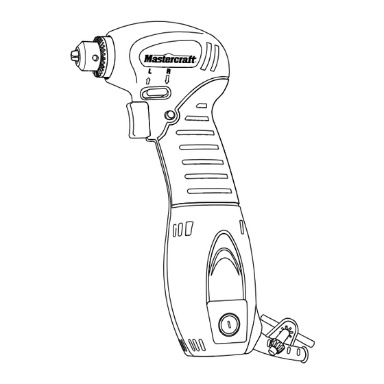
Page 8: Know Your Right Angle Drill
KNOW YOUR RIGHT ANGLE DRILL Forward/reverse switch Trigger lock-on button Chuck Handle grip Trigger switch Carbon brush cover Air vents Chuck key ACCESSORIES & CARTON CONTENTS WARNING: If any part is missing RIGHT ANGLE DRILL or damaged, do not plug the tool into COMPONENTS the power source until the missing or DESCRIPTION... -
Page 9: Carton Contents
CARTON CONTENTS ASSEMBLY AND OPERATION FORWARD/REVERSE SWITCH b) The trigger switch will NOT function with the forward/reverse switch in the middle The forward/reverse switch (1) is position. conveniently mounted above the trigger switch (2) (see Fig. 1). To make the drill rotate clockwise (for drilling) push the forward/reverse switch to the right. - Page 10 ASSEMBLY AND OPERATION VARIABLE SPEED TRIGGER SWITCH Release the trigger switch while holding the trigger switch lock button into the drill This drill is equipped with a variable speed handle and then release the lock button. ON/OFF trigger switch. The drill will continue to run. To release the trigger switch lock button, pull trigger switch To start drill, gently squeeze the trigger back and then release the trigger.
- Page 11 ASSEMBLY AND OPERATION INSTALLING BITS – cont’d REMOVING BITS Remove the drill plug from the power Insert chuck key (3) into one of three source. holes in the chuck body. Rotate chuck key clockwise until drill bit is held firmly Insert chuck key into one of three in place by the chuck jaws.
- Page 12 ASSEMBLY AND OPERATION DRILLING While holding the drill firmly, place the point of the drill bit at the point to be When drilling in smooth hard surfaces such drilled. Depress the switch trigger to as metal, use a centre punch to mark the start the drill.
- Page 13 ASSEMBLY AND OPERATION DRIVING SCREWS – cont’d Open chuck jaws and remove hex key. Select the correct screwdriver bit for Open chuck jaws as far as possible. the screw being driven. Remove the chuck screw using a Fasten the screwdriver bit into the #2 Philips screwdriver (see chuck, making sure the flats of the bit Fig.
-
Page 14: Maintenance
MAINTENANCE ASSEMBLY AND OPERATION RETIGHTENING LOOSE CHUCK GENERAL WARNING: After installing the chuck once it has been When servicing, use only identical replacement parts. Use of removed, the chuck may become loose on any other part may create a hazard or the spindle and develop a wobble. -
Page 15: Parts & Service
PARTS DIAGRAM – MODEL 54-2896-8... - Page 16 PARTS LIST – MODEL 54-2896-8 ® WARNING: When servicing, use only Mastercraft replacement parts. Use of any other parts may create a safety hazard or cause damage to the tool. Any attempt to repair or replace electrical parts on this power tool may create a safety hazard unless repair is performed by a qualified technician.
Need help?
Do you have a question about the 54-2896-8 and is the answer not in the manual?
Questions and answers