Table of Contents
Advertisement
Quick Links
Advertisement
Table of Contents

Related Manuals for Aaeon TKS-G50-QM77


Summary of Contents for Aaeon TKS-G50-QM77
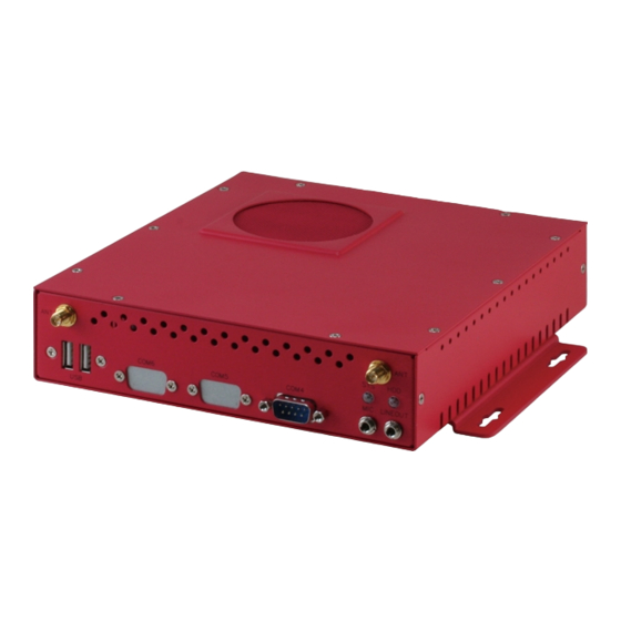
- Page 1 T K S - G 5 0 - Q M 7 7 TKS-G50-QM77 ® Intel 3rd Generation ® Core i7/ i5/ i3/ Celeron Processor 10/100/1000Base-TX Ethernet 2 USB3.0, 2 USB 2.0, 4 COM 8-bit Digital I/O 2 SATA 3.0Gb/s 1 CFast™, 1 Mini Card, LPC TKS-G50-QM77 Manual 1st Ed. October 2012...
-
Page 2: Copyright Notice
AAEON assumes no liabilities resulting from errors or omissions in this document, or from the use of the information contained herein. AAEON reserves the right to make changes in the product design without notice to its users. - Page 3 E m b e d d e d B o x T K S - G 5 0 - Q M 7 7 Acknowledgments All other products’ name or trademarks are properties of their respective owners. AMI is a trademark of American Megatrends Inc. ...
-
Page 4: Packing List
Before you begin installing your card, please make sure that the following materials have been shipped: DVD-ROM for Manual (in PDF Format) and Drivers TKS-G50-QM77 If any of these items should be missing or damaged, please contact your distributor or sales representative immediately. -
Page 5: Table Of Contents
Chapter 2 Quick Installation Guide 2.1 Safety Precautions ..........2-2 2.2 Mechanical Drawing of TKS-G50-QM77 ....2-3 2.3 A Quick Tour of the TKS-G50-QM77 ...... 2-4 2.4 Hard Disk Installation ..........2-7 2.5 Accessory Installation..........2-11 2.6 Wallmount Kit Installation........2-17 2.7 List of Jumpers ............ - Page 6 E m b e d d e d B o x T K S - G 5 0 - Q M 7 7 Chapter 4 Driver Installation 4.1 Installation……………………………………………..4-3 Appendix A Programming The Watchdog Timer A.1 Programming ............A-2 A.2 ITE8728F Watchdog Timer Initial Program ...A-6 Appendix B I/O Information B.1 I/O Address Map ............B-2 B.2 Memory Address Map..........B-4...
-
Page 7: Chapter 1 General Information
E m b e d d e d B o x T K S - G 5 0 - Q M 7 7 Chapter General Information 1- 1 Chapter 1 General Information... -
Page 8: Introduction
TKS-G50-QM77 offers high performance system that while operating in ambient temperatures ranging from 0° to 50°C. The TKS-G50-QM77 is a standalone high performance controller designed for long-life operation and with high reliability. It can replace traditional methods and become the mainstream controller for the multimedia entertainment market. -
Page 9: Features
E m b e d d e d B o x T K S - G 5 0 - Q M 7 7 1.2 Features ® ® Intel Core i7/i5/i3/Celeron Processor ® Intel QM77/HM76 204-pin DDR3 1600 MHz SODIMM x 1, Up to 8 GB ... -
Page 10: Specifications
E m b e d d e d B o x T K S - G 5 0 - Q M 7 7 1.3 Specifications ® Onboard Intel Core™ ® i7/i5/i3/Celeron processor ® Chipset Intel QM77/HM76 PCH 204-pin DDR3 1333/1600 MHz System Memory SODIMM x 1, Max. - Page 11 E m b e d d e d B o x T K S - G 5 0 - Q M 7 7 1. Fix Mode: Full Speed 2. Auto Mode: Full Speed (CPU temperature ≧55 C) and Low Speed (CPU temperature < 55 Wallmount (optional) Mounting Operating Temperature 32°F ~ 122°F (0°C ~ 50°C)
-
Page 12: Chapter 2 Quick Installation Guide
E m b e d d e d B o x T K S - G 5 0 - Q M 7 7 Chapter Quick Installation Guide Chapter 2 Quick Installation Guide... -
Page 13: Safety Precautions
E m b e d d e d B o x T K S - G 5 0 - Q M 7 7 2.1 Safety Precautions Always completely disconnect the power cord from your board whenever you are working on it. -
Page 14: Mechanical Drawing Of Tks-G50-Qm77
E m b e d d e d B o x T K S - G 5 0 - Q M 7 7 2.2 Mechanical Drawing of TKS-G50-QM77 Chapter 2 Quick Installation Guide... -
Page 15: A Quick Tour Of The Tks-G50-Qm77
T K S - G 5 0 - Q M 7 7 2.3 A Quick Tour of the TKS-G50-QM77 Before you start to set up the TKS-G50-QM77, take a moment to become familiar with the locations and purposes of the controls, drives, connections and ports, which are illustrated in the figures (Figure 2.1 to... - Page 16 E m b e d d e d B o x T K S - G 5 0 - Q M 7 7 Figure 2.2 Rear View of the TKS-G50-QM77 Power 8-bit Digital I/O with Switch VCC and ground Pin...
- Page 17 E m b e d d e d B o x T K S - G 5 0 - Q M 7 7 Figure 2.4 Bottom View of the TKS-G50-QM77 I/O cover for RAM, CFast and optional Mini Card Chapter 2 Quick Installation Guide...
-
Page 18: Hard Disk Installation
E m b e d d e d B o x T K S - G 5 0 - Q M 7 7 2.4 Hard Disk Installation Step 1: Unfasten the screws on the top of cover Chapter 2 Quick Installation Guide... - Page 19 E m b e d d e d B o x T K S - G 5 0 - Q M 7 7 Step 2: Fasten the four HDD screws and black damper, and then you can put the HDD on the opposite side for screwing Chapter 2 Quick Installation Guide...
- Page 20 E m b e d d e d B o x T K S - G 5 0 - Q M 7 7 Step 3: Putting the HDD with the HDD bracket in by 45 degree height and make sure the bracket holes are matched with the chassis stand. Step 4: Fasten the four screws of the HDD bracket and connect the HDD and power cables to the motherboard (GENE-GM77).
- Page 21 E m b e d d e d B o x T K S - G 5 0 - Q M 7 7 Step 5: Close the top cover and fasten the screws. 2-10 Chapter 2 Quick Installation Guide...
-
Page 22: Accessory Installation
E m b e d d e d B o x T K S - G 5 0 - Q M 7 7 2.5 Accessory Installation Step 1: Unfasten the 5 screws of I/O cover which is on the bottom of the chassis. - Page 23 E m b e d d e d B o x T K S - G 5 0 - Q M 7 7 Step 2: Remove the I/O cover and you can see the inside placements of RAM, CFast card, Mini Card (Mini PCIe) slot for installation. CFast ...
- Page 24 E m b e d d e d B o x T K S - G 5 0 - Q M 7 7 Step: 2-1: Insert the memory module to the Memory slot and push the module down until it has been locked by the two latches on the sides firmly. 2-13 Chapter 2 Quick Installation Guide...
- Page 25 E m b e d d e d B o x T K S - G 5 0 - Q M 7 7 Step 2-2: Insert the Mini Card module to the Mini Card slot. Push the module down until the module has been locked by two latches on the sides firmly. 2-14 Chapter 2 Quick Installation Guide...
- Page 26 E m b e d d e d B o x T K S - G 5 0 - Q M 7 7 Step 2-3: Insert the Compact-Fast card to CFast slot. Put the card bracket and fasten the screws. 2-15 Chapter 2 Quick Installation Guide...
- Page 27 E m b e d d e d B o x T K S - G 5 0 - Q M 7 7 Step 3: Put I/O cover back to the bottom of the chassis and fasten 5 screws 2-16 Chapter 2 Quick Installation Guide...
-
Page 28: Wallmount Kit Installation
E m b e d d e d B o x T K S - G 5 0 - Q M 7 7 2.6 Wallmount Kit Installation Get the brackets ready and fasten appropriate four screws on brackets. After fastening the two brackets on the bottom lid, the wallmount kit installation has been finished. -
Page 29: List Of Jumpers
E m b e d d e d B o x T K S - G 5 0 - Q M 7 7 2.7 List of Jumpers The board has a number of jumpers that allow you to configure your system to suit your application. -
Page 30: List Of Connectors
E m b e d d e d B o x T K S - G 5 0 - Q M 7 7 2.8 List of Connectors The board has a number of connectors that allow you to configure your system to suit your application. - Page 31 E m b e d d e d B o x T K S - G 5 0 - Q M 7 7 CN30 Mini Card Slot SATA1 SATA Port1 Connector SATA2 SATA Port 2 Connector 2-20 Chapter 2 Quick Installation Guide...
-
Page 32: Setting Jumpers
E m b e d d e d B o x T K S - G 5 0 - Q M 7 7 2.9 Setting Jumpers You configure your card to match the needs of your application by setting jumpers. A jumper is the simplest kind of electric switch. It consists of two metal pins and a small metal clip (often protected by a plastic cover) that slides over the pins to connect them. -
Page 33: Front Panel Connector (Jp9)
E m b e d d e d B o x T K S - G 5 0 - Q M 7 7 2.10 Front Panel Connector (JP9) Signal PWR_BTN- PWR_BTN+ HDD_LED- HDD_LED+ SPEAKER- SPEAKER+ PWR_LED- PWR_LED+ H/W RESET- H/W RESET+ 2.11 Clear CMOS (JP11) 1 2 3 1 2 3... -
Page 34: Com Port #2 Rs-232/422/485 Selection (Cn11)
E m b e d d e d B o x T K S - G 5 0 - Q M 7 7 2.12 COM Port #2 RS-232/422/485 Selection (CN11) COM2 RS-232/422/485 selection for AAEON TKS series is set in BIOS setting as following: ... - Page 35 E m b e d d e d B o x T K S - G 5 0 - Q M 7 7 TXD+ RXD- Ground RS-485 Mode Signal Signal TXD- TXD+ Ground Note: Issue: COM port limitation for the speed test during the communication. Root Cause: In serial communication, data bits received at the serial port are bundled into a byte and transmitted into the serial port hardware buffer.
-
Page 36: Digital I/O Connector (Cn12)
E m b e d d e d B o x T K S - G 5 0 - Q M 7 7 2.13 Digital I/O Connector (CN12) This connector offers 4-pair of digital I/O function. BIOS using the I2C Bus to read/write internal DIO registers and the Serial Bus address is 0xA06. - Page 37 E m b e d d e d B o x T K S - G 5 0 - Q M 7 7 Below Table for China RoHS Requirements 产品中有毒有害物质或元素名称及含量 AAEON Main Board/ Daughter Board/ Backplane 有毒有害物质或元素 部件名称 铅 汞...
-
Page 38: Chapter 3 Ami Bios Setup
E m b e d d e d B o x T K S - G 5 0 - Q M 7 7 Chapter BIOS Setup Chapter 3 AMI BIOS Setup 3-1... -
Page 39: System Test And Initialization
3. The CMOS memory has lost power and the configuration information has been erased. The TKS-G50-QM77 CMOS memory has an integral lithium battery backup for data retention. However, you will need to replace the complete unit when it finally runs down. -
Page 40: Ami Bios Setup
E m b e d d e d B o x T K S - G 5 0 - Q M 7 7 3.2 AMI BIOS Setup AMI BIOS ROM has a built-in Setup program that allows users to modify the basic system configuration. This type of information is stored in battery-backed CMOS RAM so that it retains the Setup information when the power is turned off. - Page 41 E m b e d d e d B o x T K S - G 5 0 - Q M 7 7 Setup Menu Setup submenu: Main Options summary: (default setting) System Date Day MM:DD:YYYY Change the month, year and century. The ‘Day’ is changed automatically.
- Page 42 E m b e d d e d B o x T K S - G 5 0 - Q M 7 7 Setup submenu: Advanced Options summary: (default setting) ACPI Settings System ACPI Parameters CPU Configuration CPU Configuration Parameters SATA Configuration SATA Device Options Settings AMT Configuration...
- Page 43 E m b e d d e d B o x T K S - G 5 0 - Q M 7 7 USB Configuration Parameters H/W Monitor Monitor hardware status Super IO Configuration Super IO Configuration Parameters Digital IO Port Configuration DIO configuration Chapter 3 AMI BIOS Setup 3-6...
- Page 44 E m b e d d e d B o x T K S - G 5 0 - Q M 7 7 ACPI Settings Options summary: (default setting) Enabled Enable Hibernation Disabled Enabled or disabled hibernate (OS/S4 Sleep State). Suspend Disabled S1 only(CPU Stop ACPI Sleep State...
- Page 45 E m b e d d e d B o x T K S - G 5 0 - Q M 7 7 Enabled Wake on Ring Disabled Enabled or disabled wake on ring function. RTC Wake Settings Enable system to wake from S5 using RTC alarm. Chapter 3 AMI BIOS Setup 3-8...
- Page 46 E m b e d d e d B o x T K S - G 5 0 - Q M 7 7 RTC Wake Settings Options summary: (default setting) Wake system with Disabled Fixed Time Enabled Enable or disable System wake on alarm event. Wake up time is setting by following settings.
- Page 47 E m b e d d e d B o x T K S - G 5 0 - Q M 7 7 Wake up minute 0-59 Wake up second 0-59 Wake system with Disabled Dynamic Time Enabled Enable or disable System wake on alarm event. Wake up time is current time + Increase minutes.
- Page 48 E m b e d d e d B o x T K S - G 5 0 - Q M 7 7 CPU Configuration Options summary: (default setting) Hyper-Threading Disabled Enabled En/Disable CPU Hyper-Threading function Active Processor Cores 1 to Max CPU cores Number of CPU cores to be active.
- Page 49 E m b e d d e d B o x T K S - G 5 0 - Q M 7 7 Execute Disable Bit Disabled Enabled En/Disable XD bit for supporting OS Intel Virtualization Disabled Technology Enabled En/Disable Intel VT-x function EIST Disabled Enabled...
- Page 50 E m b e d d e d B o x T K S - G 5 0 - Q M 7 7 SATA Configuration Options summary: (default setting) SATA Controller(s) Disabled Enabled En/Disable SATA controller Configure SATA as AHCI Configure SATA controller operating as IDE/AHCI/RAID mode.
- Page 51 E m b e d d e d B o x T K S - G 5 0 - Q M 7 7 Hot Plug Disabled Enabled En/Disable Hot Plug feature for specified port. Chapter 3 AMI BIOS Setup 3-14...
- Page 52 E m b e d d e d B o x T K S - G 5 0 - Q M 7 7 AMT Configuration Options summary: (default setting) Intel AMT Enabled Disabled En/Disable Intel® Active Management Technology BIOS Extension. Note: iAMT H/W is always enabled.
- Page 53 E m b e d d e d B o x T K S - G 5 0 - Q M 7 7 USB Configuration Options summary: (default setting) Legacy USB Support Enabled Disabled Auto Enables BIOS Support for Legacy USB Support. When enabled, USB can be functional in legacy environment like DOS.
- Page 54 E m b e d d e d B o x T K S - G 5 0 - Q M 7 7 Enables BIOS Support for USB3.0 (XHCI). When disabled, PCH USB3.0 controller will also be disabled. Device Name Auto (Emulation Type) Floppy...
- Page 55 E m b e d d e d B o x T K S - G 5 0 - Q M 7 7 H/W Monitor Fixed Mode Easy Fan Mode Auto Mode Fix Mode: Full Speed. ≧ ℃ <55 ) ℃...
- Page 56 E m b e d d e d B o x T K S - G 5 0 - Q M 7 7 COM Port Configuration Options summary: (default setting) Serial Port 1/2/3/4 Configuration Set Parameters of Serial Port 1/2 Power Off Restore AC Power Loss Power On...
- Page 57 E m b e d d e d B o x T K S - G 5 0 - Q M 7 7 Enabled Configure Energy-using Product(EuP) Power Control. Chapter 3 AMI BIOS Setup 3-20...
- Page 58 E m b e d d e d B o x T K S - G 5 0 - Q M 7 7 Serial Port 1 Configuration Options summary: (default setting) Serial Port Disabled Enabled En/Disable specified serial port. Change Settings Auto IO=3F8h;...
- Page 59 E m b e d d e d B o x T K S - G 5 0 - Q M 7 7 IO=3E8h; IRQ=3,4,5,7,10,11,12; IO=2E8h; IRQ=3,4,5,7,10,11,12; Select a resource setting for Super IO device. Chapter 3 AMI BIOS Setup 3-22...
- Page 60 E m b e d d e d B o x T K S - G 5 0 - Q M 7 7 Serial Port 2 Configuration Options summary: (default setting) Serial Port Disabled Enabled En/Disable specified serial port. Change Settings Auto IO=2F8h;...
- Page 61 E m b e d d e d B o x T K S - G 5 0 - Q M 7 7 IO=3E8h; IRQ=3,4,5,7,10,11,12; IO=2E8h; IRQ=3,4,5,7,10,11,12; Select a resource setting for Super IO device. Device Type RS232 RS422 RS485 Configure COM2 operated as RS232, RS422 or RS485.
- Page 62 E m b e d d e d B o x T K S - G 5 0 - Q M 7 7 Serial Port 3 Configuration Options summary: (default setting) Serial Port Disabled Enabled En/Disable specified serial port. Change Settings Auto IO=3E8h;...
- Page 63 E m b e d d e d B o x T K S - G 5 0 - Q M 7 7 IO=3E8h; IRQ=3,4,5,7,10,11,12; IO=2E8h; IRQ=3,4,5,7,10,11,12; Select a resource setting for Super IO device. Chapter 3 AMI BIOS Setup 3-26...
- Page 64 E m b e d d e d B o x T K S - G 5 0 - Q M 7 7 Serial Port 4 Configuration Options summary: (default setting) Serial Port Disabled Enabled En/Disable specified serial port. Change Settings Auto IO=2E8h;...
- Page 65 E m b e d d e d B o x T K S - G 5 0 - Q M 7 7 IO=3E8h; IRQ=3,4,5,7,10,11,12; IO=2E8h; IRQ=3,4,5,7,10,11,12; Select a resource setting for Super IO device. Chapter 3 AMI BIOS Setup 3-28...
- Page 66 E m b e d d e d B o x T K S - G 5 0 - Q M 7 7 Digital IO Port Configuration Options summary: (default setting) GPIO1/GPIO2/GPIO3/ Input GPIO4 Direction Output Set GPIO1/GPIO2/GPIO3/GPIO4 as Input or Output GPIO5/GPIO6/GPIO7/ Input GPIO8 Direction...
- Page 67 E m b e d d e d B o x T K S - G 5 0 - Q M 7 7 Setup submenu: Chipset Options summary: (default setting) Onboard Device Configure Onboard Devices PCI-IO Configuration South Bridge Parameters Memory Configuration Memory Parameters...
- Page 68 E m b e d d e d B o x T K S - G 5 0 - Q M 7 7 Onboard Device Options summary: (default setting) Onboard HD Audio Disabled Enabled Auto En/Disabled HD Audio controller. HD Audio Internal Disabled HDMI Codec Enabled...
- Page 69 E m b e d d e d B o x T K S - G 5 0 - Q M 7 7 En/Disabled Intel i82579 NIC Realtek LAN Enabled Controller Disabled En/Disabled Realtek RTL8111E NIC Chapter 3 AMI BIOS Setup 3-32...
- Page 70 E m b e d d e d B o x T K S - G 5 0 - Q M 7 7 PCH-IO Configuration Options summary: (default setting) Power Mode 128MB 256MB Select the power type used on the system PCIe MiniCard Slot Disabled Enabled...
- Page 71 E m b e d d e d B o x T K S - G 5 0 - Q M 7 7 Select PCI Express port speed. Some PCIe card must set to Gen1 for operation. Chapter 3 AMI BIOS Setup 3-34...
- Page 72 E m b e d d e d B o x T K S - G 5 0 - Q M 7 7 Host Bridge Options summary: (default setting) DIMM Profile Default DIMM profile XMP Profile 1 XMP Profile 2 Select DIMM timing profile that should be used Memory Frequency Auto...
- Page 73 E m b e d d e d B o x T K S - G 5 0 - Q M 7 7 Max TOLUD Dynamic 1 GB 1.25 GB 1.5 GB 1.75 GB 2 GB 2.25 GB 2.5 GB 2.75 GB 3 GB 3.25 GB...
- Page 74 E m b e d d e d B o x T K S - G 5 0 - Q M 7 7 Graphic Configuration Options summary: (default setting) GTT Size Select the GTT Size Aperture Size 128MB 256MB 512MB Select the Aperture Size DVMT 64MB...
- Page 75 E m b e d d e d B o x T K S - G 5 0 - Q M 7 7 Select DVMT 5.0 Pre-Allocated (Fixed) Graphics Memory size used by the Internal Graphics Device. DVMT Total Gfx 128MB 256MB Select DVMT 5.0 Total Graphic Memory size used by the Internal...
- Page 76 E m b e d d e d B o x T K S - G 5 0 - Q M 7 7 Setup submenu: Boot Options summary: (default setting) Quiet Boot Disabled Enabled En/Disable showing boot logo. Launch LAN PXE Disabled OpROM Enabled...
- Page 77 E m b e d d e d B o x T K S - G 5 0 - Q M 7 7 BBS Priorities Options summary: (default setting) Boot Option #x Disabled Device name Sets the system boot order Chapter 3 AMI BIOS Setup 3-40...
- Page 78 E m b e d d e d B o x T K S - G 5 0 - Q M 7 7 Setup submenu: Security Options summary: (default setting) Administrator Not set Password/ User Password Chapter 3 AMI BIOS Setup 3-41...
- Page 79 E m b e d d e d B o x T K S - G 5 0 - Q M 7 7 You can install a Supervisor password, and if you install a supervisor password, you can then install a user password. A user password does not provide access to many of the features in the Setup utility.
- Page 80 E m b e d d e d B o x T K S - G 5 0 - Q M 7 7 Setup submenu: Exit Options summary: (default setting) Save Changes and Reset Reset the system after saving the changes Discard Changes and Reset Reset system setup without saving any changes...
- Page 81 E m b e d d e d B o x T K S - G 5 0 - Q M 7 7 Restore the User Defaults to all the setup options Chapter 3 AMI BIOS Setup 3-44...
-
Page 82: Chapter 4 Driver Installation
E m b e d d e d B o x T K S - G 5 0 - Q M 7 7 Chapter Driver Installation 4 -1 Chapter 4 Driver Installation... - Page 83 E m b e d d e d B o x T K S - G 5 0 - Q M 7 7 The TKS-G50-QM77 comes with an AutoRun DVD-ROM that contains all drivers and utilities that can help you to install the driver automatically.
- Page 84 T K S - G 5 0 - Q M 7 7 4.1 Installation: Insert the TKS-G50-QM77 DVD-ROM into the DVD-ROM drive. And install the drivers from Step 1 to Step 10 in order. Step 1 – Install Chipset Driver...
- Page 85 E m b e d d e d B o x T K S - G 5 0 - Q M 7 7 dotNet Framework first. Simply click on dotnetfx35.exe located in dotNet Framwork folder. Step 3 –Install LAN1 Driver (Realtek Chip) Click on the STEP3-LAN1(Realtek) folder and select the OS folder your system is Double click on the setup.exe file located in each OS...
- Page 86 E m b e d d e d B o x T K S - G 5 0 - Q M 7 7 folder your system is Double click on the Setup.exe file located in each OS folder Follow the instructions that the window shows The system will help you install the driver automatically Step 7 –...
- Page 87 E m b e d d e d B o x T K S - G 5 0 - Q M 7 7 select the OS folder your system is Double click on the .exe file located in each OS folder Follow the instructions that the window shows The system will help you install the driver automatically 4 -6...
-
Page 88: Appendix A Programming The Watchdog Timer
E m b e d d e d B o x T K S - G 5 0 - Q M 7 7 Appendix Programming the Watchdog Timer Appendix A Programming the Watchdog Timer... -
Page 89: Programming
E m b e d d e d B o x T K S - G 5 0 - Q M 7 7 A.1 Programming TKS-G50-QM77 utilizes ITE IT8728F chipset as its watchdog timer controller. Below are the procedures to complete its configuration and the AAEON intial watchdog timer program is also attached based on which you can develop customized program to fit your application. - Page 90 E m b e d d e d B o x T K S - G 5 0 - Q M 7 7 There are three steps to complete the configuration setup: (1) Enter the MB PnP Mode; (2) Modify the data of configuration registers; (3) Exit the MB PnP Mode.
- Page 91 E m b e d d e d B o x T K S - G 5 0 - Q M 7 7 WatchDog Timer Configuration Registers Configure Control (Index=02h) This register is write only. Its values are not sticky; that is to say, a hardware reset will automatically clear the bits, and does not require the software to clear them.
- Page 92 E m b e d d e d B o x T K S - G 5 0 - Q M 7 7 WatchDog Timer Control Register (Index=71h, Default=00h) WatchDog Timer Configuration Register (Index=72h, Default=00h) WatchDog Timer Time-out Value Register (Index=73h, Default=00h) Appendix A Programming the Watchdog Timer...
-
Page 93: Ite8728F Watchdog Timer Initial Program
E m b e d d e d B o x T K S - G 5 0 - Q M 7 7 A.2 ITE8728F Watchdog Timer Initial Program .MODEL SMALL .CODE Main: CALL Enter_Configuration_mode CALL Check_Chip mov cl, 7 call Set_Logic_Device ;time setting mov cl, 10 ;... - Page 94 E m b e d d e d B o x T K S - G 5 0 - Q M 7 7 ; game port enable mov cl, 9 call Set_Logic_Device Initial_OK: CALL Exit_Configuration_mode MOV AH,4Ch INT 21h Enter_Configuration_Mode PROC NEAR MOV SI,WORD PTR CS:[Offset Cfg_Port] MOV DX,02Eh MOV CX,04h...
- Page 95 E m b e d d e d B o x T K S - G 5 0 - Q M 7 7 Exit_Configuration_Mode ENDP Check_Chip PROC NEAR MOV AL,20h CALL Read_Configuration_Data CMP AL,87h JNE Not_Initial MOV AL,21h CALL Read_Configuration_Data CMP AL,12h JNE Not_Initial Need_Initial:...
- Page 96 E m b e d d e d B o x T K S - G 5 0 - Q M 7 7 MOV DX,WORD PTR CS:[Cfg_Port+06h] IN AL,DX Read_Configuration_Data ENDP Write_Configuration_Data PROC NEAR MOV DX,WORD PTR CS:[Cfg_Port+04h] OUT DX,AL XCHG AL,AH MOV DX,WORD PTR CS:[Cfg_Port+06h] OUT DX,AL...
- Page 97 E m b e d d e d B o x T K S - G 5 0 - Q M 7 7 push ax push cx xchg al,cl mov cl,07h call Superio_Set_Reg pop cx pop ax Set_Logic_Device endp ;Select 02Eh->Index Port, 02Fh->Data Port Cfg_Port DB 087h,001h,055h,055h DW 02Eh,02Fh END Main...
-
Page 98: Appendix B I/O Information
E m b e d d e d B o x T K S - G 5 0 - Q M 7 7 Appendix I/O Information Appendix B I/O Information... -
Page 99: I/O Address Map
S u b C o m p a c t B o a r d T K S - G 5 0 - Q M 7 7 B.1 I/O Address Map Appendix B I/O Information... - Page 100 E m b e d d e d B o x T K S - G 5 0 - Q M 7 7 Appendix B I/O Information...
-
Page 101: Memory Address Map
S u b C o m p a c t B o a r d T K S - G 5 0 - Q M 7 7 B.2 Memory Address Map Appendix B I/O Information... -
Page 102: Irq Mapping Chart
E m b e d d e d B o x T K S - G 5 0 - Q M 7 7 B.3 IRQ Mapping Chart B.4 DMA Channel Assignments Appendix B I/O Information... -
Page 103: Appendix C Mating Connector
E m b e d d e d B o x T K S - G 5 0 - Q M 7 7 Appendix Mating Connector C - 1 Appendix C Mating Connector... -
Page 104: List Of Mating Connectors And Cables
E m b e d d e d B o x T K S - G 5 0 - Q M 7 7 C.1 List of Mating Connectors and Cables The table notes mating connectors and available cables. Connector Function Mating Connector Available Cable P/N... - Page 105 E m b e d d e d B o x T K S - G 5 0 - Q M 7 7 AAEON CN14 LPC Port SHR-12V-S-B 1703120130 Cable Serial COM Port 4 Port CN15 Molex 51021-0900 1701090150 Connector...
-
Page 106: Appendix D Ahci Setting
E m b e d d e d B o x T K S - G 5 0 - Q M 7 7 A ppendix AHCI Setting Appendix D AHCI Setting... -
Page 107: Setting Ahci
E m b e d d e d B o x T K S - G 5 0 - Q M 7 7 D.1 Setting AHCI OS installation to SETUP AHCI Mode Step 1: Copy below files from “Driver CD -> STEP7 - AHCI\WinXP_32”... - Page 108 E m b e d d e d B o x T K S - G 5 0 - Q M 7 7 Step 4: Configure DVD/CD-ROM drive as the first boot device. Step 5: Save changes and exit BIOS SETUP Appendix D AHCI Setting...
- Page 109 E m b e d d e d B o x T K S - G 5 0 - Q M 7 7 Step 6 – Boot to DVD/CD-ROM device to install OS Step 7 – Press “F6” to install AHCI driver Step 8 –...
-
Page 110: Appendix E Digital I/O Ports
E m b e d d e d B o x T K S - G 5 0 - Q M 7 7 Appendix Digital I/O Ports E - 1 AppendixE Digital I/O Ports... -
Page 111: Electrical Specifications For I/O Ports
E m b e d d e d B o x T K S - G 5 0 - Q M 7 7 E.1 Electrical Specifications for Digital I/O Ports Table 1 : Digital Input/Output Pin Electrical Specification Input Threshold Output Voltage Type Voltage Note Low High Low High DIO1 ... -
Page 112: Dio Programming
T K S - G 5 0 - Q M 7 7 E.2 DIO Programming TKS-G50-QM77 utilizes ITE IT8728F chipset as its Digital I/O controller. Below are the procedures to complete its configuration and the AAEON initial DIO program is also attached based on which you can develop customized program to fit your application. -
Page 113: Digital I/O Register
E m b e d d e d B o x T K S - G 5 0 - Q M 7 7 E.3 Digital I/O Register Table 2 : SuperIO relative register table Default Value Note SIO MB PnP Mode Index Register Index 0x2E 0x2E or 0x4E SIO MB PnP Mode Data Register Data 0x2F 0x2F or 0x4F Table 3 : Digital Input/Output relative register table Register ... -
Page 114: Digital I/O Sample Program
E m b e d d e d B o x T K S - G 5 0 - Q M 7 7 E.4 Digital I/O Sample Program ************************************************************************** // SuperIO relative definition (Please reference to Table 2) #define SIOIndex 0x2E #define SIOData 0x2F #define DIOLDN... - Page 115 E m b e d d e d B o x T K S - G 5 0 - Q M 7 7 InputStatus : 0: Digital I/O Pin level is low 1: Digital I/O Pin level is High PinStatus = AaeonReadPinStatus( Pin3Bit // Procedure : AaeonSetOutputLevel // Input :...
- Page 116 E m b e d d e d B o x T K S - G 5 0 - Q M 7 7 IOWriteByte(SIOIndex, 0x01); IOWriteByte(SIOIndex, 0x55); IOWriteByte(SIOIndex, 0x55); SIOExitMBPnPMode() VOID IOWriteByte(SIOIndex, 0x02); IOWriteByte(SIOData, 0x01); SIOSelectLDN(byte LDN) VOID IOWriteByte(SIOIndex, 0x07); // SIO LDN Register Offset = 0x07 IOWriteByte(SIOData, ********************************************************************************...
- Page 117 E m b e d d e d B o x T K S - G 5 0 - Q M 7 7 Byte TmpValue; SIOEnterMBPnPMode(); SIOSelectLDN(DIOLDN); If (PinBit < Pin4Bit) { IOWriteByte(SIOIndex, DirReg1); TmpValue = IOReadByte(SIOData); TmpValue &= (1 << PinBit); TmpValue |= (Mode <<...
Need help?
Do you have a question about the TKS-G50-QM77 and is the answer not in the manual?
Questions and answers