Table of Contents

Subscribe to Our Youtube Channel
Related Manuals for MIMAKI JV4 Series


Summary of Contents for MIMAKI JV4 Series
- Page 1 MIMAKI ENGINEERING CO., LTD. TKB Gotenyama Building, 5-9-41, Kitashinagawa, Shinagawa-ku, Tokyo 141-0001, Japan Phone: +81-3-5420-8671 Fax: +81-3-5420-8687 URL: http: // www.mimaki. co. jp / E-mail: trading@mimaki.co.jp D200571...
- Page 3 ING CO., LTD. has been informed of the possible risk of such damages in prior. For example, MIMAKI shall not be liable to any damage to medium (works) due to the use of the product or any indirect damage that is caused by a product that is manufactured with damaged medium.
- Page 4 Operation of this equipment in a residential area is likely to cause harmful interference in which cause the user will be required to correct the interference at his own expense. • In the case where MIMAKI-recommended cable is not used for con- nection of this device, limits provided by FCC rules can be exceeded.
-
Page 5: Foreword
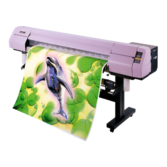
FOREWORD Congratulations on your purchase of a MIMAKI "JV4 Series" model of color ink jet printer. Model JV4 Series is a color ink jet plotter which is capable of producing images in up to six different colors at high speeds. -
Page 6: Features
APPLICABILITY OF NEW TYPES OF INK (WATER-SOLUBLE DYE INK AND DISPERSE DYE INK) MIMAKI offers the following three types of ink that can be used with the device. • Water-soluble pigment ink The conventional pigment-based ink. Having excellent light fastness, this type of ink is most suitable for outdoor print on large-sized color sign displays (e.g., signboards). - Page 7 INDICATION OF THE AMOUNT OF REMAINING INK Since the amount of ink that remains can be checked even during operation of the device, you can use the ink and medium without waste. EASY-TO-SEE DISPLAY The LCD panel displays the device setting menu in two lines (not one line), making it easier to see. Since the LCD panel is provided with a backlight, the display can be clearly seen even in a dark place.
-
Page 8: For Safe Operation
FOR SAFE OPERATION PICTORIAL SIGNS Pictorial signs are used in this Instruction Manual for safe operation of and in prevention of damages to the device. Pictorial signs and their meanings are given below. Read and fully understand before reading the text. •... -
Page 9: Never Do The Following
Never refill the ink cartridge with • Never repair your device by yourself ink. since it is very dangerous for you to MIMAKI assumes no do so. responsibility for malfunction Roll paper caused by using the device after •... -
Page 10: Precautions In Use
There are some parts which before starting printing. If the must be replaced by service device performs printing without men after JV4 series are in use the casters locked, the device can for 5000 hours from 3000 hours. move out of position. -
Page 11: Precautions In Installation
CAUTION Ink cartridges If the ink cartridge is moved from • • Be sure to store ink cartridges a cold place to a warm place, in a cold and dark place. leave it in the room temperature • Never replenishes the ink for three hours or more before cartridge with ink. -
Page 12: Table Of Contents
TABLE OF CONTENTS FOREWORD ........................I FEATURES ........................II FOR SAFE OPERATION ....................IV PICTORIAL SIGNS ..............................IV EXAMPLE OF PICTORIAL SIGNS ......................... IV NEVER DO THE FOLLOWING ..........................V PRECAUTIONS IN USE ............................VI PRECAUTIONS IN INSTALLATION ........................VII HOW TO READ THIS OPERATION MANUAL ............ - Page 13 INK CARTRIDGES ..................... 1.23 INK STATIONS ..............................1.23 TYPES OF INK ..............................1.24 PRECAUTIONS IN HANDLING THE INK CARTRIDGE ..................1.25 DISPLAY OF INK TYPE ............................1.25 INITIAL SETTING OF INKS ..................1.26 SETTING INK CARTRIDGES ..................1.27 SETTING FOR 1-WAY HIGH-SPEED PRINTING ....................1.27 SETTING FOR 2-WAY MULTI PRINTING ......................
- Page 14 ROUTINE MAINTENANCE ..................2.11 WHEN THE DEVICE IS LEFT UNUSED FOR A LONG PERIOD OF TIME ............2.11 NOTES ON CLEANING ............................2.11 REMOVING PAPER CHIPS ..........................2.11 CLEANING WIPERS ............................2.11 CLEANING INK AT SLIDER BOTTOM ........................ 2.12 MAINTENANCE FOR FRAME COMPONENTS ....................2.12 CHAPTER 3 HOW TO USE THE APPLICATION FUNCTIONS APPLICATION FUNCTIONS ..................
- Page 15 MAINTENANCE FUNCTIONS ..................4.4 DRAWING SETUP CONDITIONS [LIST] ......................4.4 PLOTTING HEX CODE OF PLOTTING COMMAND [DATA DUMP] ..............4.5 CORRECTING THE DOT POSITIONS AFTER ADJUSTING THE HEAD HEIGHT [PRINTADJUST] ....4.6 MOVING THE CARRIAGE TO CLEAN THE STATION INTERIOR [CARRIAGEOUT] ......... 4.8 IF A DEFECTIVE PLOTTING IS NOT CORRECTED EVEN AFTER THE CLEANING FUNCTION IS EXECUTED ..............................
-
Page 16: How To Read This Operation Manual
HOW TO READ THIS OPERATION MANUAL HOW TO READ THIS OPERATION MANUAL The titlle in each chapter are provided. The item to select from the setting This manual describes menu before each the procedure of device operation is operation of th device. explained. -
Page 17: Display On The Lcd And Indication Of The Keys
DISPLAY ON THE LCD AND INDICATION OF THE KEYS In this instruction manual, the characters displayed on the LCD of the operation panel (see page 2.2) and the keys used to operate the device are explained, together with the operation procedure. Operate the device while confirming the display on the LCD. -
Page 18: Structure Of This Instruction Manual
STRUCTURE OF THIS INSTRUCTION MANUAL CHAPTER 1 SET-UP This chapter describes the procedures for unpacking and assembling the device, and for setting up the device such as setting inks and medium. CHAPTER 2 HOW TO USE THE BASIC FUNCTIONS This chapter describes the basic operations of the device, from the begin- ning to the end of plotting. - Page 19 CHAPTER 1 SET-UP This chapter describes the procedures for unpacking and assembling the device, and for setting up device such as setting inks and medium. TABLE OF CONTENTS WHERE TO INSTALL THE DEVICE ................ 1.2 CHECKING THE ACCESSORIES ................1.3 CONFIGURATION AND FUNCTION ..............
-
Page 20: Where To Install The Device
WHERE TO INSTALL THE DEVICE Secure a suitable installation space before assembling the device. The place of installation must have space required not only for the device itself but also for plotting operation. Model Width Depth Height Gross weight JV4-130 2410 mm 730 mm 1205 mm... -
Page 21: Checking The Accessories
CHECKING THE ACCESSORIES Open the packing box and check the components in it. If you find any missing accessory or damaged one, contact your local dealer or MIMAKI office. Main unit Take-up device Left stand Right stand Stay Waste ink tank (2 pcs.) 1000 cc (1 pcs.) - Page 22 Instruction manual (this manual) Power cable Hexagonal wrench (L) Phillips screwdriver M4 cap bolt for fitting the M8 cap bolt (long) take-up device (4 pcs, 8 pcs JV4-180) for fitting the stay (2 pcs) M8 cap bolt (Short) IEEE1394 Driver for fitting the main unit (2 pcs) (for Windows2000) Blush...
-
Page 23: Configuration And Function
CONFIGURATION AND FUNCTION FRONT FACE Name Function Front cover It is opened when setting medium or taking a corrective measure against a medium jam. Power switch It turns on/off the power to the device. IEEE-1394 connector A 400M bps interface connector compatible with IEEE-1394. Parallel connector Bi-directional parallel interface connector (complies with IEEE1284) AC inlet... -
Page 24: Rear Face
REAR FACE Name Function F ink station This station houses up to six ink cartridges. Clamp lever It is made to go up-down the pinch roller for holding medium. Roll holder Roll holder is inserted in the right and left core of roll medium to hold the roll medium. -
Page 25: Names And Functions Of The Parts Under The Front Cover
NAMES AND FUNCTIONS OF THE PARTS UNDER THE FRONT COVER Under the front cover, there are the carriage, capping station, etc. necessary for plotting operation. The mechanisms provided under the front cover are explained below. CARRIAGE The carriage is provided with ink heads for plotting, a cutter unit for cutting off medium, etc. It is also provided with a head height adjustment screw for adjusting the head height according to the thickness of the medium used. -
Page 26: Capping Station
CAPPING STATION The capping station consists of ink caps, wipers for cleaning the heads, etc. : It covers the nozzle so as to prevent the head nozzle from drying up. Wiper : It is used to clean the head nozzle. Wiper Ink cap THE PINCH ROLLER AND THE FEED ROLLER... -
Page 27: The Medium Sensor
• When a sheet of paper is used as the medium, set it in position taking care that it does not come outside the guide holes in the right-hand part of the platen. Medium sensor Medium guide Platen THE MEDIUM SENSOR The medium sensors detects the presence of the medium and the medium length. -
Page 28: Cutter Blade And Cutting Line
CUTTER BLADE AND CUTTING LINE The carriage is provided with a cutter unit for cutting off the medium that has been plotted on. The cutting line along which to cut off the medium is shown below. For the method of cutting a medium, see “Cutting by Hand” (page 2.7) or “Automatic Cutting [AUTO Cut]”... -
Page 29: Head Height Adjustment Rod And Adjustment Screw
HEAD HEIGHT ADJUSTMENT ROD AND ADJUSTMENT SCREW When a medium is set on the device for the first time or when a medium different in thickness from the current medium is set on the device, it is necessary to adjust the height of the heads. •... -
Page 30: Unpacking And Assembling
UNPACKING AND ASSEMBLING ASSEMBLING THE PEDESTALS AND THE DEVICE • The pack of the device is as heavy as approximately 200 kg. Perform the assembly work by at least four persons to ensure safety. • Exercise added care not to drop the main unit on your feet. 1. - Page 31 3. Take the stands out of the package. Direct the stands so that round tapped holes for the screws are faced outside. Set up each stand with the side having a groove for fitting the stay coming inside. Long Short Front face 4.
-
Page 32: Install The Take-Up Device
6. Holding both ends of the main unit with four persons. Hold up the device at the pedestal support bars. 7. Place the main unit on the stands while exer- cising care not to allow hands to be caught between them. Set the device on the stand at the position where the screw holes in the device align with the screw holes in the tops of the stands. -
Page 33: Putting On The Maintenance Cover
2. Insert the cable of take-up device into the connector located at the bottom of the capping station. PUTTING ON THE MAINTENANCE COVER 1. Put on the maintenance cover. Operation panel 2. Fix the maintenance cover with the screws. Screw •... -
Page 34: Installing The Roll Holders
Right side of Waste ink tank. 1. Insert the large waste ink tank to the right side bracket and raise up. 2. Rotate the waste ink tank assy 90 degrees to back. 3. Close the bracket and fix with the stop screw. 2000 cc INSTALLING THE ROLL HOLDERS 1. -
Page 35: Moving The Device
MOVING THE DEVICE The method of moving the assembled device to the place of installation, etc. is explained below. When moving the device, unlock the caster stoppers. • When moving the device, take care not to apply excessive shock to it. •... -
Page 36: Connecting The Cables
Configuration of connector (IEEE1284) • If the customer uses Windows 2000 and the computer is not provided with an IEEE 1394 board, contact your nearest RIP provider or MIMAKI sales office. - 1.18 -... -
Page 37: Connecting The Power Cable
CONNECTING THE POWER CABLE Connect the power cable as described below. Connect the power cable to the receptacle of the following specifications. • Voltage AC 100 – 240 V ±10% • Frequency 50/60 Hz ±1% • Capacity 4 A or more (400 W or more) •... -
Page 38: Switching On/Off The Power Supply
SWITCHING ON/OFF THE POWER SUPPLY After setting up the device, switch on and off the power as described below. TURNING THE POWER ON 1. Turn on the power to the device. Tilt the power switch toward the “ I ”side, and the power to the device is turned on. -
Page 39: Turning The Power Off
TURNING THE POWER OFF To turn the power off, check first whether or not there is data received and there remains data that has not yet been output in the device. Also be sure that the head rests at the capping station. •... -
Page 40: Front Cover
FRONT COVER OPENING/CLOSING THE FRONT COVER Do not open the front cover while the device is in operation. If you open the front cover during plotting, the carriage will stop for safety, reselting in abortion of plotting. In this case, re-start the device and computer following the procedure described below. •... -
Page 41: Ink Cartridges
INK CARTRIDGES INK STATIONS As viewed from the front of the device, the ink station on the right side is called the “R-row ink station” and the ink station on the left side is called the “F-row ink station.” F-row ink station Capable of housing six ink cartridges, this ink station supplies ink to... -
Page 42: Types Of Ink
In each of the two ink stations of the device, four types of ink can be used. The characteristics of each ink type are described below. • Be sure to use the inks and ink cartridges specified by MIMAKI. • Water-soluble pigment ink [Pigcm] : A pigment-based ink having good weather resistance. -
Page 43: Precautions In Handling The Ink Cartridge
• Never refill the ink cartridge with ink. Refilling the ink cartridge can cause a trouble. Remember that Mimaki assumes no responsibility for any damage caused by the use of the ink cartridge replenished with ink. -
Page 44: Initial Setting Of Inks
INITIAL SETTING OF INKS When using the device for the first time, it is necessary to install ink cartridges in the device. Use the following procedure to install the ink cartridges. STEP 1. Turn the power on. INK TYPE After the initial operation, the device displays the type of ink R : Pigcm F : Dye set in each ink station. -
Page 45: Setting Ink Cartridges
SETTING INK CARTRIDGES SETTING FOR 1-WAY HIGH-SPEED PRINTING New piezo electric heads, the staggered-layout print head provides more attractive, faster printing, and allows ultra high-precisions 6-head 1-way printing. SAME SETS R-row ink station A six-color set F-row ink station A six-color set High-speed plotting using water-soluble pigment ink (Light set) High-speed plotting using water-soluble pigment ink (Orange, Green set) High-speed plotting using Water-soluble dye ink... -
Page 46: Setting For 2-Way Multi Printing
SETTING FOR 2-WAY MULTI PRINTING Alternatively, using two sets of three heads in 2-way printing mode, each with different inks, gives you the functionality of two 6-color plotters in a single unit. The following six combinations are possible. • Before starting the plotting operation, select the ink type to be used (See page 1.26). - Page 47 DIFFERENT SETS ≠ R-row ink station A six-color set F-row ink station A six-color set Setting water-soluble pigment ink (Orange, Green set) and Disperse dye ink Setting water-soluble dye ink and Disperse dye ink • During initial ink setting or ink change, register the appropriate ink type for each ink station (See page 1.26).
-
Page 48: To Replenish Ink, Set A New Ink Cartridge In The Ink Station
TO REPLENISH INK, SET A NEW INK CARTRIDGE IN THE INK STATION. Ink replenishment is done by replacing the ink cartridge with a new one. If the ink cartridge is not replaced, plotting is interrupted if the ink runs out. If the message [INKnearEND] appears, immediately load a new ink cartridge. -
Page 49: Medium That Can Be Used
: Artwork film, Canvas, Tarpaulin, Waterproof olefin film, (Board) Sizes of medium that can be used The size of medium varies according to model of the JV4 series. Refer to the following table for the model used. Medium Size JV4-130... -
Page 50: Precautions In Handling The Medium
• Use the medium specified by MIMAKI. Use the medium exclusive for the device. Please be noted that MIMAKI ENGINEERING CO., LTD. shall have no liability for any trouble that arises when using any medium other than the medium exclusively developed for the device. -
Page 51: Notes On Handling A Board For The Medium
NOTES ON HANDLING A BOARD FOR THE MEDIUM • When a board is used as the medium, be sure to adjust the head height beforehand. Otherwise, the head can be damaged by making contact with the board during plotting. • When the medium is changed from a board to a thinner medium, be sure to adjust the head height too. -
Page 52: Before Setting The Medium On The Device
BEFORE SETTING THE MEDIUM ON THE DEVICE ADJUSTING THE HEAD HEIGHT WHEN THE MEDIUM USED IS CHANGED [HEAD HEIGHT] When the medium used is changed, it is necessary to adjust the head height according to the thickness of the new medium. If the height of the head is inappropriate to the thickness of the medium, the plotter cannot work properly. - Page 53 2. Push down the head height adjustment rod by the right hand. Push down the head height adjustment rod till it stops moving anymore. • If the tip of the head height adjustment rod makes contact with the surface of the medium, repeat step (6)-1 shown on the preceding page to raise the head.
-
Page 54: Points In Head Height Adjustment
POINTS IN HEAD HEIGHT ADJUSTMENT • When the head height is so adjusted that the tip of the head height adjustment rod just makes contact with the surface of the medium, the distance between the head and the printing surface of the medium becomes optimum. •... -
Page 55: Setting The Medium On The Device
SETTING THE MEDIUM ON THE DEVICE The medium that can be used with the device are roll medium, cut sheet medium, and board (See page 1.31). SETTING A PAPER ROLL ON THE DEVICE The procedure for setting roll medium on the device is described below. Use roll medium exclusive for the device. - Page 56 3. Loosen the screw of the right-hand roll holder. Adjust the roll holder position to the width of the roll medium. By placing the roll medium on the medium support bar, the position of roll holder can be adjusted easily. 4.
- Page 57 6. Insert the roll medium that has been pull out between the platen and the pinch rollers and pull it to the front of the device. 7. Push the clamp lever at the back of the device. Fix the roll medium with the pinch rollers to prevent it from slipping out.
- Page 58 9. Open the front cover and pull out the roll medium. Take care not to crease the roll medium while it is pulled out. 10. Push down the clamp lever at the front of the device. Fix the roll medium that has been pulled out with the pinch rollers.
- Page 59 After setting the medium After the medium is set and the front cover is closed, the carriage starts moving to detect the me- dium. When the medium is detected, the device enters the LOCAL mode. << LOCAL >> width : 1272mm Display on the LCD When couting the amount of remaining roll media, input the length of set media.
-
Page 60: Setting Cut Sheet Medium On The Device
SETTING CUT SHEET MEDIUM ON THE DEVICE Unlike roll medium, the cut sheet medium need not be fixed onto the roll holders. The sheet paper may be set on the device either from the front or back of the device. •... - Page 61 4. Close the front cover. The device starts detecting the medium. 5. Push the [ENTER] key. << LOCAL >> After the initial operation, the device enter the LOCAL mode. width : 1272mm (See page 1-20) 6. Push down the clamp lever at the front of the device.
-
Page 62: Setting A Board Medium On The Device
SETTING A BOARD MEDIUM ON THE DEVICE Unlike a paper roll, the board medium need not be fixed onto the roll holders. The board medium may be set on the device either from the front or back of the device. •... - Page 63 Align the edge of the front side of the board with • the guide (absorption hole) which is the closest to you provided on the platen. Board Guide for Board medium 4. Close the front cover. The device starts detecting the medium. 5.
-
Page 64: Specifying The Scope Of Plotting On The Medium Used (Effective Plotting Area)
SPECIFYING THE SCOPE OF PLOTTING ON THE MEDIUM USED (EFFECTIVE PLOTTING AREA) The device has an area which cannot perform printing, due to mechanical reasons. This area is called “dead space.” The effective printing area is obtained by excluding the dead space from the printing medium. Note that the minimum value of dead space differs from one model to another. -
Page 65: Establishing An Origin
ESTABLISHING AN ORIGIN Establish an origin in terms of data on medium loaded on the device. Place the medium on the device and cause the device to detect the medium, the origin is automatically established at the location shown in the illustration given below. Roll media Origin Horizontal direction : At a point of 5 mm from the right end. -
Page 66: Setting Of An Origin
SETTING OF AN ORIGIN If you want to perform printing at another location of a roll medium that provides a wider printing area, it is necessary to re-establish another origin. STEP 1. After the medium detection is completed, move << LOCAL >> the carriage to the position at which to estab- width : 1272mm lish an origin by pushing the JOG keys [ ],... -
Page 67: Other Settings
OTHER SETTINGS INSTALLING THE MEDIUM SUPPORT Install the media support to the platen so as to prevent hard media such as canvas from rising. Put the hook of medium support in the hole of platen. Change the installing location and the number of media supports to be installed according to the width of medium to be used. -
Page 68: A Tape Stop For Medium Core
• If the torque limiter on the take-up device side is adjusted weaker than the roll holder side, a roll paper fails to be sent smoothly. A TAPE STOP FOR MEDIUM CORE When a medium broad in width is used, it may be hard to wind around the medium core. - Page 69 CHAPTER 2 HOW TO USE THE BASIC FUNCTIONS This chapter describes the basic operations of the device, from the be- ginning to the end of plotting. Before using the application functions, understand how to use the basic functions of the keys on the operation panel and the modes in which the menus are displayed on the LCD.
-
Page 70: Operation
OPERATION This section describes the operation panel that is used to operate the device and the menus from which to choose the desired item. OPERATION PANEL The operation panel that is used to operate the device and a method of maintenance of the device after operation, etc. - Page 71 Functions of the JOG keys Each of the JOG keys varies in function according to the time at which it is used. The functions of the JOG keys are explained below. Before the detection After the detection When selecting a When inputting a choice selected among of a sheet...
-
Page 72: Menu Tree
MENU TREE The operation of device and plotting conditions are set by pushing the appropriate operation keys, selecting the desired setting item and setting detailed conditions. In order to operate the device properly, it is necessary to understand the structure of the menu tree (See page Appendix.5). - Page 73 Some menus simply list items which do not require the operator to set any of them. In this case, the operator is required to select the content to be displayed on the LCD. [Operation key] Example DISPLAY The operation mode is displayed. <...
-
Page 74: Plotting An Image From Source Data
PLOTTING AN IMAGE FROM SOURCE DATA STARTING THE PLOTTING OPERATION This section describes the basic operation of the device. Plotting conditions can be set on the device side. In this section, however, the method of plotting an image from data that has been set on the computer side and transmitted to the device is explained. For the method of setting plotting conditions on the device side, see Chapter 3 "How to Use the Application Functions."... -
Page 75: Interrupting The Plotting Operation
INTERRUPTING THE PLOTTING OPERATION To interrupt the plotting operation that has been started, stop the carriage and erase (the receive data) from the device. STEP 1. Push the [REMOTE] key to stop the plotting << LOCAL >> width : 1272mm operation. -
Page 76: Checking For Heads Clogged With Ink And Missing Lines
(See page 2.9) • If the picture quality fails to be improved after conducting cleaning several times, contact MIMAKI distributor. • To perform the test plot on a cut sheet medium, use a medium whose size is A4 or larger with placed in landscape configuration. -
Page 77: If There Are Heads Clogged With Ink Or Missing Lines
IF THERE ARE HEADS CLOGGED WITH INK OR MISSING LINES CLEANING INK HEADS If a test pattern plotted is defective, execute the cleaning function to clean the associated ink head. To clean the head that has a defect while pattern plotting only reduces ink consumption. (However, for Line R and Line F of No.1 and No. - Page 78 STEP 1. The device enters the LOCAL mode. << LOCAL >> width : 1272mm 2. Push the [CLEANING] key. CLEANING :R> 1 2.3 HEAD SEL. :F> 1 2.3 3. Select a head by pressing jog key [ ] or [ ] CLEANING :R>...
-
Page 79: Routine Maintenance
ROUTINE MAINTENANCE Be sure to conduct maintenance works for the device when necessary or periodically so as to use the device for a long time while keeping its plotting accuracy. WHEN THE DEVICE IS LEFT UNUSED FOR A LONG PERIOD OF TIME •... -
Page 80: Cleaning Ink At Slider Bottom
CLEANING INK AT SLIDER BOTTOM When this device is used for a prolonged period of time, gel state ink may accumulate at the bottom of the slider. If ink drop grows, the medium may be stained. Clean ink drop at the bottom of the head periodically using the supplied brush dampened with water. - Page 81 CHAPTER 3 HOW TO USE THE APPLICATION FUNCTIONS After you have mastered the operations described in Chapter 2 “How to Use the Basic Functions,” you should learn how to use the application functions whereby you can set plotting conditions on the device side and put the device into operation.
-
Page 82: Application Functions
APPLICATION FUNCTIONS The application functions make it possible to modify the plotting conditions that have been set for source data received from the computer. The [FUNCTION] key is used to set up the application functions. FUNCTION MENU Of the menus that are provided for setting plotting conditions for the device, the menu for setting up the device functions is called the function menu. -
Page 83: Before Setting Plotting Conditions In The Function Menu
BEFORE SETTING PLOTTING CONDITIONS IN THE FUNCTION MENU The basic operation of the function menu for setting individual plotting conditions is explained below. Set the individual plotting conditions in the function menu after performing the following three operations. 1. Check that the menu mode is the LOCAL mode. 2. -
Page 84: Registering Two Or More Plotting Conditions At A Time(Selecting A Type)
REGISTERING TWO OR MORE PLOTTING CONDITIONS AT A TIME (SELECTING A TYPE) Register a sequence of plotting conditions set in the FUNCTION mode in the memory of the device. By allocating the the sequence of plotting conditions to any of Types 1 through 4, it is possible to reuse the same plotting conditions registered by type. -
Page 85: Setting Plotting Conditions
SETTING PLOTTING CONDITIONS CHANGING PLOTTING CONDITIONS ON THE DEVICE SIDE Set up the plotting method that determines the quality of image. For the plotting method, there are three setting items—“quality of image”, “extention of resolution”, and “direction of printing”. RELATIONSHIP BETWEEN IMAGE QUALITY AND PLOTTING SPEED For the quality of image, there are three setting items—[STD], [FINE], and [HIGHspd]. -
Page 86: Extending The Resolution For High-Density Plotting [Extend]
EXTENDING THE RESOLUTION FOR HIGH-DENSITY PLOTTING [EXTEND] Even when the same data is used, the plotting density may become insufficient depending on the medium used. This function is used in such a case. ON : Increases the resolution in the direction in which the carriage moves. •... -
Page 87: Plotting Direction [Direction]
PLOTTING DIRECTION [DIRECTION] This function sets the direction of printing. The device prints an image while moving the carriage right and left. By setting the direction of printing, it is possible to adjust the image quality and the printing speed. UNI-D : The image is printed only in one direction during movement of the carriage. -
Page 88: Improving The Density Of Ink Color [Ink Layers]
IMPROVING THE DENSITY OF INK COLOR [INK LAYERS] This function sprays the ink in two or more layers (wet-on-wet coating) to improve the density of ink color. If a coarse-surfaced medium (e.g., canvas) is used, the color of ink might be weak. In this case, execute this function (wet-on-wet coating). -
Page 89: Setting The Ink Drying Time [Drying Time]
SETTING THE INK DRYING TIME [DRYING TIME] This function sets an ink drying time. The drying time is the wait time by scanning and the time interval between the instant at which the plotting operation is completed and the instant at which the medium plotted is cut off. Specify the time to be established in accordance with the printing resolituion on a drawing and the type of medium to be used. -
Page 90: Cutting Off The Medium Automatically At The End Of Plotting[Auto Cut]
CUTTING OFF THE MEDIUM AUTOMATICALLY AT THE END OF PLOTTING [AUTO CUT] This function cuts off the medium automatically at the end of plotting. If AUTO CUT is not specified, the device plots the next plotting data after plotting the current data, without cutting off the medium. -
Page 91: Deciding The Priority Of Settings By The Computer Or The Device [Priority]
DECIDING THE PRIORITY OF SETTINGS BY THE COMPUTER OR THE DEVICE [PRIORITY] This function gives priority to either the plotting conditions set on the computer or the plotting conditions set on the device. Plotting conditions can be set on data of the device and on data received from the computer using the output software. - Page 92 9. Push the [ ] and [ ] key to select priority TYPE.1 DRYING TIME : PLOT [HOST] and [PLOT]. Here, select [PLOT]. 10. Push the [ENTER] key. TYPE.1 AUTO CUT : HOST 11. Push the [ ] and [ ] key to select priority TYPE.1 [HOST] and [PLOT].
-
Page 93: Increasing (Decreasing) The Right And Left Margins Of The Medium
INCREASING (DECREASING) THE RIGHT AND LEFT MARGINS OF THE MEDIUM This function sets a dead space to increase/decrease the right and left margins of the medium. The blank portion of the medium is called dead space. (See page 1.46) The function is used to increase the margin for binding. You can set a dead space for each of the right and left margins of the medium. - Page 94 Setting [LEFTmargin] STEP 1. Select a type. SET UP (See page 3.4). Here, select [Type.1]. SELECT : TYPE.1 2. Push the [ENTER] key. TYPE.1 PRINT MODE < ent > 3. Push the [ ] and [ ] key until the display gives TYPE.1 MARGIN <...
-
Page 95: When Using The Device In An Extremely Dusty Or Dry Place [Refresh]
WHEN USING THE DEVICE IN AN EXTREMELY DUSTY OR DRY PLACE [REFRESH] Solidification of ink can be prevented by refreshing the head during plotting. If the device is used in a dusty place or dry place, ink in the head will be likely to solidify. Execute the REFRESH function to enable the ink to be ejected properly from the ink head. -
Page 96: Setting The Method Of Medium Detection [Media Set]
SETTING THE METHOD OF MEDIUM DETECTION [MEDIA SET] This function sets the method of medium detection. You can select either of the following two methods of medium detection. SELECT : Select this method when a cut sheet medium is used. During the initial operation, the device displays a menu for selection of “roll medium”... -
Page 97: Setting The Method Of Medium Detection [Board]
SETTING THE METHOD OF MEDIUM DETECTION [BOARD] Set board detection to ON or OFF. When the board is used, set board detection to ON. : Board selection is possible at the time of board detection. : Board detection cannot be selected at the time of board detection. STEP 1. -
Page 98: If Vertical Stripes Appear In The Output Image [Vacuum]
IF VERTICAL STRIPES APPEAR IN THE OUTPUT IMAGE [VACUUM] When nonflammable cloth is used as the medium, set the suction to [LOW]. If the suction is set to [STANDARD] when using nonflamable cloth, ink will be sucked through the suction holes produc- ing vertical streaks on the picture to lose the image quality. -
Page 99: Setting A Unit Of Length Displayed On The Lcd [Mm/Inch]
SETTING A UNIT OF LENGTH DISPLAYED ON THE LCD [MM/INCH] This function sets a unit of set values displayed on the LCD. Use this function when displaying “width” and “length” of the medium after setting of the origin or detection of the medium. When the device is shipped from the factory, the unit of display is set to MM (millimeter). -
Page 100: Setting The Type Of Ink To Be Used [Inktype]
SETTING THE TYPE OF INK TO BE USED [INKTYPE] This function selects the type of ink that is to be used. This device permits up to two types of ink to be loaded. When starting an actual plotting operation, however, select only one type of ink to be used according to the plotting data and the medium used. This function can be used when different types of ink are loaded in the device. -
Page 101: Putting Out Plotting Conditions That Have Been Set [Mode Stamp]
PUTTING OUT PLOTTING CONDITIONS THAT HAVE BEEN SET [MODE STAMP] This function plots the plotting conditions set by the function menu or output software after the image data is output. The plotting conditions that are put out by this function are convenient since they allow for compari- son of output images and provide a record of plotting data. -
Page 102: Using Block-Copy Film [Artworkmode]
USING BLOCK-COPY FILM [ARTWORKMODE] This function is used when a making artwork for screen printng using artwork film. When ARTWORKmode is specified, the image is plotted on the artwork film in water-soluble black dye ink. : The image is printed only in water-soluble black dye [K] that is compatible with the artwork film. - Page 103 Specifying ink thickness in ARTWORKmode Specify a plotting density in ARTWORKmode. The thickness (amount) of ink should be set so that the ink may not run on the medium. NORMAL : Standard plotting density THIN : The ink runs less on the medium. STEP SET UP 1.
-
Page 104: Setting Up Auto-Cleaning Function [Auto Clean]
SETTING UP AUTO-CLEANING FUNCTION [AUTO CLEAN] Set up the [AUTO CLEAN] function. Plotting failures may be remarkable on dusty locations or locations with low temperature. Perform cleaning for each plot to prevent plotting failures. : The head is cleaned automatically. : The head is not cleaned automatically. -
Page 105: To Perform Cleaning Automatically During Pattern Plotting [Auto Clean2]
TO PERFORM CLEANING AUTOMATICALLY DURING PATTERN PLOTTING [AUTO CLEAN2] Set the automatic cleaning during pattern plotting. To prevent from occurring defect during pattern plotting, automatic cleaning is performed. ON : Performs cleaning of the head automatically during pattern plotting. OFF : Does not perform cleaning of the head during pattern plotting. If setting to [ON], you can select a cleaning type and an interval to perform cleaning automatically. - Page 106 8. Push the [ENTER] key. TYPE.1 INTERVAL =1.0m TYPE.1 9. Push jog key [ ] or [ ]to select an interval to INTERVAL =10.0m perform cleaning. TYPE.1 10. Push the [ENTER] key. AUTO CLEAN2 < ent > 11.Push the [END] key twice, and the menu returns <<...
-
Page 107: For Continuing Plotting With Small Amount Of Remaining Ink [Print Cont.]
FOR CONTINUING PLOTTING WITH SMALL AMOUNT OF REMAINING INK [PRINT CONT.] Even if [INKnearEND] occurs, plotting can be continued using either ink station with remaining ink. : Continues plotting using the other ink station without [INKnearEND] indication. (Each time plotting to one page is completed, plotting is continued without entering the local mode.) : If [INKnearEND] occurs, each time plotting to one page is completed, the local mode is entered and plotting interrupted. -
Page 108: Correcting The Medium Feed Rate According To Medium Thickness [Media Comp.]
CORRECTING THE MEDIUM FEED RATE ACCORDING TO MEDIUM THICKNESS [MEDIA COMP.] The device plots an image on the medium while feeding it forward little by little. When the thickness of the medium changes, the optimum feed rate changes accordingly. If this occurs, the device may not plot a clear image (e.g., unwanted stripes may appear on the image). -
Page 109: Correcting The Media Feed Rate During Operation
CORRECTING THE MEDIA FEED RATE DURING OPERATION In the “MEDIA COMP.”, operations are in a local mode. The following describes the procedures altering the medium feed rate during operation or in a Remote mode. STEP 1. Press the [REMOTE] key. <... -
Page 110: Resetting Plotting Conditions By Type [Setup Reset]
RESETTING PLOTTING CONDITIONS BY TYPE [SETUP RESET] This function resets the current plotting conditions to the factory-set plotting conditions. Execute this function for each of the types of set plotting conditions. STEP 1. Select a type. SET UP SELECT : TYPE.1 (See page 3.4). - Page 111 CHAPTER 4 MAINTENANCE FUNCTIONS In order to keep the plotter in good operating condition, it is necessary to carry out maintenance of the device periodically. This chapter describes the functions that help solve the problem of dete- rioration in image quality and replace a waste ink tank and worn cutter blade.
-
Page 112: Maintenance Of The Device
MAINTENANCE OF THE DEVICE The term “maintenance” as used herein refers to the operation that has to be performed to keep the device in good operating condition. To carry out maintenance of the device, select [MAINTENANCE] from the function menu and make the necessary settings. -
Page 113: Before Starting Maintenance
BEFORE STARTING MAINTENANCE CHECKING THE MENU MODE Before executing any of the maintenance functions, check the menu mode. The menu mode must be the LOCAL mode or the FUNCTION mode before maintenance can be started. Make sure that either <<LOCAL>> or <<FUNCTION>> is displayed on the LCD. INVOKING A MAINTENANCE FUNCTION In order to execute any of the maintenance functions, it is necessary to perform the following opera- tion on the operation panel. -
Page 114: Maintenance Functions
MAINTENANCE FUNCTIONS Push the [FUNCTION] key and set up the desired maintenance function. DRAWING SETUP CONDITIONS [LIST] This function outputs the current settings of the device. They are useful in carrying out maintenance of the device. Explanation of the list SET UP : Indicates a value that is specified with the FUNCTION. -
Page 115: Plotting Hex Code Of Plotting Command [Data Dump]
PLOTTING HEX CODE OF PLOTTING COMMAND [DATA DUMP] This function plots data commands received from the computer, in HEX code. The HEX code is an alphanumeric representation of plotting commands. By using this code, it is possible to check if there are any abnormal data commands. •... -
Page 116: Correcting The Dot Positions After Adjusting The Head Height [Printadjust]
CORRECTING THE DOT POSITIONS AFTER ADJUSTING THE HEAD HEIGHT [PRINTADJUST] When the head height is adjusted, be sure to correct the dot positions. Since the adjustment of head height is done by hand, the head will slightly deviate from the correct position (See page 1.36). - Page 117 6. Push the [ENTER] key. MAINTENANCE PATTERN1 = 0.0 7. Repeat Steps 5 and 6 to correct the dot posi- MAINTENANCE PATTERN2 = 0.0 tions on Patterns 2 to 7. Select the correct dot positions on each of the patterns. MAINTENANCE Enter the dot position correction value on Patterns 1 to 7 and PATTERN3...
-
Page 118: Moving The Carriage To Clean The Station Interior [Carriageout]
MOVING THE CARRIAGE TO CLEAN THE STATION INTERIOR [CARRIAGEOUT] This function moves the carriage for maintenance of the ink station. The interior of the station needs maintenance when a blurred test pattern is not corrected even after the cleaning function (page 2.9) is executed or when a consumable part is to be replaced. •... -
Page 119: If A Defective Plotting Is Not Corrected Even After The Cleaning Function Is Executed
7. Close the maintenance cover, then press the INITIALIZING PLEASE WAIT [ENTER] key. 8. The device enters the LOCAL mode. << LOCAL >> IF A DEFECTIVE PLOTTING IS NOT CORRECTED EVEN AFTER THE CLEANING FUNCTION IS EXECUTED Cleaning the ink caps Clean the ink caps if a defective plotting is not corrected or nozzles are clogged even after the cleaning function is executed or when the plotter is left unused for a long period of time. -
Page 120: When The Cutter Blade Has Become Blunt
WHEN THE CUTTER BLADE HAS BECOME BLUNT Replace the cutter blade for cutting. Cutter blades are consumables.When the cutter blade has became blunt, replace the cutter blade with a new one. • To replace the cutter blade, move the carriage using the station mainte- nance function before the replacement. -
Page 121: Periodical Cleaning Of The Wiper
PERIODICAL CLEANING OF THE WIPER Cleaning the wiper The wipers are provided for cleaning the heads. As the device is used to plot images, the wipers gradually become stained with ink and dust. Clean stained wipers. The wiper is separately available from your local distributor or our office. NOTES ON HANDLING THE WIPERS •... - Page 122 STEP 1. Move the carriage. Execute the station maintenance [CARRIAGE OUT]. (Refer Do not rub to step 1 to 6 on page 4.8) the felt surface 2. Open the maintenance cover, then clean up the wiper as described below. Rubber surface 3.
-
Page 123: When The Message [Replace Wiper] Is Displayed [Wiper Exchg]
WHEN THE MESSAGE [REPLACE WIPER] IS DISPLAYED [WIPER EXCHG] The wipers are consumable parts. As the wiper continues cleaning the head, it gets stained with ink and dust. When the message “Replace Wiper” is displayed, replace the wiper with a new one without delay. At the same time, clean the ink at the bottom of the slider. - Page 124 7. Open the maintenance cover, then chenging the wiper. 8. Holding the projections at both ends, draw out the wiper. Use the gloves that are supplied with the separately-available cleaning wiper to protect your hands from stains. 9. Holding the projections at both ends, insert a new wiper into place.
-
Page 125: Adjusting The Head Height When The Medium Used Is Changed [Head Height]
12. Push up the clamp lever. 13. Remove ink at the locations shown at right Bottom of slider using the supplied brush dampened with water. Clean the locations from the back side of the device. • Never rub the nozzle surface because doing so Nozzle surface may cause inferior ink discharge. -
Page 126: Items To Check Before Using Artwork Film
ITEMS TO CHECK BEFORE USING ARTWORK FILM The plotting operation using artwork film requires a special method of maintenance. When artwork film is used, be sure to make an ARTWORK test. The ARTWORK test consists of checking the ink nozzle used and painting out. CHECKING THIN SPOT AND MISSING OF NOZZLE WHEN USING ARTWORK FILM [ARTWORKTEST] Check if the ink nozzles (1 color x 2 heads) used in the ARTWORK mode have been clogged or... -
Page 127: Check If There Is A Gap Between Lines Of Image On Artwork Film [Pattern 100%]
CHECK IF THERE IS A GAP BETWEEN LINES OF IMAGE ON ARTWORK FILM [PATTERN 100%] When artwork film is used, use only black ink. The PAINT function tests whether or not the image is plotted on the film without any gap between lines. With this function, it is possible to perform test plotting by specifying an image quality and plotting density. - Page 128 9. Check if there is a defective plotting. MAINTENANCE Check whether there are white points or uneven portions in PATTERN : 100% fill patterns. If there are unpainted dots, execute the cleaning function. (see page 2.9). Repeat Steps 6 through 9 depending on the result of the test plotting and the medium used.
-
Page 129: Menu Displayed After The Ink Cartridge Is Installed [Fill Up Ink]
• Be sure to use the inks and ink cartridges specified by MIMAKI. Please be noted that MIMAKI ENGINEERING CO., LTD. shall have no liability for any trouble that arises when using any ink cartridge or ink other than the genu- ine MIMAKI brand ones. - Page 130 6. Push the JOG key [ ], then set the type of ink Ink Type to be filled in the right ink station by pushing R : Dye F : Pigcm the JOG keys [ ] and [ ]. 7. Push the [ENTER] key. WASH Cleaning of the head associated with the ink cartridge that is REMOVE CARTRIGE...
-
Page 131: For Plotting With Only One Ink Station [Use Head]
FOR PLOTTING WITH ONLY ONE INK STATION [USE HEAD] This function can be set when making plotting using only one ink station in the "Setting for 1Way high-speed printing" mode. (See page 1-27.) Use this function if nozzle missing cannot be recovered even after repetitive cleaning or if plotting with higher quality is required. -
Page 132: Count The Amount Of Remaining Roll Media [Mediaremain]
COUNT THE AMOUNT OF REMAINING ROLL MEDIA [MEDIAremain] When using a roll media, you can display the amount of remaining media. The remaining roll media is counted by the amount of fed media. Depends on the used media type or the thickness, the count- ing error may occur. - Page 133 7. Push the [ENTER] key. MEDIAremain < ent > Select [ON] to enable the remaining media counting. The amount of remaining media is able to input when detect- ing the roll media at each time. Remaining media is also able to confirm in the remote mode. 8.
-
Page 134: When The Waste Ink Tank Becomes Full
WHEN THE WASTE INK TANK BECOMES FULL When one of the two waste ink tanks of the device becomes full, replace it with the other (empty) waste ink tank taking care that the waste ink does not spills. Waste ink used for cleaning the heads will gather in the waste ink tank. When the waste ink has gath- ered to exceed the marker line on the tank, immediately replace the tank with a new waste ink tank. - Page 135 CHAPTER 5 WHEN ABNORMAL CONDITIONS ARE ENCOUNTERED Chapter 5 describes corrective measures to be taken in the case where an abnormal phenomenon arises on the device and where an error mes- sage is given on the display. TABLE OF CONTENTS BEFORE TAKING A PHENOMENON AS A SIGN OF FAILURE .....
-
Page 136: Before Taking A Phenomenon As A Sign Of Failure
Be sure to take the following measures before taking the trouble as a sign of failure. If the measures fail restore the device to the normal state, contact your local MIMAKI distributor or MIMAKI office to call for service. -
Page 137: Paper Jamming Arises/Medium Is Soiled
PAPER JAMMING ARISES/MEDIUM IS SOILED A jam of the medium or a stained medium is considered to occur when an unsuitable medium is used or the medium is set improperly. Use midium specific to the Are you using midium specific device.See the attached sheet. -
Page 138: If Image Quality Declines
Take measures in accordance with actual state of the picture. If the measures fail restore the device to the normal state, contact your local MIMAKI distributor or MIMAKI office call for service. WHILE LINES/THIN SPOTS ARE OBVIOUS OR DARK STRIPES OCCUR... -
Page 139: Troubles For Which Error Messages Are Given On The Lcd
TROUBLES FOR WHICH ERROR MESSAGES ARE GIVEN ON THE LCD If something is wrong with the device, the buzzer sounds and a corresponding error message is given on the LCD. Take an appropriate corrective measure in accordance with the message. ERRORS ACCOMPANIED BY WARNINGS These errors arise on the ink-related components. -
Page 140: Error Messages
If any error message is given on the LCD, turn off the power to the device and turn it on after a while. If the same error message appears again on the LCD, contact your local MIMAKI distibutor or MIMAKI office to call for service. - Page 141 Warning message Cause Corrective measure Improper operation has been Turn off the power to the device ERROR 20 conducted on the operation and turn it on after a while. If the I / F BOARD panel. same error message appears again on the LCD, contact your No I/F board is attached to the ERROR 21...
- Page 142 Warning message Cause Corrective measure ERROR 45 Turn off the power to the Incorrect height of the capping CAPPING device and turn it on after a station has been detected. while. If the same error message appears again on the The wiper position is not ERROR 46 LCD, contact your local...
-
Page 143: Appendix
APPENDIX This appendix describes the specifications and components the device, function menu structure. TABLE OF CONTENTS BASIC SPECIFICATIONS ..................A.2 SPECIFICATION FOR INK ..................A.4 FUNCTION MENU STRUCTURE ................A.5 POSITION OF THE WARNING LABEL ..............A.6 - A.1 -... -
Page 144: Basic Specifications
BASIC SPECIFICATIONS Item JV4-130 JV4-160 JV4-180 Printing head Method Piezo-electric drop-on demand Specification Six-heads (3 x 2 lines) Nozzle High speed plotting : 360 nozzles for each color Printing speed Two independent plotting : 180 nozzles for each color Resolution 360, 540, 720, 1440 dpi Drawing mode Resolution... - Page 145 Item JV4-130 JV4-160 JV4-180 Medium delivery Take-up device as standerd (inside winding / outside winding selectable) Waste ink tank Bottle type(1,000 cc [1pcs.] / 2,000 cc [1pcs.]). Replacement timing is judged visually. Interface IEEE1394 (Max.transmission rate 400 M bps) Bidirectional parallel interface (IEEE1284 compliant), ECP support Command MRL-II (ESC/PV.2 base) Noise during standby...
-
Page 146: Specification For Ink
SPECIFICATION FOR INK Item Specifications Form Ink cartridge exclusive to the device Color Black ink cartridge (SPC-0180K) (Water-soluble pigment ink) Cyan ink cartridge (SPC-0180C) Magenta ink cartridge (SPC-0180M) Yellow ink cartridge SPC-0180Y) Lightd cyan ink cartridge (SPC-0180LC) Light magenta ink cartridge (SPC-0180LM) Orange ink cartridge (SPC-0180O) Green ink cartridge (SPC-0180G) Color... -
Page 147: Function Menu Structure
FUNCTION MENU STRUCTURE [FUNCTION] TYPE1 to 4 PRINT MODE QUALITY STANDARD, FINE, HIGHspd SET UP EXTEND 360 –›720 OFF/ON, 720 –›1440 OFF/ON DIRECTION PRINT : UNI-D, BI-D INK LAYERS 1 to 9 DRYING TIME EACH LINE : 0.0s to 9.9s BEFORE Autcut : 0s to 999s AUTO CUT OFF, ON... -
Page 148: Position Of The Warning Label
POSITION OF THE WARNING LABEL This device is adhered with a warning label at two locations. Be sure to fully understand the warning given on the labels. In the case where any of the warning label has become so soiled that the warning message is illeg- ible or has come off, purchase a new one from your local distributor or our office. - Page 150 D200571-2.60-16022006...
- Page 152 Printed in Japan © MIMAKI ENGINEERING Co., Ltd. 2006...
Need help?
Do you have a question about the JV4 Series and is the answer not in the manual?
Questions and answers