
Subscribe to Our Youtube Channel
Related Manuals for MIMAKI APC-130


Summary of Contents for MIMAKI APC-130
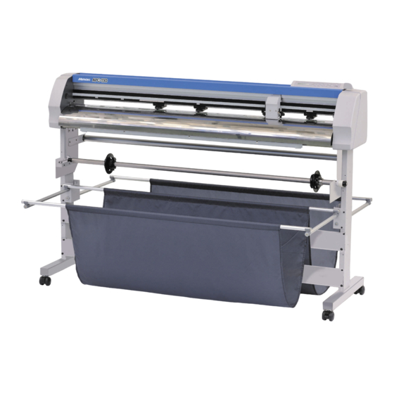
- Page 1 MIMAKI ENGINEERING CO., LTD. URL: http: // www.mimaki. co. jp/ D202229-11 Original instructions...
-
Page 2: Table Of Contents
TABLE OF CONTENS CAUTION ....................vi CAUTION .................... vi Requests ..................... vi FCC Statement (USA) ................. vi Interference to televisions and radios ..........vi Foreword ....................vii On This Operation manual ..............vii Safety Precautions ................viii Pictorial signs ..................viii Safety Labels ..................x How to Read This Operation Manual ..........xi Chapter 1 Before Use... - Page 3 Function by jog mode ...............3-2 Paper cut ...................3-2 Axial correction of two positions ............3-3 Setting cut area .................3-4 Digitizing operation ................3-5 Perform Multiple Cutting (plotting) ............3-6 Investigate the causes of cutting abnormality ........3-7 Cut the sample data “Cut” ..............3-7 Cut the sample data “LOGO” ............3-8 Cut the sample data “RECTANGLE”...
- Page 4 Chapter 5 Appendix Specification ..................5-2 Maintenance ..................5-3 Cleaning the Exterior Surfaces ............5-3 Cleaning the Platen ................5-3 Function Flowchart ................5-4 Function by the dedicated key ............5-4 Function by the jog mode ..............5-5 Functions ...................5-6...
-
Page 6: Caution
• In the case where MIMAKI-recommended cable is not used for connection of this device, limits provided by FCC rules can be exceeded.To prevent this, use of MIMAKI-recommended cable is essential for the connection of this plotter. -
Page 7: Foreword
Read this Operation manual carefully and make the most effective use of your plotter. On This Operation manual • This Operation manual describes the operation and maintenance of APPAREL CUTTING PLOTTER APC-130 (hereinafter referred to as the plotter). • Please read and fully understand this Operation manual before putting the machine into service. It is also necessary to keep this Operation manual on hand. -
Page 8: Safety Precautions
Safety Precautions Pictorial signs Pictorial signs are used in this Operation manual for safe operation and for prevention of damage to the plotter. Pictorial signs and their meanings are given below. Read and fully understand before reading the text. Example of pictorial signs Failure to observe the instructions given with this symbol can result in death or serious injuries to personnel. - Page 9 Safety Precautions Precaution for Use CAUTION Be careful with the movable parts Sheets • Do not touch the rolling grit roller; otherwise, you • Use a strongly curled sheet after removing curl. may hurt your fingers or tear off your finger nails. Heavily curled sheet affects the cutting (plotting) •...
-
Page 10: Safety Labels
Safety Precautions Safety Labels A safety label is stuck on the machine. The label informs the user of possible risks associated with the machine. Be sure to understand the correct meaning of the safety label to avoid danger. If the safety label is illegible due to stains or has come off, purchase a new one from your local distributor or our office. -
Page 11: How To Read This Operation Manual
How to Read This Operation Manual... - Page 13 Chapter 1 Before Use This chapter describes the items required to understand before use, such as the name of each part of the machine or the installation procedures. Installing this machine ..............1-2 Where to install this machine ............1-2 Configuration and function ...............1-3 The Front ..................1-3 The Rear ..................1-4 Operation Panel ................1-5...
-
Page 14: Installing This Machine
Installing this machine Where to install this machine Secure a suitable installation space before assembling this machine. The place of installation must have enough space for not only this machine itself but also for cutting operation. Width Depth Height Gross weight 1825 mm 700 to 1110 mm 1217mm... -
Page 15: Configuration And Function
Configuration and function The Front Tray You can put a small object on it. However, do not put a heavy one. (It may cause the deformation of the cover.) Power switch Operation Panel Turns on/off the power. Use to operate this device and to set each P.2-6) function. -
Page 16: The Rear
The Rear AC inlet Connector for the plotter power cable. P.1-11) Clamp pressure lever Switches the strength of the pressure to hold the sheet. ( P.1-7) USB interface connector. Connect the PC and this machine with the USB interface cable. ( P.1-10) RS-232C interface connector. -
Page 17: Operation Panel
Configuration and function Operation Panel The operation panel is used for each operation. Display panel POWER lamp Displays the tool conditions such as SPEED, PRESS When the power of this device is turned on, and OFFSET, the tool coordinate, each function and the error message. -
Page 18: Carriage
Carriage Pen holder Tool holder Fix a rollerball for plotting. ( P.2-5) Fix a pen-type cutter for cutting. P.2-3) Pinch rollers and grit rollers Align the pinch roller to the width of the sheet to be set, and move it to an appropriate position of the grit roller. Move the pinch roller guessing the “PINCH ROLLER SETTINGS”... -
Page 19: Clamp
Configuration and function Clamp The clamp pressure can be changed in two levels using the clamp pressure lever. Select the higher or lower level of the clamp pressure that matches the sheet to be used. • Use the clamp pressure of clamps at both sides in the same mode (refer to the table below). If you use the clamps at both sides in the different mode, it may cause misalignment of the sheet. -
Page 20: Pen Line
Pen line Cutting and plotting are performed on the pen line. The front side of the pen line is for plotting, and the rear side is for cutting. Pen line Replacing method of pen line When you replace the pen line (Product No.: SPC-0725), follow the procedures below: Turn the clamp lever to the front. - Page 21 Configuration and function Attach a new pen line. • Attach a new pen line in the groove. • The back side of the pen line is a magnet. Making the magnet side back, insert it into the groove. • The pen line is both for cutting (green brush part) and for plotting. For cutting (back side) Be sure to make the part for cutting (green part) back side and attach it.
-
Page 22: Connecting Cables
Connecting USB Interface Cable When you connect with USB interface, it is necessary to install the “USB driver” and the “Mimaki Port Monitor” included in the attached manual CD. • For the “USB driver” and the “Mimaki Port Monitor”, insert the attached manual CD into the host computer, and then click “USB driver setup”... -
Page 23: Connecting The Power Cable
Connecting Cables Connecting the power cable After connecting the interface cable, you must connect the power cable. Connect the power cable with the plug outlet of the following power specifications. • Voltage AC100 to 240V ± 10% • Frequency 50/60Hz ± 1% •... -
Page 24: Menu Mode
Menu mode This plotter is provided with the following four modes: NOT-READY mode The plotter is in this mode until the sheet is detected. The keys other than the key are effective. LOCAL mode The plotter enters this mode after the sheet detection. All the keys are effective. - Page 25 Chapter 2 Basic Operations This chapter describes the procedures and settings ranging from tool installation to cutting (plotting) operation. Operation Flow ................2-2 Installing a tool .................2-3 How to install a cutter ..............2-3 How to install a ballpoint pen ............2-5 Turning the Power ON/OFF .............2-6 Turning the power on ...............2-6 Turning the power off ...............2-6 About Tool Conditions ..............2-7...
-
Page 26: Operation Flow
Operation Flow Installing a tool See “Installing a tool” ( P.2-3). Turning the power on See “Turning the power on” ( P.2-6). About Tool Conditions See “About Tool Conditions” ( P.2-7). Installing a Roll Sheet See “Installing a Roll Sheet” ( P.2-11). -
Page 27: Installing A Tool
Installing a tool For this device, attach both of a cutter to cut patterns and a pen (a rollerball) to plot characters. How to install a cutter • Do not touch the cutter blade, which is very sharp. The sharp blade edge of the cutter may cause you to get injured. •... - Page 28 How to install the cutter holder Attach the cutter holder on the tool holder of the carriage. • Install the cutter holder to the tool holder of the carriage.Be sure to insert the cutter holder all the way in the tool holder. Rotate the knob to loosen the holder presser.
-
Page 29: How To Install A Ballpoint Pen
Installing a tool How to install a ballpoint pen Insert a spring into the pen tip. While pressing the cap onto the spring, attach it on the pen adapter. • Rotate the cap to the direction indicated with an arrow and attach it on the pen adapter. -
Page 30: Turning The Power On/Off
Turning the Power ON/OFF Turning the power on • Before turning the power on, check that the pinch rollers have been raised. • Be sure to turn on the host computer before turning on the plotter. If this order is not correctly followed, the plotter can malfunction. -
Page 31: About Tool Conditions
About Tool Conditions You can register the cutting speed and the pressure depending on the sheet or the tool type to be used. (Tool condition) Kinds of the Tool Conditions A tool condition consists of cutting conditions (CUT1 to CUT7), printing-with-a-pen condition (PEN). Kinds Description This is a tool condition when a cutter is used. -
Page 32: Select The Tool Condition
Select the tool condition Before cutting (plotting), select the tool condition depending on the sheet and the tool type to be used. Press the key in LOCAL mode. C U T 1 0 5 0 0 . 3 0 Press the key to select a tool condition to be used. - Page 33 About Tool Conditions Press to move the cursor to OFFSET. C U T 2 0 8 0 0 . 3 Press to set the offset value . C U T 2 0 8 0 0 . 3 Cutter • When you set the cutting condition (CUT1 to 7), set the distance holder between the center of the cutter holder and the blade tip.
- Page 34 About Tool Conditions Press the key to register the set contents. • Return to the local mode. • The set value is retained even when the power is turned "OFF". Reference for cutting condition Depending on the sheet type to be used, it is required to change the setting value of the cutting condition. Below is the reference for the cutting condition.
-
Page 35: Installing A Roll Sheet
Installing a Roll Sheet About Roll Sheet Usable sheet sizes and notes for handling are described. Usable Sizes of Sheet Type of recommended sheet Pattern for apparel product Maximum width 1400mm Minimum width 890mm Maximum cut range 1240mm × 3000mm Thickness 64 to 180g/m Roll outside diameter... -
Page 36: Set A Roll Sheet
Set a roll sheet Loosen Insert the roll holder (one) into the roll bar. (1) Loosen the roll set screw of the roll holder. • Be careful not to loosen the roll set screw too much. If you loosen it too much, the roll holder may be broken down. - Page 37 Installing a Roll Sheet Put another roll holder into the roll bar through, and fix the roll sheet. (1) Loosen the roll set screw of another roll holder. • Be careful not to loosen the roll set screw too much. If you loosen it too much, the roll holder may be broken down.
- Page 38 Move the clamp lever to the front to move the pinch roller upward. Go to the rear of this device and pull out the sheet. Insert the sheet between the pinch roller and the Pinch roller grid roller as indicated to put it through to the front Grit roller side of this device.
- Page 39 Installing a Roll Sheet Align the right edge of the sheet set on the roll bar with the right edge of the sheet pulled out. While holding the center part of the sheet, rotate the roll holder to the rear side and tighten the sheet.
- Page 40 About sheet detection When you move the clamp lever to the rear side with the power of this device ON, the device enters in the sheet detection mode. There are two types of sheet detection. Normal detection Sheet width detection After the sheet width was detected, detects the sheet front Only detects the sheet width.
-
Page 41: Attach The Sheet Basket
Installing a Roll Sheet Attach the sheet basket Attach the sheet basket to prevent the cut (plotted) result from being stained. Attach the sheet basket both on the front side and the rear side of this device. Remove the cap of the attached basket bars (x 4) (only one side). - Page 42 Insert the pipes (x 2) into the pipe inserting parts of the attached fabric and prepare the sheet basket for front side. • There are three pipes to be used for the sheet basket. Here, insert the pipe to be used for the sheet basket in front side.
-
Page 43: Set The Pinch Roller
Installing a Roll Sheet Set the pinch roller Adjust the setting position of the pinch rollers (1 to 4) depending on the sheet size to set. If the pinch roller is not set properly, the sheet may be fed at a slant and it may cause sheet jam etc. Slide the pinch roller to right and left to arrange it in the proper position. - Page 44 Installing a Roll Sheet About available area for cutting You can cut (plot) in the following area. Available area for cutting Pinch roller (Arrange evenly.) 2-20...
-
Page 45: Test Cutting
Test Cutting Test cutting is performed to check whether the settings for tool conditions are appropriate. In test cutting, two squares shown right are cut. • To perform test plotting, it is required to set half cut of cutting condition to “ON”. -
Page 46: Cutting (Plotting)
Cutting (plotting) When attaching the sheet/ the roll sheet and setting of tool condition are completed, perform cutting (plotting). Before cutting (plotting), check the following setting: • Origin setting ( P.2-22) • Setting the ORIGIN SELECT ( P.3-19) • Setting the COMMAND ( P.3-16) •... -
Page 47: Starting A Cutting Operation
Cutting (plotting) • Pay attention to the expansion and contraction of the roll sheet. The sheet can be affected by the room temperature and humidity, and thus it may expand and contract. Before cutting (plotting), using the pre-feed function, acclimate the sheet to the work environment enough. -
Page 48: Starting A Plotting Operation
• Pay attention to the expansion and contraction of the roll sheet. The sheet can be affected by the room temperature and humidity, and thus it may expand and contract. Before cutting (plotting), using the pre-feed function, acclimate the sheet to the work environment enough. -
Page 49: Stopping A Cutting (Plotting) Operation (Data Clear)
Cutting (plotting) Suspension of cutting (plotting) When you suspend cutting (plotting), press the key once. When you press once more, cutting (plotting) starts again. • When you perform the function with the operation or the operation to affect the command coordinate during suspension, an error message is displayed. - Page 50 2-26...
- Page 51 Chapter 3 Extended Functions This chapter describes the setting procedures of each functions, and how to operate the plotter usefully. Function by jog mode ........3-2 Setting the PRIORITY ........3-23 Setting the SHEET SENSOR ....3-24 Paper cut ............. 3-2 Setting the UP SPEED ......3-25 Axial correction of two positions ....
-
Page 52: Function By Jog Mode
Function by jog mode When you press the jog keys in the local mode, the device enters into the jog mode. You can set each setting below in the jog mode. Reference Function Name Meaning Page Origin setting Sets the position to start cutting (plotting). P.2-22 Paper cut (Cutting off) Cuts off the sheet on the current tool position. -
Page 53: Axial Correction Of Two Positions
Function by jog mode Axial correction of two positions Correction When you set the sheet such as a graph paper with the vertical line and the point horizontal line, aligns the vertical axis and the horizontal axis with these lines. Correct the axis slope (θ) with the set origin and the correction point. -
Page 54: Setting Cut Area
Setting cut area The cut area can be set within the area from the origin to the Point Point UL UL (Upper Left), any point set on the diagonal. Here, set the Point UL position. When you perform sheet detection again, cut area is cleared. area Origin Press the... -
Page 55: Digitizing Operation
Function by jog mode Digitizing operation The coordinate from the origin of the plotted shape is displayed on the host computer. When you receive the digitizing command (DP;) from the host computer, the digitizing operation becomes usable. For digitizing, attach the sheet with design to specify the point. •... -
Page 56: Perform Multiple Cutting (Plotting)
Perform Multiple Cutting (plotting) Already received data can be copied (plotted with a pen) to produce a multiple number of pieces of data. (Up to 999 pieces) • Copying of data to produce a multiple number of pieces of data is performed with the data stored in the machine's reception buffer being specified. -
Page 57: Investigate The Causes Of Cutting Abnormality
Investigate the causes of cutting abnormality In such a case as when data cannot be cut normally, a sample stored in this machine is cut to check the cause of the abnormality. (Sample Cut) There are three samples that you can cut: Sample type Overview Use this when you cannot cut even if the machine has received... -
Page 58: Cut The Sample Data "Logo
Cut the sample data “LOGO” Press the key in LOCAL mode. S Q U A R E C U T < E N T > Press to select [SAMPLE CUT]. S A M P L E C U T < E N T > Press the key. -
Page 59: Cut The Sample Data "Rectangle
Cut the sample data “RECTANGLE” Press the key in LOCAL mode. S Q U A R E C U T < E N T > Press to select [SAMPLE CUT]. S A M P L E C U T < E N T > Press the key. -
Page 60: Distance Correction
Distance correction When you cut the long data, the cut length may have difference depending on the sheet thickness. In addition, depending on the difference of the grid roller diameter, the moving amount of right and left of the sheet may have difference. - Page 61 Distance correction Pressing , select the distance correction N o . 3 A R = 1 . 0 0 0 0 0 number to register. Press the key. = 5 0 0 B = 2 0 0 • The standard length (mm) that was corrected previous time is displayed.
- Page 62 Distance correction Actually measure OFF lines of AR, AL and B. • Move the clamp lever to the rear side, remove the sheet and measure. Perform the operations in Steps 2 to 13. • As the sheet is not set, the correction entry screen is displayed without performing plotting. If the measured value is different from the standard R = 1 .
-
Page 63: Sheet Feed
Sheet feed Before you start cutting or plotting with a pen, feed a certain length of the media to allow a margin. By feeding the sheet beforehand, you can check for a skew of the sheet or prevent a skew while cutting the long data (or printing the long data with a pen). -
Page 64: Hold
Hold If the sheet becomes misaligned during cutting (plotting) long Data after the data, you can adjust it by suspending cutting (holding). correction of sheet displacement. • When you adjust the sheet misalignment, do not Cut before the sheet misalignment is move the position of the carriage and the pinch fixed. -
Page 65: Setting Function
Setting function To use this device more comfortably, you can change the setting depending on your usage. In the setting function, you can set the following items: Reference Function Name Overview Page Depending on the command specification of the host computer side, switches the COMMAND P.3-16 command. -
Page 66: Setting The Command
Setting the COMMAND Switches commands depending on the command specification of the host computer side. Set Value Overview AUTO Switches to MGL-lc1 or MGL-llc automatically depending on the command of received data. Used when receiving the data of MGL-lc1 command. MGL-Ic1 Used when receiving the data of MGL-llc command. -
Page 67: Setting The Interface
Setting function Setting the INTERFACE Set the communication conditions for RS-232C interface connection (connection condition, command coordinate resolution, data judgment time and data end command). Set Item Set Value BAUD RATE 1200, 2400, 4800, 9600, 19200, 38400 (bps) DATA BITS 7, 8 (bit) PARITY NON, EVEN, ODD... -
Page 68: Setting The Device No
Repeat the procedures of the Step 6 and 7 to set other setting items. • Perform the same operations as in Steps 6 and 7 to set all items. Press the key. Press the key several times to end the setting. •... -
Page 69: Setting The Origin Select
Setting function Setting the ORIGIN SELECT Sets the origin position with MGL-llc command. Set Value Overview CENTER ORIGIN Sets the origin at the center of the available cutting area. Sets the origin at the lower right of the available cutting area (lower right of AB coordinate). LOWER RIGHT ORIGIN •... -
Page 70: Setting The Auto Cut
Setting the AUTO CUT Performs the setting to cut off the sheet automatically after cutting is completed. When the automatic cutting is set to “ON”, you must set the cutting pressure and the cutting speed. Set Item Set Value Overview Set the pressure for cutting off the sheet. -
Page 71: Setting The Rotation
Setting function Press to set the extra pressure added to C U T P R E S S 8 0 g the normal cutting pressure. • Setting value : 0 to 400g Press the key. S L A N T C U T 5 mm Press... -
Page 72: Setting The Buzzer
Press to select [ROTATION]. R O T A T I O N < e n t > Press the key. R O T A T I O N : O N Press to select ON/OFF. R O T A T I O N : O F F Press the key. -
Page 73: Setting The Priority
Setting function Press the key. Press the key several times to end the setting. • The set value is retained even when the power is turned "OFF". Setting the PRIORITY Set which has priority, the set value of this device (panel) or the set value of the host computer (host). •... -
Page 74: Setting The Sheet Sensor
Repeat the procedures in the Step 6 and 7 to set other commands. • Perform the same operations as in Steps 6 and 7 to set other items. Press the key. Press the key several times to end the setting. •... -
Page 75: Setting The Up Speed
Setting function Press the key. S H E E T S E N S O R : O N Press to select ON/OFF. S H E E T S E N S O R : O F F Press the key. -
Page 76: Setting The Jog Step
Press the key several times to end the setting. • You can set the up speed during data cutting higher than the cutting speed. However, after any cutting operation is performed, for the stable sheet feeding, the speed is limited to the cutting speed. •... -
Page 77: Setting The Mm/Inch
Setting function Setting the MM/INCH Switch the unit to display the length from mm to inch. • The jog moving unit and the sheet size display are changed. Press the key in LOCAL mode. S Q U A R E C U T <... -
Page 78: Setting The Pre Feed
Setting the PRE FEED Perform next setting about automatic paper feeding after sheet detection or automatic cutting. Set Item Overview Set Value Sets the feed length of the sheet. By feeding the sheet by the amount to be cut (plotted) in advance, as the Feed length 0.1 to 3 m sheet can adjust itself to the work environment, cutting (plotting) quality can... -
Page 79: Setting The Feed Offset
Setting function Press the key. Press the key several times to end the setting. • The set value is retained even when the power is turned "OFF". Setting the FEED OFFSET You can perform extra feeding when performing automatic feeding and pre-feeding of the sorting function. By performing extra feeding, you can ensure slack required for cutting (plotting). -
Page 80: Setting The Dummy Cut
Setting the DUMMY CUT The “DUMMY CUT” is performed to make the blade tip faces a certain direction before starting cutting. Pinch roller When you perform the followings, the dummy cut operation is performed. • When you selected the tool (CT1 to CT7) DUMMY CUT •... -
Page 81: Setting The Sheet Type
Setting function Setting the SHEET TYPE When using a heavy (thick) sheet or a wide sheet, change the sheet setting to prevent the sheet misalignment. • When you set the [SHEET TYPE] to [THICK], the max. speed is limited to 20cm/s. •... -
Page 82: Setting The Sorting
Setting the SORTING By changing the order of pieces of data for cutting transmitted from the host computer, you can change the order of cutting them. (Sorting function) When data to be cut with a single stroke cannot be cut with a single stroke because of the order of pieces of data transmitted from a software application, you can cut the data with a single stroke by changing the order of cutting them. - Page 83 Setting function Setting the SORTING Press the key in LOCAL mode. S Q U A R E C U T < E N T > Press to select [SET UP]. S E T < E N T > Press the key.
- Page 84 Cancelling the Setting of the SORTING Perform the operations in Steps 1 Press Press the Press to 5 in "Setting the select "OFF". twice. Sorting Function". Procedure for SORTING Transmit data. C U T 1 2 K B • The size of the data that has not been processed yet in the reception buffer is displayed. Cutting (plotting with a pen) is not performed.
-
Page 85: Setting The Over Cut
Setting function Setting the OVER CUT OVER CUT:OFF Specify whether the over cutting function is enable or unable and the length of the over cutting. If the length of the over cutting is set, cutting is performed with extra cutting space at the front by the specified amount of length at the start of cutting and tool up is performed at the end going too far. -
Page 86: Setting The Start Mode
Setting the START MODE Set the mode after the sheet was detected. Set Value Overview LOCAL Enters in the waiting status in the local mode after the sheet was detected. REMOTE Enters in the remote mode automatically after the sheet was detected. Press the key in LOCAL mode. -
Page 87: Setting The Ip X Distance
Setting function Setting the IP x Distance Set the scaling point (IP). • When a dotted line becomes a solid line etc., perform this setting. • The setting of roll paper IP x distance is valid for MGL-llc command. Press the key in LOCAL mode. -
Page 88: Setting The Nr!Pg Change
Setting the NR!PG CHANGE You can replace the NR of MGL-llc command with !PG. When you output data continuously using CAD outputting NR at the data end, set this to prevent from transferring to the view mode by NR. Press the key in LOCAL mode. -
Page 89: Setting The Pen No. Assign
Setting function Setting the PEN No. ASSIGN Allocate the cutter (pen) number (SP command) sent from the host computer when performing cutting (plotting) to the cutter (pen) number of this device. • The pen No. assign setting is valid for MGL-llc command. Press the key in LOCAL mode. -
Page 90: Setting The Tool Change
Setting the Tool Change The carriage of this device has both tolls of a cutter for cutting and a pen for plotting. Depending on your use, perform cutting (plotting) by switching a cutter to a pen. Here, perform setting related to the switching operation of the cutter and the pen. Set Item Set Value Overview... -
Page 91: Initializing The Settings
Setting function Press to select a set value. S P E E D Set Value: 1 to 30 cm/s Press the key. Press the key several times to end the setting. • The set values are recorded even when the power has been turned OFF. Initializing the Settings Press the key in LOCAL mode. -
Page 92: Output The Setting List
Output the setting list Keep the list as the record or to fax for inquiry on the maintenance. Mount the sheet. ( P.2-11) Press the key in the local mode to select the P E N 0 6 0 plotting condition (PEN). •... -
Page 93: Output The Received Data In The Ascii Code
Output the received data in the ASCII code After the host computer sends data and the communication condition of the interface that receives data is plotted, plot data in the ASCII code (ASCII dump). The ASCII dump can be performed in the interface with which the host computer is connected. Mount the sheet. -
Page 94: Switch The Language Display On The Screen
Switch the language display on the screen You can choose the language displayed on the screen from seven types. (Default is "English".) Selectable language : Japanese, English, German, French, Spanish, Italian, Portuguese Press the key in LOCAL mode. S Q U A R E C U T <... - Page 95 Chapter 4 Troubleshooting This chapter describes the actions to be taken when the plotter develops any trouble or displays an error message. Troubleshooting ................4-2 Warning/Error Messages ..............4-4 Error Messages ................4-4 Warning Messages ................4-6...
-
Page 96: Troubleshooting
Troubleshooting When you feel that the device is broken, first refer to the items below: If the problem is still not solved after troubleshooting, contact your distributor or our service office. Failure phenomenon Cause Solution The power cable of the machine is Securely connect the power cable Power does not turn ON. - Page 97 Troubleshooting Failure phenomenon Cause Solution Attach it so that the sheet is not The sheet is warped. warped. Turn the power OFF and try to lift/ lower the tool holder by hand. The tool is dragged during The tool does not move up/down If the tool holder does not move up operation.
-
Page 98: Warning/Error Messages
Warning/Error Messages Error Messages The error message displays the error number. Even if you perform the measure for the displayed error number, contact a distributor in your district or our office to call for service. Messages Cause Solution An error occurred in the control RAM. E R R 0 2 M A I N R A M . - Page 99 Warning/Error Messages Messages Cause Solution Improper operation was conducted Press the key to cut data, or while cutting suspended E R R 3 4 D A T R E M A I N perform data clear. ( P.2-25) REMOTE. The motor to feed the sheet became Perform the following works.
-
Page 100: Warning Messages
Warning/Error Messages Warning Messages These are the message displayed in the remote mode. As this does not indicate the device breakdown, take the proper measure as required. Messages Cause Solution When you press the key, the The remote mode is selected. C U T 1 R E MO T E screen returns to LOCAL. - Page 101 Chapter 5 Appendix This chapter describes the replacement procedure for the cutter blade and the specifications of the plotter. Specification ..................5-2 Maintenance ..................5-3 Cleaning the Exterior Surfaces ............5-3 Cleaning the Platen .................5-3 Function Flowchart ................5-4 Function by the dedicated key ............5-4 Function by the jog mode ..............5-5 Functions ..................5-6...
-
Page 102: Specification
Specification Item Specification Type of sheet Roll paper (for apparel 64 to 180g/m Sheet width 890 to 1400mm Settable Roll inside sheet 200mm or less diameter Weight 20kg or less Available area for cutting 1240mm x 3000mm Maximum speed 141cm/s (at plotting, pen moving upward 45 degree direction) Plot : Max.60cm/s settable speed... -
Page 103: Maintenance
Maintenance Cleaning the Exterior Surfaces When the exterior surfaces of the machine are stained, dampen a soft cloth with water or a neutral detergent diluted with water, squeeze it, and wipe the surfaces with the cloth. Cleaning the Platen The platen easily gets dirty with paper dust, etc. generated when a sheet is cut. Wipe off conspicuous dusts with a dry cloth, a paper towel, etc. -
Page 104: Function Flowchart
Function Flowchart Function by the dedicated key REMOTE key C U T 1 0 5 0 0 . 3 0 C U T 1 R E M O T E LOCAL mode REMOTE mode FEED key C U T 1 0 5 0 0 . -
Page 105: Function By The Jog Mode
Function by the jog mode Origin setting method C U T 1 0 5 0 0 . 3 0 0 . 0 0 . 0 5 . 0 1 0 . 0 LOCAL mode O R I G I N A = * * * * B = * * * * Paper cutting method... -
Page 106: Functions
Functions Start test cutting. CU T 1 2 0 0 5 0 0 . 3 0 SQUARE CU T < EN T > COP Y < EN T > COP Y 1 to 999 D I S T . COMP . <... - Page 107 Function Flowchart Select the distance correction No. A = 5 0 0 B = 2 0 0 A = 1 0 0 0 B = 2 0 0 Select the standard value of the A direction. Select the standard value of the B direction. Plotting pattern Measuring line segment DRAW SH I F T = 1 0 mm...
- Page 108 From P.5-6 From P.5-6 PR I OR I T Y < e n t > SHE E T s e n s o r < e n t > UP S P E ED < e n t > J OG S T E P <...
- Page 109 Function Flowchart : HOS T : HOS T : HOS T HOST, PANEL HOST, PANEL HOST, PANEL : HOS T : HOS T : HOS T HOST, PANEL HOST, PANEL HOST, PANEL : HOS T HOST, PANEL SHE E T S ENSOR : OF F ON/OFF UP S P E ED : AU TO...
- Page 110 From P.5-8 From P.5-8 NR - > ! PG CHG < e n t > P EN N o . A S I GN e n t > T o o l C h a n g e < e n t > S E T UP RE S E T <...
- Page 111 Function Flowchart N R - > ! P G C H G : O N ON/OFF S P 1 : n = 1 2 3 4 5 6 7 8 CHECK : ON RE T RY : OF F S P E ED ON/OFF ON/OFF 1 to 30 cm/s...
- Page 112 5-12...
- Page 113 APC-130 Operation Manual March, 2012 MIMAKI ENGINEERING CO.,LTD. 2182-3 Shigeno-otsu, Tomi-shi, Nagano 389-0512 JAPAN D202229-11-02032012...
- Page 114 © MIMAKI ENGINEERING CO., LTD.2011 FW : 1.2...
Need help?
Do you have a question about the APC-130 and is the answer not in the manual?
Questions and answers