Table of Contents
Advertisement
Quick Links
For safe operation ........................................................... 2
Pictorial signs ............................................................................................ 2
Example of pictorial signs ......................................................................... 2
Precautions in installation .......................................................................... 5
Precautions in use ...................................................................................... 6
Precautions in handling the ink cartridge .................................................. 8
Where to Install the Device ............................................ 9
Unpacking and Assembling ......................................... 10
Assembling the pedestals and the device ................................................ 10
Mounting the protection cover for 440cc ink cartridges ......................... 15
Assembling Rear Exhaust Duct ............................................................... 17
Assembling drier fan Unit ....................................................................... 18
Assembling Front Exhaust Unit .............................................................. 19
Leading the exhaust hose to the left ........................................................ 24
If the roll screen spring has lost its elasticity .......................................... 25
Setting the heater voltage ............................................ 26
Connecting the Cables ................................................. 27
Connecting the interface cable ................................................................ 27
Connecting the power cable .................................................................... 28
Turning the power ON ................................................... 29
Filling Ink for First Time ................................................ 30
Turning the power OFF ................................................. 31
Accessories ................................................................... 32
TKB Gotenyama Building, 5-9-41, Kitashinagawa, Shinagawa-ku, Tokyo 141-0001, Japan
Phone: +81-3-5420-8671
Table of contents
Fax: +81-3-5420-8687
URL: http: // www.mimaki. co. jp /
E-mail: traiding@mimaki.co.jp
Setup Guide
D200926
Advertisement
Table of Contents

Related Manuals for MIMAKI JV3-160SP


Summary of Contents for MIMAKI JV3-160SP
-
Page 1: Table Of Contents
Filling Ink for First Time ..........30 Turning the power OFF ..........31 Accessories ..............32 MIMAKI ENGINEERING CO., LTD. TKB Gotenyama Building, 5-9-41, Kitashinagawa, Shinagawa-ku, Tokyo 141-0001, Japan Phone: +81-3-5420-8671 Fax: +81-3-5420-8687 URL: http: // www.mimaki. co. jp / E-mail: traiding@mimaki.co.jp D200926... -
Page 2: For Safe Operation
For safe operation Pictorial signs Pictorial signs are used in this Instruction Manual for safe operation of and in prevention of damages to the device. Pictorial signs and their meanings are given below. Read and fully understand before reading the text. •... - Page 3 WARNING • Be sure to setup the appropriate air-moving system in case of using the device in a closed room or a room with bad ventilation. • The special ink used for the device contains organic solvent (cyclo- hexanone), Since the ink is flammable, never use fire when using the device.
- Page 4 • Never refill the ink cartridge with ink. from the receptacle. Check first to be MIMAKI assumes no responsibility sure that the device no longer for malfunction caused by using the produces smoke, and contact a device after replenishment of ink.
-
Page 5: Precautions In Installation
Precautions in installation CAUTION A place that is not horizontal A place exposed to direct sunlight A place in which temperature and humidity A place that vibrates vary by a great margin Use the device under the following environment. Operating environment: 15 to 30°C 35 to 65% (Rh) A place exposed to direct air blow from air... -
Page 6: Precautions In Use
When • Store media in a bag. Wiping off dust moving it to a different place, contact accumulated on a media will Mimaki sales office or dealer. adversely affect the media due to static electricity. Use the ink specified •... - Page 7 CAUTION • Be sure to store ink cartridges in a Locking the casters cold and dark place. • Be sure to lock the casters before • Never replenishes the ink cartridge starting plotting. If the device with ink. performs plotting without the casters locked, the device can move out of position.
-
Page 8: Precautions In Handling The Ink Cartridge
• Never refill the ink cartridge with ink. Refilling the ink cartridge can cause a trouble. Remember that Mimaki assumes no responsibility for any damage caused by the use of the ink cartridge replenished with ink. -
Page 9: Where To Install The Device
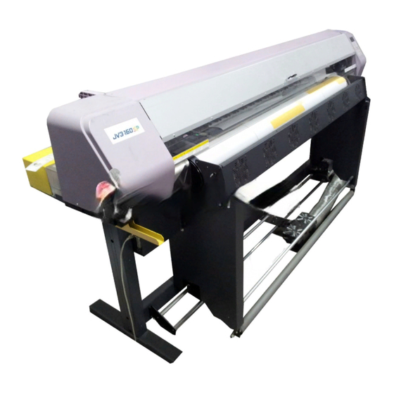
The place of installation must have space required not only for the device itself but also for plotting operation. Model Width Depth Height Gross weight JV3-160SP 2660 mm 750 mm 1240 mm About 175kg* *: With exhaust unit : 185kg 500 mm... -
Page 10: Unpacking And Assembling
Unpacking and Assembling Assembling the pedestals and the device • The pack of the device is as heavy as approximately 200 kg. Perform the assembly work by at least four persons to ensure safety. • Exercise added care not to drop the main unit on your feet. 1. - Page 11 Using four screws, attach the stay to the leg tempo- Stay rarily. The stay has vertical and horizontal aspects. The side of the leg with a ditch is the outside. Use the hexagonal wrench. Ditch Temporality tighten Lock the four stoppers of the leg. Hold the handles of the plotter by four people.
- Page 12 Put the front face of the leg first. If the rear face of the leg is put first, the plotter cannot be attached because of the interface connectors. The plotter is very heavy. Be careful not to • drop it. IEEE 1284 interface Fix the plotter and stay to the leg.
- Page 13 10. Remove two screws each from the right and left sides and detach the right and left handles. 11. Remove the four screws which fix the take-up device to the plotter. Then, attach the take-up device to the stay. 12. Connect the cable of the take-up device to the con- nector at the bottom of the plotter.
- Page 14 13. Attach the waste ink tank bracket to the plotter. 14. Attach the waste ink tank tray with four screws. 15. Attach the waste ink tank. 16. Open the front cover and then remove the sponges. Remove the two screws and then remove the head stopper.
-
Page 15: Mounting The Protection Cover For 440Cc Ink Cartridges
Mounting the protection cover for 440cc ink cartridges Remove the two knobs and the ink name plate. When insert the ink cartridge, remove the ink cartridges from ink station. Remove the two knobs at side of the ink station. • Keep the knobs for mounting the 440cartridge base. - Page 16 6. Set the two protection covers on 440 cartridge base. Insert the protection cover between the 440 car- tridge base and the screws that fixed temporarily in procedure5. Tighten the screws to mount the protection cover. 7. Mount the protection cover at the both side of ink station as the same way.
-
Page 17: Assembling Rear Exhaust Duct
Assembling Rear Exhaust Duct duct Attach the duct to the rear panel of the plotter using three screws. The duct can be attached either rightward or leftward depending on the exhaust outlet ventilation. hose band Fix the exhaust hose using hose band. Lead the opposite end of the hose outdoors. -
Page 18: Assembling Drier Fan Unit
Assembling drier fan Unit 1. Attach the drier fan stay R/L to the front panel of the plotter using 4 screws. 2. Attach the drier fan unit to the fan stay using 2 supporting point screws. 3. Attach 2 knob screws. 4. -
Page 19: Assembling Front Exhaust Unit
Assembling Front Exhaust Unit • Wear protective gloves when assembling the front exhaust unit. If you do not wear gloves, you may get hurt. • Be sure to perform step 7) to pull out the pin which fixes the winding of the roll screen. - Page 20 3. Attach the exhaust cover R to the drier fan stay R and leg stay using 3 screws. 4. Attach the exhaust cover L to the drier fan stay L and leg stay using 3 screws. 5. Attach the exhaust cover stay to the exhaust cover R/L using 2 screws.
- Page 21 Insert fixed plate L at the left end of the roll screen. Note the mounting orientation of the roll screen. fixed plate L Roll screen • If the spacing between the right and left fixing plates are too narrow, loosen the two bolts fixing the roll screen locking plate.
- Page 22 8. Extract the roll screen shaft from the roll screen with long-nose pliers. • The pin is needed to detach the roll screen. Be careful not to lose the pin. 9. Lead the exhaust hose under the exhaust cover. Attach it to the exhaust fan using hose bands. •...
- Page 23 11. During plotting, hang the screen bar to the exhaust cover. - 23 -...
-
Page 24: Leading The Exhaust Hose To The Left
Leading the exhaust hose to the left When leading the exhaust hose to the left, change the direction of the exhaust fan. 1. Remove the two screws. 2. Change the direction of the exhaust fan so that the exhaust hose will come to the left side. Fix the exhaust fan with two screws. -
Page 25: If The Roll Screen Spring Has Lost Its Elasticity
If the roll screen spring has lost its elasticity If the knob at the right end of the screen is released without sticking the pin, the screen take-up spring will be stretched. Once stretched, the screen will lose its elasticity to take up the screen. If the elasticity has been lost, wind the spring again as shown below Pull the end of the screen about 12 inches out. -
Page 26: Setting The Heater Voltage
Setting the heater voltage Set the heater voltage according to the supply voltage to the plotter. For the voltage setting, use the three voltage selectors under the left back of the cover. At shipping from the factory, the voltage is set to 220 V for safety. •... -
Page 27: Connecting The Cables
Connecting the Cables Connecting the interface cable Connect the device to the computer with the appropriate interface cable. Two types of interface cables are available with the device. Select the interface cable appropriate to the computer and output software used. When Windows 2000/XP is used (IEEE 1394) When the computer is operated with Windows 2000/XP, use an IEEE 1394 interface cable to connect the computer and the device together. -
Page 28: Connecting The Power Cable
Connecting the power cable Connect the power cable as described below. Connect the power cable to the receptacle of the following specifications. • Voltage AC 100 – 120 V ± AC 200 – 240 V ± • Frequency 50/60 Hz ±... -
Page 29: Turning The Power On
Turning the power ON Turn ON the power of the plotter. Push the power switch on the front panel of the plotter once. The switch is pushed in. Turn ON the main power of the plotter. Set the power switch on the rear panel of the plotter to the I side. The main power is turned ON. -
Page 30: Filling Ink For First Time
Filling Ink for First Time To fill up the ink for the first time, pre-fill up solution cartridges. Follow the procedures below to fill up the ink. STEP 1. Turn on the power to the device. PLEASE WAIT 2. Select the ink type (ink set) to fill up pressing the INK TYPE Sol - 4 Color JOG [ ] , [ ] key, and press the [ENTER] key. -
Page 31: Turning The Power Off
Turning the power OFF To turn the power off, check first whether or not there is data received and there remains data that has not yet been output in the device. Also be sure that the head rests at the capping station. •... -
Page 32: Accessories
Accessories Pre-fill up solution cartridges 8 pcs. Goggle Waste ink tank Rear duct hose Hose band Duct, Screws 3 pcs. Waste ink tank bracket, Waste ink tank tray Binding bands 2 pcs. Bolts 8 pcs. screws 2 pcs. screws 4 pcs. (For legs) Power cable Hexagonal wrench... - Page 33 Screws 4 pcs Supporting point screws 2 pcs Knob screws 2 pcs (for Drier fan) (for Drier fan unit ) (for Drier fan) 440 cartridges base 2 plate Protection cover set x2 Knobs 18pcs (for protection cover) Cleaning solution RS kit for maintenance Pipette Gloves 3 pairs Swabs...
-
Page 34: Mimaki Engineering Co., Ltd
Printed in Japan D200926-1.10-11112004 © MIMAKI ENGINEERING Co., Ltd. 2004...
Need help?
Do you have a question about the JV3-160SP and is the answer not in the manual?
Questions and answers