
Related Manuals for Siemens SINAUT MD720-3


Summary of Contents for Siemens SINAUT MD720-3
-
Page 1: Table Of Contents
Preface, Contents SIMATIC NET GPRS/GSM-Modem Introduction SINAUT MD720-3 Inserting the SIM card System manual Connecting the device and switching on the device SINAUT MD720-3 in Terminal Mode SINAUT MD720-3 in OPC Mode Service function Technical Data Glossary C79000-G8976-C211 Release 06/2006... - Page 2 Trademarks All names identified by ® are registered trademarks of the Siemens AG. The remaining trademarks in this publication may be trademarks whose use by third parties for their own purposes could violate the rights of the owner.
-
Page 3: Sinaut Md720-3
The SINAUT MD720-3 may be powered only by power supply units according to IEC/EN60950 section 2.5 "Limited power sources". The power supply unit to supply the SINAUT MD720-3 must comply with NEC Class 2 circuits as outlined in the National Electrical Code (ANSI/NFPA 70) only. - Page 4 When installing an antenna outdoors it is essential that the antenna is fitted correctly by a qualified person. Lightning Protection Standard VDE V 0185 Sections 1 to 4, in its current version, and further standards must be observed. SINAUT MD720-3 C79000-G8976-C211...
- Page 5 Increase the separation between the equipment and receiver. • Connect the equipment into an outlet on a circuit different from that to which the receiver is connected. • Consult the dealer / installer or an experienced radio/TV technician for help. SINAUT MD720-3 C79000-G8976-C211...
- Page 6 You may only use the SINAUT MD720-3 with an antenna of the SINAUT MD720-3 accessory program. The installation of the SINAUT MD720-3 and the antenna as well as servicing is to be performed by qualified technical personnel only. When servicing the antenna, or working at distances closer than those listed below, ensure the transmitter has been disabled.
-
Page 7: Preface
Purpose of this documentation This documentation will support you on your way to successful application of SINAUT MD720-3. It will introduce you to the topic in clear and straightforward steps and provide you with an overview of the hardware of the SINAUT MD720-3 GSM/GPRS modem. - Page 8 Preface Do you still have questions relating to the use of the products described in the manual? If so, then please talk to your local Siemens contact. You will find the addresses in the following sources: • On the Internet at: http://www.siemens.com/automation/partner •...
- Page 9 Introduction........................11 Inserting the SIM card ....................13 Connecting the device and switching on the device ..........19 SINAUT MD720-3 in Terminal Mode................23 Terminal mode activation................... 23 Operating requirements in Terminal Mode: GPRS subscriber contract .... 24 Functions of the LEDs in Terminal Mode ............24 Terminal mode operation...................
- Page 10 Contents SINAUT MD720-3 C79000-G8976-C211...
-
Page 11: Introduction
The change between OPC Mode and Terminal Mode (refer to page 23 or page 58) forces a restart of the device. Terminal mode The SINAUT MD720-3 establishes radio data connections via a GSM network (Global System for Mobile Communication). •... - Page 12 Introduction OPC-Modus The SINAUT MD720-3 transmits data over via a GSM radio network (Global System for Mobile Communication). using GPRS (General Packet Radio Service) between S7-200 devices and an OPC server SINAUT MICRO SC, using SMS from a S7-200-device to any remote station, which can receive SMS.
-
Page 13: Inserting The Sim Card
1. Make sure that the device is disconnected from the supply voltage. 2. The SINAUT MD720-3 must be opened to insert the SIM card. The housing is fastened by two clamps, one on top of the housing and one on the bottom side (see figure 2-1). - Page 14 2-2 4. Remove the rear section of the housing (see figure 2-3). figure 2-3 5. The SIM card holder is visible on the motherboard. (see figure 2-4). SIM card holder figure 2-4 SINAUT MD720-3 C79000-G8976-C211...
- Page 15 7. Raise the flap of the SIM card holder so that you can insert the SIM card. (see figure 2-6). figure 2-6 8. In figure 2-7, the compartment into which you can insert the SIM card is emphasized in white. figure 2-7 SINAUT MD720-3 C79000-G8976-C211...
- Page 16 10. Slide the SIM card down into the flap as far as possible (see figure 2-9). figure 2-9 11. Lower the flap paying attention to the notched corner of the SIM card (see figure 2-10). figure 2-10 SINAUT MD720-3 C79000-G8976-C211...
- Page 17 Slide the motherboard into the rails on top and bottom inside the rear section of the housing. Close the housing by slightly pressing both housing parts together so that the clamps on the upper and lower part of the housing engage (see figure 2-13). SIM card holder figure 2-13 SINAUT MD720-3 C79000-G8976-C211...
- Page 18 Inserting the SIM card 15. The housing is locked when both clamps have clicked shut (see figure 2-14). figure 2-14 SINAUT MD720-3 C79000-G8976-C211...
-
Page 19: Connecting The Device And Switching On The Device
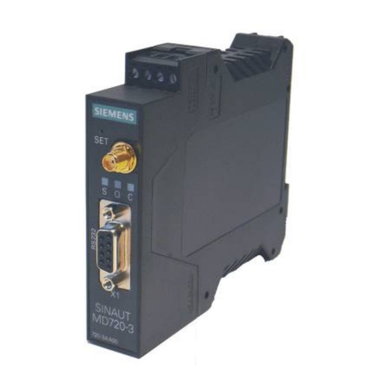
The antenna connector – SMA socket - is situated on the upper part of the front. Impedance: approx. 50 Ohm Caution Please use only antennas of the SINAUT MD720-3 accessory program. Other antennas may disturb the product characteristics and may even cause defects. SINAUT MD720-3... - Page 20 The devices switch on as soon as the operating voltage is supplied. Functions of the LEDs The SINAUT MD720-3 has three LEDs, which are used to indicate the device status. The function of the LEDs is different in terminal and OPC Mode. You will find the explanation of the function ●...
- Page 21 Load factory settings than 4 seconds (Connect) begins to light Top-hat rail mounting The SINAUT MD720-3 is suitable for top-hat rail mounting on DIN EN 50022 rails. A corresponding bracket can be found at the rear of the device. SINAUT MD720-3 C79000-G8976-C211...
- Page 22 Connecting the device and switching on the device SINAUT MD720-3 C79000-G8976-C211...
-
Page 23: Sinaut Md720-3 In Terminal Mode
The SINAUT MD720-3 is delivered by the factory with activated Terminal Mode. Switching from OPC Mode into the Terminal Mode If it is necessary to switch a manually the SINAUT MD720-3 from OPC Mode into the Terminal Mode, you will find the instructions for this in the chapter Switching between Terminal mode and OPC Mode. -
Page 24: Operating Requirements In Terminal Mode: Gprs Subscriber Contract
SINAUT MD720-3 in Terminal Mode Operating requirements in Terminal Mode: GPRS subscriber contract To use the SINAUT MD720-3 in Terminal Mode it is required: • SIM card of a GSM network operator including CSD data service 9600 Bit/s and an extra telephone number for data calls, •... -
Page 25: Terminal Mode Operation
To operate the device the PIN (PIN = Personnel Identification Number) of the inserted SIM card must be known. In the Terminal Mode the PIN is not stored in the SINAUT MD720-3. The PIN must be set again every time the device is turned- ●... -
Page 26: Entering At Commands
Duplex: Full PIN in Terminal-Mode Enter the PIN If the LED S blinks slowly (1 time each second), the SINAUT MD720-3 waits for a PIN entry. In Terminal-Mode the PIN need to be entered using the AT command AT+CPIN. Example: Command: at+cpin="0000“... - Page 27 SIM card is PUK-blocked, please enter the PUK and then a PIN. You can use a common mobile phone to do this. Before you enter again the SIM card into the SINAUT MD720-3, please investigate why the SIM card has been PUK-blocked: Which PIN have you entered or which...
-
Page 28: Use At Commands
SINAUT MD720-3 in Terminal Mode Use AT commands Syntax The AT command language is a standard for controlling modems. It is line- orientated. Each command line begins with AT (for ATtention), followed by the actual command, and ends with (Enter key). - Page 29 Enter the PIN Command: at+cpin="0000“ Response: OK Network-Status request Command: at+creg? Response: +CREG: 0,1 Firmware Version request Command: ati3 Response: SIE3171 SINAUT MD720-3 V.1.7.00 19.05.2006 CSD call outgoing: Command: atd0123456789 Response: CONNECT CSD call incoming: Response: RING Command: ata Response: CONNECT...
-
Page 30: Supported At Commands In Terminal Mode
SINAUT MD720-3 in Terminal Mode Supported AT commands in Terminal Mode All AT commands being not listed below will be answered with OK by the device, but the command will not be executed. Switch from data mode to command mode... - Page 31 SINAUT MD720-3 in Terminal Mode Mobile originated Call to dial a number Executive command Command: ATD[<n>] Response: The connection cannot be established: NO DIALTONE BUSY NO CARRIER NO ANSWER Data connection successfully connected: CONNECT[<text>] <n>: Parameter: String of dialing digits and optionally V.25ter modifiers (dialing digits): 0-9, * , #, +, A, B, C...
- Page 32 SINAUT MD720-3 in Terminal Mode Request identification information Read command Command: ATI[<value>] Response: <text> (depends on <value>) Parameter: <value>: none: Product name and Firmware Version Product name and Firmware Version Product name, Interface, Mode Product name and Firmware Version Notice: <text>...
- Page 33 SINAUT MD720-3 in Terminal Mode ATS0 Configures Automatic answering Executive command Command: ATS0=<n> Response: Parameter: <n>: automatic answering deactivated <Default> 1-255: number of rings before automatically answering Notice: GSM networks usually generate only 8-12 RING. If S0 is set to a higher value, calls are eventually not being answered.
- Page 34 SINAUT MD720-3 in Terminal Mode AT\Q Hardware Flow Control on/off Executive command Command: AT\Q<n> Response Parameter: <n>: Hardware Flow Control (RTS/CTS) off Hardware Flow Control (RTS/CTS) on Notice: Set CONNECT result code Format und Call monitoring Executive command Command: ATX[<value>]...
- Page 35 SINAUT MD720-3 in Terminal Mode AT&D Set circuit Data Terminal Ready (DTR) function mode Executive command Command: AT&D[<value>] Response: Parameter: <value>: Device ignores status on DTR. <Default> ON->OFF on DTR: Disconnect call, change to command mode. During state DTR = OFF is auto-answer off.
- Page 36 SINAUT MD720-3 in Terminal Mode AT+CCLK Clock Test Command: +CCLK=? Response: Read command Command: +CCLK? Response: +CCLK: <time> Executive command Command: AT+CCLK=<time> Response: +CME ERROR: <err> Parameter: <time>: String variable; the format is "yy/MM/dd,hh:mm:ss±zz", with Year Month Hour Minute Second Time zone, gives the difference between the local time and GMT, given in quarters of an hour;...
- Page 37 SINAUT MD720-3 in Terminal Mode AT+CRLP Radio link protocol Test Command: +CRLP=? Response: +CRLP: (list of supported <iws>s),(list of supported <mws>s), (list of supported <T1>s),(list of supported <N2>s),<ver1> ,(list of supported <T4>s) Read command Command: +CRLP? Response: +CRLP: <iws>,<mws>,<T1>,<N2>,<ver1>,<T4> Executive command Command: AT+CRLP=<iws>[,<mws>[,<T1>[,<N2>[,<ver>[,<T4>]]]]]...
- Page 38 SINAUT MD720-3 in Terminal Mode AT+CPIN Enter PIN Test Command: AT+CPIN=? Response: Read command Command: AT+CPIN? Response: +CPIN: <code> Executive command Command: AT+CPIN=<pin> [,<newpin>] Response: Parameter: <code>: Values reserved by this device: READY Device is not pending for any password...
- Page 39 SINAUT MD720-3 in Terminal Mode AT+CSQ Check Signal Quality Test Command: AT+CSQ=? Response: +CSQ: (list of supported <rssi>s),(list of supported <ber>s) Response: Command: AT+CSQ Response: +CSQ: <rssi>,<ber> Parameter: <rssi>: -113 dBm or less -111 dBm 2...30 -109... -53 dBm -51 dBm or greater not known or not detectable <ber>:...
- Page 40 SINAUT MD720-3 in Terminal Mode AT+CGDCONT Define PDP context Test Command: AT+CGDCONT=? Response: +CGDCONT: (range of supported <cid>s), <PDP_type>,,,(list of supported <d_comp>s), (list of supported <h_comp>s)[,(list of supported <pd1>s)[,…[,(list of supported <pdN>s)]]][...]] [+CGDCONT: (range of supported <cid>s), <PDP_type>,,,(list of supported <d_comp>s), (list of supported <h_comp>s)[,(list of supported <pd1>s)[,…[,(list of supported...
- Page 41 SINAUT MD720-3 in Terminal Mode The execute command specifies PDP context parameter values for a PDP context Notice: identified by the (local) context identification parameter, <cid>. The number of PDP contexts that may be in a defined state at the same time is given by the range returned by the test command.
- Page 42 SINAUT MD720-3 in Terminal Mode AT+CPAS Phone activity status Test Command: AT+CPAS=? Response: +CPAS: (list of supported <pas>s) Read command Command: AT+CPAS Response: +CPAS: <pas> Parameter: <pas>: ready (device allows commands from application) unavailable (device does not allow commands from application)
- Page 43 SINAUT MD720-3 in Terminal Mode AT+CPMS Preferred Message Storage Test Command: AT+CPMS=? +CPMS: (list of supported <mem1>s),(list of supported <mem2>s),(list of supported Response: <mem3>s), Read command Command: AT+CPMS? +CPMS: <mem1>,<used1>,<total1>,<mem2>,<used2>,<total2>,<mem3>, Response: <used3>,<total3> Executive command Command: AT+CPMS= <mem1>,<mem2>,<mem3> Response: +CPMS: <used1>,<total1>,<used2>,<total2>,<used3>,<total3>...
- Page 44 SINAUT MD720-3 in Terminal Mode <mem3>. AT+CNUM Subscriber number Test Command: AT+CNUM=? Response: Executive command AT+CNUM Command: Response: +CNUM: [<alpha1>],<number1>,<type1>[,<speed>,<service>[,<itc>]] [<CR><LF>+CNUM: [<alpha2>],<number2>,<type2>[,<speed>,<service> [,<itc>]] [...]] Parameter: <alpha>: optional alphanumeric string associated with <number>; used character set should be the one selected with command Select TE Character Set +CSCS <number>:...
- Page 45 SINAUT MD720-3 in Terminal Mode SINAUT MD720-3 C79000-G8976-C211...
- Page 46 SINAUT MD720-3 in Terminal Mode AT+CBST Select bearer service type Read command Command: AT+CBST=? Response: +CBST: (list of supported <speed>s),(list of supported <name>s),(list of sup- ported <ce>s) Executive command Command: AT+CBST=[<speed> [,<name>[,<ce>]]] Response: Parameter: <speed>: 2400 bps (V.22bis) 4800 bps (V.32) 9600 bps (V.32)
- Page 47 SINAUT MD720-3 in Terminal Mode AT+CMGF Select SMS message format Test Command: AT+CMGF=? Response: +CMGF: (list of supported <mode>s) Read command Command: AT+CMGF? Response: +CMGF: <mode> Executive command Command: AT+CMGF=[<mode>] Response: Parameter: <mode>: PDU mode Text mode Notice: AT+ CMGL...
- Page 48 SINAUT MD720-3 in Terminal Mode Parameter: <index> integer type; value in the range of location numbers supported by the associated memory <stat> integer type (default 0: "REC UNREAD"); indicates the status of message in memory; defined values: 0 "REC UNREAD" received unread message (i.e. new message) 1 "REC READ"...
- Page 49 SINAUT MD720-3 in Terminal Mode AT+CMGR Read SMS message Test Command: AT+CMGR=? Response: Executive command Command: AT+CMGR=<index> Response: In text mode (+CMGF=1) If command is executed successfully and SMS-DELIVER: +CMGR: <stat>,<oa>,<scts>,<length> <CR><LF><data><CR><LF> If command is executed successfully and SMS-SUBMIT: +CMGR: <stat>,<da>,<length>...
- Page 50 SINAUT MD720-3 in Terminal Mode AT+CMGS Sending SMS Test Command: AT+CMGS=? Response: Executive command In text modus (+CMGF=1): Command: +CMGS=<da>,<toda><CR> > text is entered<ctrl-Z/ESC> In PDU mode (+CMGF=0): AT+CMGS=<length><CR> enter PDU <ctrl-Z/ESC> In text mode (+CMGF=1) and successful sending: Response:...
- Page 51 SINAUT MD720-3 in Terminal Mode AT+CNMI New SMS message indication Test Command: AT+CNMI=? Response: +CNMI: (list of supported <mode>s), (list of supported <mt>s), (list of supported <bm>s), (list of supported <ds>s), (list of supported <bfr>s) 2. Read command Command: AT+CNMI? Response: +CNMI: <mode>,<mt>,<bm>,<ds>,<bfr>,OK...
- Page 52 SINAUT MD720-3 in Terminal Mode AT+CREG Network registration Test AT+CREG=? Command: +CREG: (list of supported <n>s) Response: Read command AT+CREG? Command: +CREG: <n>,<stat>[,<lac>,<ci>] Response: Executive command Command: AT+CREG=<n>,<stat> Response: Parameter: <n>: disable network registration unsolicited result code enable network registration unsolicited result code +CREG: <stat>...
- Page 53 SINAUT MD720-3 in Terminal Mode AT+CSCA SMS service center address Test Command: AT+CSCA=? Response: Read command Command: AT+CSCA? Response: +CSCA: <sca>,<tosca> Executive command Command: AT+CSCA=<sca>[,<tosca>] Response: Parameter: <sca> “Phone number SMS-ServiceCenters” <tosca> 129, 145 Notice: Executive command updates the SMSC address, through which mobile originated SMS are transmitted.
- Page 54 SINAUT MD720-3 in Terminal Mode AT+CSMP Set SMS text mode parameters Test AT+CSMP=? Command: Response: +CSMP: (list of <fo>),(list of <vp>),(list of <pid>),(list of <dcs>) Read command Command: AT+CSMP? Response: +CSMP: <fo>,<vp>,<pid>,<dcs> Executive command Command: AT+CSMP=[<fo>[,<vp>[,<pid>[,<dcs>]]]] Response: Parameter: <fo> <vp>...
- Page 55 SINAUT MD720-3 in Terminal Mode AT+CRC Set Cellular Result Codes for incoming call indication Test Command: AT+CRC=? Response: +CRC: (list of supported <mode>) Read command Command: AT+CRC? Response: +CRC:<mode> Executive command Command: AT+CRC=[<mode>] Response: <mode>: Parameter: disable extended format enable extended format...
- Page 56 The command has no impact to GPRS connections or the sending of SMS. In mobile operation <stat> must be set to zero. Composed AT commands The initialization strings below are accepted by the SINAUT MD720-3. The reaction to the separate commands correspondingly. TIM device ATE0S0=1&D2+CBST=71,0,1;+CRC=1;&W+IPR=19200...
-
Page 57: Sinaut Md720-3 In Opc Mode
SINAUT MD720-3 in OPC Mode GPRS modem In the OPC Mode the SINAUT MD720-3 is configured by program building blocks of the connected S7-200 PLC. The SINAUT MD720-3 establishes autonomous the radio data connection via GPRS between the connected S7-200 device and the OPC server SINAUT MICRO SC. -
Page 58: Opc Mode Activation
● Terminal mode ● OPC Mode. The SINAUT MD720-3 will be delivered by the factory with activated Terminal Mode. Automatic activation by the PLC Operating the SINAUT MD720-3 in OPC Mode combined with S7-200 devices, the OPC Mode will be activated by the program building blocks automatically during the initialization. -
Page 59: Functions Of The Leds In Opc Mode
SINAUT MD720-3 in OPC Mode Functions of the LEDs in OPC Mode The device is equipped with 3 LEDs which indicate the status: S (Status) Q (Quality) C (Connect) Status Meaning S, Q, C Fast lighting in sequence Boot procedure... -
Page 60: Pin In Opc-Mode
SINAUT MD720-3 in OPC Mode PIN in OPC-Mode Enter the PIN If the LED “S” blinks slowly (1 time per second), the SINAUT MD720-3 waits for a PIN entry. In OPC-Mode the PIN is sent by the connected PLC to the SINAUT MD720-3. - Page 61 SINAUT MD720-3 in OPC Mode 1. Please make sure, that the correct PIN is entered into the PLC program module. 2. Push the SET button until the factory default settings has been loaded (Attention, all settings will be reset) Enter the following AT commands:...
-
Page 62: Log In To Sinaut Micro Sc
After the SINAUT MG720-3 is switched on and configured by the control or after a connection is broken off the SINAUT MD720-3 starts at once to connect itself with the OPC Server SIANAUT MICRO SC, if the SINAUT MD720-3 is in OPC mode. -
Page 63: Service Functions
Switching between Terminal mode and OPC Mode The SINAUT MD720-3 is delivered by the factory with activated Terminal Mode. Operated in combination with a S7-200 the OPC Mode of the SINAUT MD720-3 will be activated by program building blocks of the connected S7-200 PLC during the initialization. - Page 64 Activates the AT configuration AT^PARSET=”TERMINAL”,”MODE”,”SUPERVISED” <CR> Selects the Terminal Mode, or AT^PARSET=”TERMINAL”,”MODE”,” ”<CR> DISABLE Selects the OPC Mode. AT^PAREND<CR> Deactivates the AT configuration and forces a restart of the SINAUT MD720-3. The device restarts in the selected new operating mode. SINAUT MD720-3 C79000-G8976-C211...
-
Page 65: Getting The Current Settings And Values
HyperTerminal. Select the used COM interface of the PC and configure the character format and the baudrate to the same settings as the X1 interface of the SINAUT MD720-3. By factory default the SINAUT MD720-3 has the following settings: Baudrate 9600 Bit/s (in OPC Mode) or... -
Page 66: Service Mode To Download A New Firmware
SINAUT MD720-3. You can find the latest firmware in the internet on the pages of des Siemens Service & Support (see Foreword). - Page 67 15. In the Properties window of this modem select the Modem tab. Set the speed to 57600. Close the window. Installation of a Network Connection The communication with the SINAUT MD720-3 in service mode is made via a network connection. 1. Open the Control Panel in the Start menu.
- Page 68 You will be asked for a User name (default: service) and a password (default: service). Enter both and observe capital or small characters. If the connection is established successfully the message „230 User logged in“ appears and the prompt changes to Ftp>. SINAUT MD720-3 C79000-G8976-C211...
- Page 69 Press Enter. After the firmware file and the !cmdfile file are successfully uploaded the SINAUT MD720-3 will start to install the new firmware. This process can last up to 10 minutes. After this the SINAUT MD720-3 restarts. Then the SINAUT MD720-3 is ready again.
-
Page 70: Load Factory Defaults
Service functions Load factory defaults By pushing the SET button for more than 4 seconds till the LED “C” begins to light up, the configuration of the SINAUT MD720-3 will be reset to factory default settings. SINAUT MD720-3 C79000-G8976-C211... -
Page 71: Technical Data
Established GPRS at 12V Burst connection with 1400 data exchange 1200 1000 [ms] [mA] at 24V Burst 1400 1200 1000 [ms] 430mA at 12V (I 1,3A), Burst 165mA at 24V (I 0,8A), Burst 4,62ms Burst repetition rate SINAUT MD720-3 C79000-G8976-C211... - Page 72 CLI, Zone 2 IIC, T4 Ta=-20°C-60°C E301826 Interface X1 Signals SUB-D9 socket, Pin assignment (Signal direction DTE) RS232 Pin1 DCD Output Pin2 RXD Output Pin3 Input Pin4 Input Pin5 GND Signal ground Pin6 DSR Output Pin7 Input Pin8 Output Pin9 Output SINAUT MD720-3 C79000-G8976-C211...
- Page 73 Technical Data Modem cable for Service Interface to Modem to PC DSUB DSUB 9-pin 9-pin connector plug The line RI is an option. SINAUT MD720-3 C79000-G8976-C211...
- Page 74 Technical Data SINAUT MD720-3 C79000-G8976-C211...
-
Page 75: Glossary
PPP. COM-Port The term "COM port" (communications port) is used to describe a serial interface (RS232) on a Windows PC. Application programs use COM ports for data transmission to various devices such as modems, PCs, terminals etc. SINAUT MD720-3 C79000-G8976-C211... - Page 76 Technical Data SINAUT MD720-3 C79000-G8976-C211...
Need help?
Do you have a question about the SINAUT MD720-3 and is the answer not in the manual?
Questions and answers