Siemens TC35 Terminal User Manual
Compact gsm modem
Hide thumbs
Also See for TC35 Terminal:
- User manual (39 pages) ,
- Application (9 pages) ,
- At command reference (204 pages)

Related Manuals for Siemens TC35 Terminal


Summary of Contents for Siemens TC35 Terminal
- Page 1 TC35 Terminal User Guide Wireless www.siemens.com/wm www.siemens.com/wm be inspired Modules...
-
Page 3: Safety Information
Safety information Radio devices have limitations in the vicinity of electronic devices: • Switch the TC35 Terminal off when you are in a hospital or near medical devices like pacemakers or hearing aids. The Terminal may interfere with the operation of these devices. -
Page 4: Table Of Contents
Contents Safety information ........ 1 Contents ..........2 Overview ..........4 Front view .......... 4 Rear view ........... 4 Product description....... 5 Highlights ........... 6 Applications ........6 Features..........7 Product data ........7 Certification ........7 Audio..........7 SMS ........... 7 Data ........... - Page 5 Contents Operating states / LED ......29 POWER DOWN ....... 30 Network search ....... 31 Standby ..........31 Talk ..........31 AT command control ......32 SW update ........... 33 Compatibility ........34 Compatibility withthe predecessor, the M20Terminal ......34 Certification / maintenance ....
-
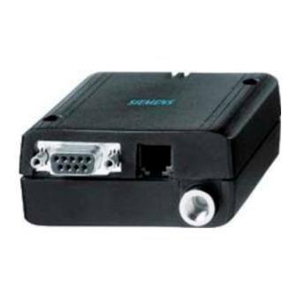
Page 6: Overview
Overview Front view Plug-in power RS232 interface Antenna connector (9-pin D-Sub) Rear view LED display Mini-SIM Handset connector card holder... -
Page 7: Product Description
Product description The TC35 Terminal is a compact GSM modem for the transfer of data, voice, SMSand faxes in GSM networks. Industrial standard interfaces and an integrated SIMcard reader mean it can be used rapidly, easily and universally as a dual band GSM Terminal. -
Page 8: Highlights
Product description Highlights • Dual-band EGSM900 / GSM1800 • Data, voice, SMS and fax • R&TTE approval, GCF approval • Easy to integrate • Industrial interfaces • LED display • Wide input voltage range • Highly compact, light and powerful Applications •... -
Page 9: Features
Features Product data • Dual-band EGSM900 and GSM1800 • Certified in accordance with GSM phase2/2+ • Output performance: – Class 4 (2 W) for EGSM900 – Class 1 (1 W) for GSM1800 • Control via AT commands • Input voltage range +8V ... +30V •... -
Page 10: Supplementary Services
Features Supplementary • Phone book services • Multiparty • DTMF (Dual Tone Multi Frequency) External interfaces • Connector for plug-in power supply unit • Handset audio interface • Mini-SIM card holder • Antenna connector FME (male) • RS232 interface (V.24/V.28 on the Sub-D socket) Accessories Antennae, SIM cards, power supply units,... -
Page 11: Installation
SIEMENS TC35 Terminal. Attaching The TC35 Terminal can be attached with two screws. Use screws approx.50 mm long theTerminal and Ø 3mm. The TC35 Terminal can be attached to a top-hat rail using an additional... - Page 12 Installation Mounting kit for top-hat rail installation The TC35 Terminal can be attached to a 35mm top-hat rail using this mounting kit. There are two screws that are used tofix the top-hat rail adapter to the TC35 Terminal. The TC35 Terminal can be inserted onto the...
-
Page 13: Interface Description
• Antenna connector FME (male) • RS232 interface (V.24/V.28 on the D-Sub socket) Plug-in power The TC35 Terminal receives its power supply in a wide voltage range (+8 V ... +30 V) via supply unit the power supply connectors. Two additional control lines are used for switching the Terminal on/off (resetting). - Page 14 Interface description Purpose of the connectors/connections Signal PIN I/O Description Parameters name Positive supply voltage +8V...+30V connection max. 33V for 1min Free PD_IN Reset input > + 5 V high active (>3.5s) < + 2 V IGT_IN Ignition input > +5V high active (>200ms) <...
- Page 15 Fuses A permanently installed, non-replaceable fuse in the TC35 Terminal ensures electrical safety in the event of faults. Connect a fast 1.25A fuse to the supply line of the positive supply voltage for general protection of the Terminal, see "Safety and installation...
- Page 16 Interface description Interference immunity • The cable length must not exceed 3m • Current carrying capacity <1.5A (Western modular jack) • Nominal signal range: 0...+30V • Max. load current 1.5A • Electrical fast transient burst requirements in accordance with ETS 300-342-1 •...
-
Page 17: Handset Connector
Threeaudio modes are prepared in the GSM module for this purpose. Mode 1 (default): The "Handset for Cellular Engine Siemens Terminal M20T, MC35T, TC35T, DSB35" can be connected to the TC35 Terminal (approved configuration and recommended handset). Mode 4: Any handset can be connected to the TC35Terminal. - Page 18 Interface description Handset connector 1 MICN 2 EPN 3 EPP 4 MICP Purpose of the connectors/connections Signal PIN I/O Description Parameters name MICN DC:O Microphone input DC (no load): AC:I minus = 6 . 0 V ± 1 0 % (MICP) MICP DC:O...
- Page 19 ETS 300-342-1 • Immunity RF common mode 0.15–80MHz in accordance with ETS300-342-1 Connectible handset Item Order no. Supplier Votronic handset HH-SI-30.3/ Votronic GmbH Handset for V1.1/0 Saarbrücker Str. 8 the TC35 Terminal D-86386 St. Ingbert Tel.: +4968949255-44 Fax: +4968949255-88...
- Page 20 GSM11.12 phase2 to operate the Terminal. The SIM card (3V type) must be inserted in the card holder to put the TC35 Terminal into operation. 1. Make sure that there is no voltage applied to the TC35 Terminal.
- Page 21 Interface description 3.Insert the SIM card in the SIM card holder and push it back into the housing.
- Page 22 Interface description Purpose of the connectors/connections Signal PIN I/O Description of the Parameters name GSM module connectors = 1 0 0 k Ω to GND CCIN Input for detection of the SIM card; = 0 . 4 V iLmax high active @ I = 0 .1mA = 1.95V iHmin...
-
Page 23: Antenna Connector
Interface description The Bootbox BB35 enables software to be updated via the SIM interface. The Bootbox is connected instead of a SIM card (see "Bootbox BB35" on page33). Interference immunity Electrostatic discharge requirements in accordance with ETS 300-342-1 Antenna connector A dual band antenna (GSM 900/1800) can beconnected to the RF interface. - Page 24 Interface description Transmission type and method • Digitally modulated RF burst signal • GMSK in accordance with GSM05.04 • Half duplex • Bidirectional Interference immunity • Electrostatic discharge requirements in accordance with ETS 300-342-1 • Electrical fast transient burst requirements (cable is >3m) •...
-
Page 25: Rs232 Interface
The RS232 interface is the interface for the application software and the connection to the PC. The customer application communicates with the TC35 Terminal or the TC35 GSM engine by means of ATcellular commands. The RS232 interface is implemented as a 9-pin D-Sub socket with a screw fitting. - Page 26 Interface description Purpose of the connectors/connections Signal PIN I/O Description Parameters name The functions active high >5V correspond to those low <–5V of a serial interface logical 1=low <–5V on the basis of a logical 0=high >+5V V.24 protocol. active high >2.4V low <1.8V active high >2.4V low <1.8V...
- Page 27 Interface description Interference immunity • The connecting cable must not exceed 1.8m in length. • Nominal signal range: ±15V • Max. load current 1A • Electrical fast transient burst requirements not specified • Surge immunity requirements not specified • Electrostatic discharge requirements in accordance with ETS 300-342-1 •...
-
Page 28: Startup
The SIM card must be inserted in a deenergized state. The TC35 Terminal is ready for operation when supply voltage is applied and the ignition line is activated. If the recommended plug-in power supply unit is... -
Page 29: Switching Off / Resetting The Terminal
VBAT=operating voltage for the GSM module VDD=supply voltage from the module Activation of the RS232 control line DTR The TC35 Terminal can be switched on in the same way as via IGT_IN by activating the RS232 control line DTR (high signal). Note... - Page 30 To do this, the PD_IN Terminal reset line is active (high) for at least 3.5s. This results in immediate, "hard" disconnection, with the TC35 Terminal unable to sign off correctly from the base station in the STANDBY and TALK operating states .
-
Page 31: Operating States / Led
Operating states / LED The LEDs display the following operating states of the Terminal: Operating state After connecting the plug- On for 2 s in power supply unit POWER DOWN – Network search or Flashes rapidly – no SIM card is inserted –... -
Page 32: Power Down
GSM network is available. POWER DOWN Once the operating voltage is applied (+ and GND), the TC35 Terminal is in the POWER DOWN state. The operating voltage for the GSM module is disconnected (the switching regulator is off). -
Page 33: Network Search
• From the TALK or STANDBY state: when the network is lost (out of range) Standby In the STANDBY state, the TC35 Terminal is ready to send and receive and registered in the network. Paging is performed with the GSM network in order to obtain... -
Page 34: At Command Control
AT command control The TC35 Terminal is controlled and programmed by means of AT commands. The AT command structure corresponds to the TC35 module used. The AT commands can be obtained from the ICM WM home page: www.siemens.com/wm. -
Page 35: Sw Update
SW update A SW update for the TC35 Terminal takes place via the RS232 interface or the SIM interface. These interfaces must be designed in such a way that the upgrading ofthe TC35 Terminal is integrated in the application. The software can be obtained from the ICM WM home page. -
Page 36: Compatibility
Compatibility Compatibility The direct predecessor of the TC35 Terminal is the M20 Terminal. withthe predecessor, the The antenna connector is not compatible. M20Terminal The modified version (passive version) of the Votronic handset must be operated at the audio interface in accordance with HH-SI-30.3/V1.1/0. -
Page 37: Certification / Maintenance
Certification / maintenance Certification The TC35 with its IMEI number is approved for operation in GSM networks and complies with the following EU directives: • Directive 89/336/EEC on electromagnetic compatibility • Directive 98/13/EC, CTR 19 and CTR 20, on telecommunications Terminal equipment •... -
Page 38: Index
Index Accessories 8 Network search 31 Antenna connector 4, 11, 21 AT command control 32 Operating state 29 Audio 7 Overview 4 Overvoltage 13 Bootbox 33 Package contents / scope of Certification 7, 35 delivery 9 Compatibility 34 Plug-in power supply unit 4, 11 Polarity reversal 13 Power down 30 Data 7... - Page 39 Issued by Siemens AG ICM Wireless Modules Haidenau Platz 1, D-81667 Munich Germany www.siemens.com/wm Subject to changes in technology and availability. Order no.: A31008-H8600-A1-1-7619 Printed in Germany Wireless be inspired Modules...
Need help?
Do you have a question about the TC35 Terminal and is the answer not in the manual?
Questions and answers