
Subscribe to Our Youtube Channel
Related Manuals for Siemens tc35it


Summary of Contents for Siemens tc35it
- Page 1 Siemens TC35iT Installation & Programming Manual Skye Instruments Ltd., 21 Ddole Enterprise Park, Llandrindod Wells, Powys LD1 6DF UK. Tel: +44 (0) 1597 824811 email: skyemail@skyeinstruments.com www.skyeinstruments.com...
-
Page 2: Table Of Contents
SING A STANDARD TELEPHONE LINE AT THE 3.2 U TC35 .................7 SING A SECOND CELLULAR MODEM AT THE 3.2.1 Programming the TC35iT for the Datalogger site.................7 3.2.2 Programming the TC35iT for the PC....................8 3.3 N TC35 ......................9 OTES ON MODEM PROGRAMMING 4. -
Page 3: Tc35It Installation & Programming Manual
GSM network. The Siemens TC35iT modem is dual band for use with a 900 or 1800 MHz GSM cellular telephone system only. An airtime contract and SIM card must be obtained from the mobile phone network provider. -
Page 4: Installing The Siemens Tc35It Modem
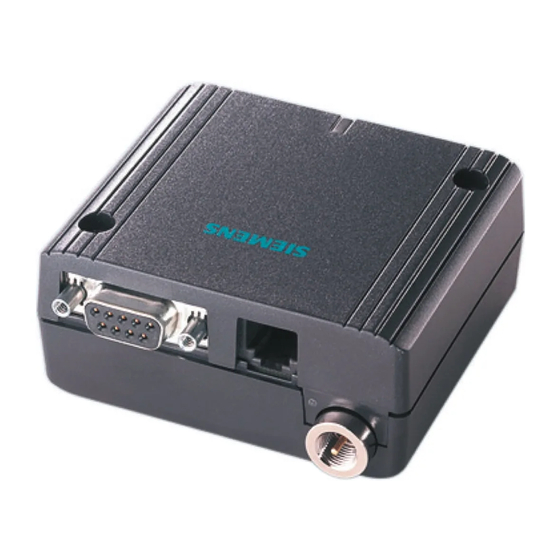
Unit. See Figure 1. There are 2 sockets on the TC35iT. The Skye GSM Modem Unit has a grey 9 pin D connector and a small clear connector with 6 gold contacts which match these sockets. Push the clear connector into its socket, connect the grey D connector and screw up to secure. -
Page 5: Programming The Tc35It Modem
TC35iT UNIT BEFORE OTHER CONNECTIONS ARE MADE, THE MODEM CAN BE PERMANENTLY DAMAGED. 1. Disconnect the grey 9 pin D connector from the GSM Modem Unit to the TC35iT. Replace this with the male end of the Skye 'TC35iT programmer' cable. Connect the female end to a serial port of a PC. - Page 6 To check the TC35iT is correctly set up, make a call from it through the PC (if an airtime contract barring outward calls is in place, this may not be possible). To do this type atdt then the telephone number, then press return.
-
Page 7: Using A Second Tc35It Cellular Modem At The Pc End
3.2.1 Programming the TC35iT for the Datalogger site 1. Disconnect the grey 9 pin D connector from the GSM Modem Unit to the TC35iT. Replace this with the male end of the Skye 'TC35iT programmer' cable. Connect the female end to a serial port of a PC. -
Page 8: Programming The Tc35It For The Pc
To check the TC35iT is correctly set up, make a call from it through the PC (if an airtime contract barring outward calls is in place, this may not be possible). To do this type atdt then the telephone number, then press return. -
Page 9: Notes On Tc35It Modem Programming
To check the TC35iT is correctly set up, make a call from it through the PC (if an airtime contract barring outward calls is in place, this may not be possible). To do this type atdt then the telephone number, then press return. - Page 10 TC35iT Installation & Programming Manual at+cbst=0,0,1 autobauding (for connecting an analogue modem or a TC35iT at PC end to the TC35iT modem at the MiniMet end) at+cbst=7,0,1 instructs a V32 analogue modem connection @ 9600 baud (for connecting an analogue modem at PC end to the TC35iT modem at the MiniMet end)
-
Page 11: Modes Of Operation
Please contact Skye for details. When the red LED ‘modem active’ is lit, then power is being applied to the TC35iT modem and the green LED on the modem itself should flash slowly, about 1 flash per second. When a call is being connected to the modem, this green LED will flash much faster. -
Page 12: Inside The Gsm Modem Unit
TC35iT Installation & Programming Manual FIGURE 1 Inside the GSM Modem Unit... -
Page 13: Cable Entries On Base Of Gsm Modem Unit
TC35iT Installation & Programming Manual FIGURE 2 Cable Entries on base of GSM Modem Unit Port 1 – aerial cable Port 2 – RS232 cable to DataHog Port 3 – solar panel cable (where not used, this will be fitted with a blanking plug) Port 4 –... -
Page 14: Modem Power Control
TC35iT Installation & Programming Manual FIGURE 3 Modem Power Control The GSM Housing box encloses the GSM modem itself, plus electronics for controlling the modem, the power supply and solar power regulator. There are ‘power on’ options for timed operation, permanently on or permanently off. These 3 options are controlled by a set of jumper pins on the PCB as shown below. -
Page 15: Appendix 1 - Using Windows Hyperterminal
Stop bits Flow Control No handshake Click OK. 7. Click on FILE and EXIT. Click YES and YES again to save the settings you have chosen. Wait a few moments and you should see your chosen icon appear called TC35iT. -
Page 16: Appendix 2 - Wiring Details For Modem Programming Cable
TC35iT Installation & Programming Manual APPENDIX 2 - Wiring Details for Modem Programming Cable 2 metres of 2 core screened cable Attach grey wires to cable screen either end MODEM END PC END Male 9 pin D connector Female 9 pin D connector...
Need help?
Do you have a question about the tc35it and is the answer not in the manual?
Questions and answers