
Related Manuals for ALTAI A2


Summary of Contents for ALTAI A2
-
Page 1: Installation Guide
ALTAI A2 WIFI ACCESS POINT/BRIDGE INSTALLATION GUIDE Version 1.0 () Date: September, 2013 Altai Technologies Ltd. All rights reserved... - Page 2 Altai A2 WiFI Access Point/Bridge Installation Guide TPS13-002_rev1.0 Copyright © 2007 Altai Technologies Limited ALL RIGHTS RESERVED. Altai Technologies Limited Unit 209, 2/F, East Wing, Building 17, Hong Kong Science Park, Shatin, New Territories, Hong Kong Telephone: +852 3758 6000...
- Page 3 This document is provided for information purposes only. Altai Technologies reserves the right to change, modify, transfer, or otherwise revise this publication without notice.
-
Page 4: Table Of Contents
Grounding A2 WiFi Access Point/Bridge ................... 20 2.9. Surge Protection ..........................20 2.10. ESD Protection ..........................21 2.11. Resetting A2 WiFi Access Point/Bridge to factory default settings ........21 2.12. Reviewing Installation Procedures ..................... 22 Typical Site Setups ..........................22 Altai Technologies Ltd. All rights reserved... -
Page 5: Introduction
Altai A2 WiFI Access Point/Bridge Installation Guide TPS13-002_rev1.0 1. Introduction This document is written to provide the information needed to mount A2 WiFi Access Point/Bridge and A2 antennas on site location. This document is applicable for hardware platform A2 and the following models. - Page 6 Altai A2 WiFI Access Point/Bridge Installation Guide TPS13-002_rev1.0 Figure 2-1 typical A2 Package Product: A2 WiFi Access Point/Bridge × 1 Accessories: Mounting Kit × 1 (Set) One PoE Power Injector ×1 Waterproof Plug × 1 (Set) ...
-
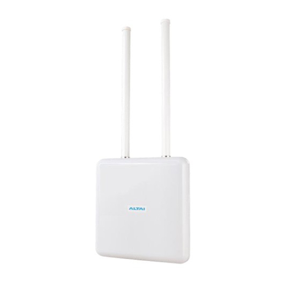
Page 7: Introducing A2 Wifi Access Point/Bridge
Altai A2 WiFI Access Point/Bridge Installation Guide TPS13-002_rev1.0 Figure 2-2 Mounting Kit detail 2.2. Introducing A2 WiFi Access Point/Bridge Figure 2-3 A2 Back View Note: Warranty will be voided if warranty labels are broken Highly recommended to configure the bridge setting (e.g. the Frequency channel, remote bridge MAC, security type) before site installation. -
Page 8: Installing A2 Wifi Access Point/Bridge
3) Waterproof Seal 2.4. 2.4 Mounting A2 WiFi Access Point/Bridge 1. Install the mounting bracket at the back of A2 WiFi Access Point/Bridge Figure 2-4 A2 main unit on the mounting bracket 2. Fix A2 WiFi Access Point/Bridge relevant the real situation (a) Fix the mounting bracket on the pole using hose clamps. - Page 9 Altai A2 WiFI Access Point/Bridge Installation Guide TPS13-002_rev1.0 Figure 2-5 Mount the bracket on the pole (b) Fasten A2 main unit on the wall with the mounting bracket and bolt Figure 2-6 Mount the bracket on the wall Altai Technologies Ltd. All rights reserved...
- Page 10 Altai A2 WiFI Access Point/Bridge Installation Guide TPS13-002_rev1.0 (A2 AP Mode) Install a pair of omni-directional antennas to A2 WiFi Access Point/Bridge RF ports, and properly seal the connections with waterproof sealing tape. A typical waterproof sealing tape is shown in 错误!未找到引用...
-
Page 11: Connecting Ethernet Cable To A2 Waterproofing Cable Protector
1. Depends on deployment site requirements, CAT5e (or above) Ethernet cable with appropriate length (maximum 100m) should be prepared before A2 installation. Please check the waterproof plug set as shown in the figure below. Figure 2-9 Waterproof Plug Set... - Page 12 Altai A2 WiFI Access Point/Bridge Installation Guide TPS13-002_rev1.0 2. Mount the housing and screw nut as picture below Figure 2-10 Mount the housing and screw nut 3. Put the seals in the housing. Figure 2-11 Put the seals in the housing...
- Page 13 Altai A2 WiFI Access Point/Bridge Installation Guide TPS13-002_rev1.0 4. Put the seals in the housing in to the Ethernet connector parts as the sequence denote in the pictures. Figure 2-12 Insert the cable Figure 2-13 Connect together 5. Use wire stripping tool to remove Ethernet cable jacket. Pull the sticker off from the gasket of the Ethernet plug and paste it to housing through the Ethernet cable.
- Page 14 Altai A2 WiFI Access Point/Bridge Installation Guide TPS13-002_rev1.0 Figure 2-14 Pull the sticker off Figure 2-15 Strip the jacket of cable and paste the gasket 6. At the end of cable, RJ-45 modular pins should be numbered 1 through 8 as...
- Page 15 Altai A2 WiFI Access Point/Bridge Installation Guide TPS13-002_rev1.0 The assignments of wire pairs to plug and jack pins are as follow: Pair wire Color white/orange stripe orange solid white/green stripe blue solid white/blue stripe green solid white/brown stripe brown solid Table 2-2 Cable wire pairs Caution: Recommended proper sealing to outdoor connector.
- Page 16 Altai A2 WiFI Access Point/Bridge Installation Guide TPS13-002_rev1.0 Figure 2-17 Cable modular and connection to A2 Altai Technologies Ltd. All rights reserved...
- Page 17 3) Start wrapping a layer of butyl rubber tape from 1” (25mm) below the edge of the cable connector. Overlap the tape to half –width. Take extra care to make sure that the cable connector-A2 Ethernet port junction is tightly sealed. Press the tape edges together so that there are no gaps. Press the tape against the cable connector body and the Ethernet port.
-
Page 18: General Antenna And Safety Recommendations
Altai A2 WiFI Access Point/Bridge Installation Guide TPS13-002_rev1.0 Figure 2-19 Unused RF Ports Waterproof Protection For both unused RF ports, retain the RF caps on the ports. Start wrapping a layer of butyl rubber tape from the bottom of RF port. Overlap the tape to half –width. -
Page 19: 5Ghz Antenna Alignment Led
+16dBi patch antenna are approximately between 25 to 30 degrees. A2 can be configured to show the signal strength using two LED lights. When the signal is weak, the lower light will be off. When the signal strength exceeds the highest level configured in the web interface, the lower light will be solid on. -
Page 20: Grounding A2 Wifi Access Point/Bridge
TPS13-002_rev1.0 2.8. Grounding A2 WiFi Access Point/Bridge It is essential to properly ground all equipment to prevent the A2 from the electrical damage and possible electric hazer due to non-proper power grounding. Use a 10AWG grounding wire to connect to the ground connector of the A2 WiFi Access Point/Bridge by screw driver. -
Page 21: Esd Protection
Technicians should always wear proper ESD grounding straps connected to the ESD connector during equipment installation, maintenance and repairs. 2.11. Resetting A2 WiFi Access Point/Bridge to factory default settings Altai Technologies Ltd. All rights reserved... -
Page 22: Reviewing Installation Procedures
Altai A2 WiFI Access Point/Bridge Installation Guide TPS13-002_rev1.0 Press the reset button with a thin stick for 5~10 seconds to reset A2 to factory default settings. Caution: All settings will be restored to factory default after the reset procedure! 2.12. Reviewing Installation Procedures... - Page 23 Altai A2 WiFI Access Point/Bridge Installation Guide TPS13-002_rev1.0 Typical Indoor AP Setup Typical Outdoor Bridge Setup Figure 3-2 A2 outdoor setup back-view Figure 3-1 Indoor A2 Setup back-view Altai Technologies Ltd. All rights reserved...
Need help?
Do you have a question about the A2 and is the answer not in the manual?
Questions and answers