Table of Contents
Advertisement
Quick Links
SCAN THIS QR CODE
with your smartphone or
visit http://goo.gl/nvneR
to view maintenance
videos for L.B.White
heaters.*
*Requires an app like QR Droid for Android or
QR Reader for iPhone.
Owner's Manual and Instructions
Congratulations!
You have purchased the finest kerosene portable forced air construction
heater available.
manufacturer of heating products using state-of-the-art technology.
We, at L.B. White, thank you for your confidence in our products and welcome any
s
uggestions or comments you may have...call us, toll-free, at (800) 345-7200
or e-mail customerservice@lbwhite.com
ATTENTION ALL USERS
This heater has been tested and evaluated by C.S.A. International in accordance with
the requirements of Standard UL733 and ANSI A10.10-1998, CAN/CSA B140.0-03
and CSA B140.8 - 1967 and is listed and approved as a Kerosene forced-air
construction heater with application for the temporary heating of buildings under
construction, alteration, or repair. If you are considering using this product for any
application other than its intended use, then please contact the L.B. White Co., Inc.
Quality heaters you can count on.
411 Mason St., Onalaska, WI 54650 • (800) 345-7200 • (608)783-5691 • (608) 783-6115, fax • info@lbwhite.com
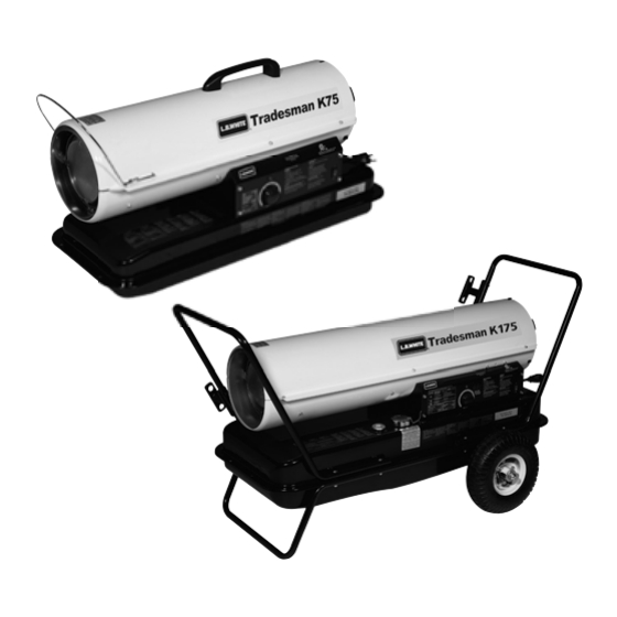
Tradesman Kerosene Heaters
MODELS
OUTPUT (BTUH)
CP045DK
45,000
CP075DK
75,000
CP125EK
125,000
CP175EK
175,000
CP210EK
210,000
Certification by:
C
US
150-28814
FUEL
1-K
Kerosene
Advertisement
Table of Contents

Related Manuals for L.B. White CP045DK


Summary of Contents for L.B. White CP045DK
- Page 1 QR Reader for iPhone. manufacturer of heating products using state-of-the-art technology. We, at L.B. White, thank you for your confidence in our products and welcome any uggestions or comments you may have...call us, toll-free, at (800) 345-7200 or e-mail customerservice@lbwhite.com ATTENTION ALL USERS This heater has been tested and evaluated by C.S.A.
- Page 2 Only properly-trained service people should repair or install this heater. Save this Owner’s Manual for future use and reference. Owner’s Manuals and replacement labels are available at no charge. See website, or for assistance, contact L.B. White at 800-345-7200. WARNING WARNING Fire and Explosion Hazard Fire and Explosion Hazard Not for home or recreational vehicle use.
-
Page 3: Table Of Contents
Parts Schematic (CP045DK & CP075DK) ........ -
Page 4: Heater Specifications
Heater Specifications Model SPECIFICATIONS CP045DK CP075DK Fuel Type 1-K, Kerosene Max Input (BTUH) 45,000 75,000 Pump Pressure (psig) Fuel Consumption per Hour (gal) Ball Bearing Motor Characteristics 1/8 HP, 3,300 RPM 1/8 HP, 3120 RPM Electrical Supply (Voltz/Hz/Phase) 120/60/1 CONTINUOUS... - Page 5 Heater Specifications Model SPECIFICATIONS CP125EK CP175EK CP210EK Fuel Type 1-K, Kerosene 125,000 175,000 210,000 Max Input (BTUH) Pump Pressure (PSIG) Fuel Consumption per Hour (gal) 1.32 Ball Bearing Motor Characteristics 1/5HP 3455 RPM 1/4HP 3430 RPM 1/3HP 3380 RPM Electrical Supply (Voltz/Hz/Phase) 120/60/1 CONT INUOUS Amp Draw...
-
Page 6: Safety Information
Safety Information HAZARD DEFINITIONS DANGER Indicates an imminently hazardous situation which, if not avoided WILL result in death or serious injury. WARNING Indicates a potentially hazardous situation which, if not avoided, COULD result in death or serious injury. CAUTION Indicates a potentially hazardous situation which, if not avoided, MAY result in minor or moderate injury. - Page 7 GENERAL SAFETY INFORMATION (cont.) CANADIAN RESIDENTS: Use of this heater shall be in WARNING accor dance with authorities having juris diction and Risk of CO Poisoning! CSA Standard B139. - Use this heater only in well ventilated areas. Provide proper ventilation. Proper ventilation air for NEW YORK CITY RESIDENTS: For use only at construction combustion must be provided in accordance with sites in accordance with applicable NYC codes under...
-
Page 8: Heater Specifications
Installation and Assembly Instructions HEATER SPECIFICATIONS Introduction Please read this USER’S MANUAL carefully. It will show you Product Features how to assemble, maintain and operate this heater safely features. Fan Guard Upper Shell Consumer: Retain these instructions for future reference. Hot Air Outlet Handle Unpacking... -
Page 9: Assembly
Cord Wrap Supporter Screw Figure – Component Identification F F i i g g u u r r e e 4 4 – Handle and Cord Wrap Installation CP045DK and CP075DK CP125EK CP175EK CP210EK Wheel Support Frame Flange Screws Nuts... -
Page 10: Overview Of Heater Design
Reset Temp. - NEVER store kerosene in direct sunlight or near a Temp.+/-10 Degrees +/-10 Degrees source of heat. CP045DK/CP075DK 176°F/80°C 122°F/50°C - NEVER use kerosene that has been stored from one season to the next. Kerosene deteriorates over time. -
Page 11: Fueling Your Heater
OPERATION (cont.) FUELING YOUR HEATER TO SHUT DOWN HEATER Turn switch to “OFF” and unplug power cord. tank outdoors. Model CP045DK Model CP075DK Lamp Lamp Power/Reset Switch WARNING Fire and explosion hazard! Power/Reset Switch Thermostat Cont rol Knob still hot. -
Page 12: Longterm Storage Of Your Heater
OPERATION (cont.) LONG-TERM STORAGE OF YOUR HEATER FUEL TANK DRAIN CP045DK & CP075DK IMPORTANT: Do not store kerosene over summer for use during next heating season. Using old fuel may damage 1. Drain fuel tank through fuel cap opening. heater. -
Page 13: Maintenance
MAINTENANCE USE ORIGINAL EQUIPMENT REPLACE MENT PARTS. Use of third-party or other alternate components will void warranty and may cause unsafe operating conditions. REPLACE EVERY 500 HOURS OF OPERATION OR ONCE A WARNING YEAR - Remove upper shell and fan guard (See Air Intake Filter Fire or explosion hazard! Figure 10). -
Page 14: Fan Blades
MAINTENANCE (cont.) PUMP SERVICING (cont.) ●END FILTER COVER & GASKET(LEAKING) ●ROTOR GAPPING REPLACE IF SPLIT,CRACKED OR AS NEEDED. - Replace End filter cover.(See Air output filter,page 12) IMPORTANT: The newly inserted rotor must be gapped - Replace Air ouput filter.(See Air output filter,page 12) properly before you reinstall the end pump cover. -
Page 15: Nozzle
Nozzle Adaptor Nozzle Nozzle Nozzle Adaptor Nozzle Adaptor Figure 16 – Nozzle Replacement For Models CP045DK-CP175EK Figure 17 – Nozzle Replacement CP210EK CLEAN NOZZLE AS NEEDED (For Model CP210EK Only) (For Models CP045DK - CP175EK only) - Remove upper shell (See Air Intake Filter, page 12). -
Page 16: Photocell
Install Photocell Incorrect Correct Figure 18 – Spark Plug Replacement (For Models CP045DK-CP175EK) - Remove upper shell (See Air Intake Filter, page 12). - Remove fan (See Fan Blades, page 13). Figure 20 – Photocell Replacement - Remove ignitor wire from spark plug. -
Page 17: Fuel Filter
- Turn relief valve counterclockwise to decrease pressure. - Set pump pressure to correct pressure for each model. - Stop heater (see “Operation”, page 9). Model Pump Pressure CP045DK 2.8 PSI CP075DK 3.8 PSI CP125EK 5.5 PSI CP175EK 7.5 PSI CP210EK 8.5 PSI... -
Page 18: Replacing Fuse
- Remove fuse from fuse holder (See Figure 23). - Replace fuse with enclosed fuse. - Replace switch wires to power switch. Side Cover - Replace side cover. Power NOTE: Switch Switch Screw Wires Fuse Fuse Holder Model : CP045DK Fuse Holder Fuse Figure 23 – Replacing Fuse... -
Page 19: Wiring Diagram
POWER LIMIT POWER FUSE SWITCH CONTROL PLUG 8A/125VAC BLACK BLACK AC120V GREEN 60Hz WHITE EARTH Figure 24 - Wiring Diagram Model CP045DK CONTROL PCB SPARK PLUG BLACK IGNITOR POWER LAMP BLACK (LED) ORANGE BLACK PUMP ROOM WHITE MOTOR SENSOR CAPACITOR... - Page 20 WIRING DIAGRAM CONTROL PCB SPARK PLUG BLACK IGNITOR POWER LAMP BLACK (LED) ORANGE BLACK PUMP ROOM MOTOR WHITE SENSOR CAPACITOR GREEN 20uF/350VAC THERMOSTAT CN2(AC2)/ (TEMP. CONTROL) EARTH CN1(AC1)/ BLACK PHOTO CELL BLACK POWER LIMIT POWER FUSE SWITCH CONTROL PLUG 8A/125VAC BLACK BLACK AC120V...
-
Page 21: Troubleshooting
Troubleshooting Symptom Possible (Cause(s)) Corrective Action Heater ignites but MAIN PCB 1. Wrong pump pressure 1. See Pump Pressure Adjustment, page 16 assembly shuts heater off after a 2. Dirty air output, air Intake or lint lilter 2. See Air Output, Air Intake and Lint Filters, page 13 short period of time. -
Page 22: Parts Identification
-Model number -Serial number (if any) -Part description and number as shown in parts list 14-4 14-1 14-2 14-3 17-2 17-4 17-7 17-1 17-8 17-3 17-9 17-5 17-6 Figure 27– Repair Parts Illustration for Portable Oil-Fired Heaters Models CP045DK, CP075DK... -
Page 23: Parts List (Cp045Dk, Cp075Dk)
Parts List (CP045DK, CP075DK) Reference Part Number for Models: Number Description CP045DK CP075DK Fuel Tank Assembly 572701 572700 572453 572454 Fuel Gauge Fuel Cap ---------- 573414 ---------- Panel Right Side Assembly 572920 572919 Power Switch ---------- 572251 ---------- Display P.C.B. Assembly... -
Page 24: Parts Schematic (Cp125Ek & Cp175Ek)
Parts Identification PARTS SCHEMATIC (CP125EK & CP175EK) For Repair Parts, call 1-800-345-7200 Please provide following information: -Model number -Serial number (if any) -Part description and number as shown in parts list 14-4 14-1 14-2 14-3 17-2 17-4 17-5 17-8 17-9 17-1 17-3 17-10... -
Page 25: Parts List (Cp125Ek & Cp175Ek)
PARTS LIST (CP125EK & CP175EK) Reference Part Number for Models: Number Description C C P P 1 1 2 2 5 5 EK C C P P 1 1 7 7 5EK Fuel Tank Assembly 572707 572714 Fuel Gauge 572455 572456 ----------573414---------- Fuel Cap... -
Page 26: Parts Schematic (Cp210Ek)
Parts Identification PARTS SCHEMATIC (CP210EK) For Repair Parts, call 1-800-345-7200 Please provide following information: -Model number -Serial number (if any) -Part description and number as shown in parts list 15-4 15-2 15-1 15-3 17-4 17-3 17-5 17-6 17-7 17-1 17-2 17-9 17-8 17-10... -
Page 27: Parts List (Cp210Ek)
PARTS LIST (CP210EK) Reference Part Number for Models: Number Description CP210EK Fuel Tank Assembly 572721 Fuel Gauge 572457 Fuel Cap 573414 Panel Right Side Assembly 572923 Power Switch 572251 Drain Plug 572450 Power Cord 573404 Panel Left Side Assembly 573407 Ignition Transformer 573399 Fuel Filter Assembly... -
Page 28: Parts Schematic (Handles/Wheels)
Parts Identification PARTS SCHEMATIC HANDLES & WHEELS For Repair Parts, call 1-800-345-7200 Please provide following information: -Model number -Serial number (if any) -Part description and number as shown in parts list HARDWARE KIT Figure 30– Repair Parts Illustration for Models CP125EK, CP175EK, CP210EK Replacement Parts List for Models CP125EK, CP175EK, CP210EK Part No. -
Page 29: Warranty Policy
24 months from date of shipment found to be defective, L.B. White Co., Inc. will at its option, from L.B.White. repair or replace the defective part or heater, with a new part or heater, F.O.B., Onalaska, Wisconsin, USA.
Need help?
Do you have a question about the CP045DK and is the answer not in the manual?
Questions and answers