Table of Contents
Advertisement
Quick Links
Owner's Manual and Instructions
Congratulations!
You have purchased the finest indirect fired construction heater available.
Your new L.B. White heater incorporates the benefits from the most experienced
manufacturer of heating products using state-of-the-art technology.
We, at L.B. White, thank you for your confidence in our products and
welcome any suggestions or comments you may have...call us, toll-free,
at (800) 345-7200.
This heater has been tested and evaluated by C.S.A. International in accordance with
the requirements of Standard UL 733 and ANSI A10.10-1990, CAN/CSA B140.0-03
and CSA B140.8-1967 and is listed and approved as a ductable, indirect fired
Kerosene forced air construction heater with application for the temporary heating of
buildings under construction, alteration, or repair.
If you are considering using this heater for any application other than its intended use,
then please contact L.B. White Co.
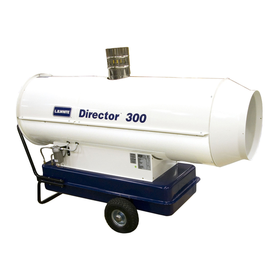
Director
™
MODELS
OUTPUT (Btuh)
CP300CKI
258,700
Construction Heater
FUEL
Kerosene
#1, #2 Diesel/
Fuel Oil,
JP-8 or Jet A
150-28136
Advertisement
Table of Contents

Related Manuals for L.B. White CP300CKI


Summary of Contents for L.B. White CP300CKI
- Page 1 Your new L.B. White heater incorporates the benefits from the most experienced manufacturer of heating products using state-of-the-art technology. We, at L.B. White, thank you for your confidence in our products and welcome any suggestions or comments you may have...call us, toll-free, at (800) 345-7200.
- Page 3 Only properly-trained service people should repair or install this heater. ■ Save this Owner’s Manual for future use and reference. ■ Owner’s Manuals and replacement labels are available at no charge. For assistance, contact L.B. White at 800-345-7200. WARNING WARNING Fire and Explosion Hazard Fire and Explosion Hazard ■...
-
Page 4: Table Of Contents
Have your qualified installer review this manual with you so that you fully understand the heater and how it The L.B. White Co., Inc. has a policy of continuous product functions. improvement. It reserves the right to change specifications... -
Page 5: Heater Specifications
Heater Specifications Model CP300CKI SPECIFICATIONS Kerosene, #1 #2 Diesel/Fuel Oil, JP-8, Jet A Fuel Type Max Input (BTUH) 294,000 Net Output (BTUH) 258,700 Air Flow (Hot) CFM 2,500 Pump Pressure , (PSI) Fuel Tank Capacity (gal.) / Fuel Consumption per Hour (gal.) 27.7/ 2.17... -
Page 6: Safety Precautions
Manual, etc., that is provided with each heater. regulations regarding the safe fueling of heating units. 2. All installations and applications of L.B. White heaters must meet all relevant local, state and national b) Use only the type of fuel specified within the codes. -
Page 7: Installation Instructions
18. When heater is moved or stored, it must be in a level minimum safe distance is 10 f t. It is fur ther position or fuel spillage may occur. recommended that these enclosure materials be of a fire retardant nature. These enclosure materials 19. - Page 8 FIG. 2 VENTING TO EXISTING CHIMNEY FIG. 3 VENTING TO OUTSIDE THROUGH WALL Minimal 3 ft. 1) Anti-wind device provided B) Minimal 3 ft. with the heater C) The shortest 2) Horizontal crossing with minimal upside angle pitch of 5º D) The same or bigger than the stacks outlet 3) Chimney 8 in.
-
Page 9: Operation Instructions
Operation Instructions BASICS OF OPERATION Additionally, the fan is also responsible for pushing the air THE FUEL SYSTEM into and around the combustion chamber. This air is The motor turns the fuel pump. The fuel pump pulls fuel heated and provides a stream of clean, dry, hot air. from the fuel tank. -
Page 10: Connecting Thermostat
CONNECTING THERMOSTAT (Accessory - Part #27508) a) Push latch away from thermostat socket on control FIG. 5 b. panel and remove cover from thermostat socket. See Fig.5a b) Connect thermostat plug to socket. Lock plug to socket using latch. See Fig. 5b. FIG. -
Page 11: Start-Up Instructions
Start-Up Instructions 1. Follow all ventilation and safety information. When in normal operation, the Ignition control reset button with lamp emits a GREEN light. Ensure electrical supply conforms to data plate requirments. When the unit is started for the first time or is started after the fuel tank has been totally emptied, the flow Fill tank with fuel. -
Page 12: Shut-Down Instructions
Shut-Down Instructions 1. Turn thermostat dial to lowest temperature setting. CAUTION This will shut the burner off. The motor will continue to run for 90 seconds. This allows the fan to cool the ■ combustion chamber. When the cooling cycle is Do not unplug the heater while heater is in operation. -
Page 13: Cleaning And Storage Instructions
Cleaning and Storage Instructions WARNING Fire, Burn, and Explosion Hazard ■ This heater contains electrical and mechanical components in the fuel management, and safety systems. ■ Such components may become inoperative or fail due to dust, dirt, wear and aging. ■... -
Page 14: Service Instructions General
Service Instructions GENERAL The high limit, thermostat, and air pressure switch can be tested by disconnecting the leads at the WARNING component, and jumpering the leads together: Burn Hazard ■ Heater surfaces are hot for a period of time after the Reconnect the electrical supply and open fuel heater has been shut down. -
Page 15: Fuel Pump
FUEL PUMP 4. To adjust pressure use 4mm allen wrench at adjustment Removal screw, lower left of the pump, marked “-” and the “+” . 1. Disconnect fuel supply line from pump. Turn the allen head clockwise towards the “+” to increase the pressure. -
Page 16: Setting For High Altitude
SETTING FOR HIGH ALTITUDE Set the air adjustment collar at the burner to compensate for Loosen the wing screw at the burner head and slide the change in altitude. The heater is set from the factory to adjustmewnt collar accordingly to these opening sizes in operate at 1,000 ft. -
Page 17: Photocell
PHOTOCELL 1. Remove the photocell by firmly grasping its body and FIG. 17 pulling it from its holder. See Fig. 17. Ensure tab on photocell body is firmly pushed within slot of holder at reassembly to lock photcell in place Cleaning -- Disconnect photcell from holder. -
Page 18: Air Pressure Switch And Tubing
AIR PRESSURE SWITCH AND TUBING FIG. 21 ■ The air pressure switch is mounted to the inside of a small access panel at the fan end of the heater. See Fig. ■ Ensure the switches flexible tubes and fittings are not blocked with dust/dir t or pinched. -
Page 19: Troubleshooting
Troubleshooting Information Page Problems READ THIS ENTIRE SECTION BEFORE BEGINNING TO Motor does not run, heater does not light....19 TROUBLESHOOT PROBLEMS. Motor runs,heater ignites, emits smoke....19 WARNING ■... -
Page 22: Electrical Connection Diagram
Electrical Connection NEUTRAL AUTO RESET LIMIT SWITCH... -
Page 23: Heater Component Function
Heater Component Function Air Pressure Switch Ignition Transformer Safety device used to insure that the proper air flow is being Receives 120 volts from the ignition module and then achieved as the gas solenoid is opened. boosts it to a very high voltage at the ignitor causing the fuel sprayed from the nozzle to ignite. -
Page 24: Parts Identification
Parts Identification PARTS SCHEMATIC 14 78... -
Page 25: Parts List
PARTS LIST * Bold Item Numbers Indicate Immediate Parts Availability. Item Description Outlet cone 572392 Chimney 150mm 572393 Combustion chamber support 572600 Combustion chamber 572599 Exhaust end upper case 572396 Fan end upper case 572397 Lower case 572598 Motor w/capicitor 572399 Capacitor 80 uF 572601... - Page 26 PARTS LIST (cont.) * Bold Item Numbers Indicate Immediate Parts Availability. Thermostat cap 572365 Power cord 572364 Indicator lamp 572363 Nozzle 572616 Burner disc 572617 Ignitor 572618 Nut, 572619 Nozzle manifold 572620 Burner flange 572621 Ignition cables,high voltage 572622 Fuel line 572355 Photocell 572623...
-
Page 27: Warranty Policy
12 months from date of shipment from L B. White. found to be defective, L.B. White Co., Inc. will at its option, repair or replace the defective part or heater, with a new...
Need help?
Do you have a question about the CP300CKI and is the answer not in the manual?
Questions and answers