Table of Contents
Advertisement
Quick Links
Advertisement
Table of Contents

Related Manuals for Eaton i-on1000EX


Summary of Contents for Eaton i-on1000EX
- Page 1 Security System Installation Guide Issue 2...
- Page 2 © Eaton’s Security Business. 2014 IN NO EVENT WILL EATON’S SECURITY BUSINESS BE LIABLE FOR ANY SPECIAL, CONSEQUENTIAL , OR INDIRECT LOSS OR DAMAGE, INCIDENTAL DAMAGES, STATUTORY DAMAGES, EXEMPLARY DAMAGES, LOSS OF PROFITS, LOSS OF REVENUE, LOSS OF ANTICIPATED SAVINGS, LOSS OF BUSINESS OR OPPORTUNTIY, LOSS OF GOODWILL OR INJURY TO REPUTATION, LIQUIDATED DAMAGES OR LOSS OF USE, EVEN IF INFORMED OF THE POSSIBILITY OF SUCH DAMAGES.
-
Page 3: Table Of Contents
Leaving the Installer Menu ......25 CONTENTS Re-Entering the Installer Menu ..... 25 Defaulting Access Codes ......26 1. Introduction ............. 1 Restoring Factory Defaults at the Control Unit Communications ..........1 ..............26 Partitions ............1 Transferring to Another Keypad ....27 Installer Programming Interface...... - Page 4 This page is intentionally blank. Page iv...
-
Page 5: Introduction
1. Introduction Up device and remote radio keypad. This control unit is designed and approved to be The i-on1000EX is a control unit for a hybrid used as part of a Security Grade 3 system. The wired/wirefree alarm system intended for control unit is also approved to operate as part of domestic, commercial or industrial use. -
Page 6: Installer Programming Interface
Installer menu. Please see the Web Server Setup Guide for more instructions. Note that Eaton’s Security Business recommend using Internet Explorer. Other browsers may not be fully compatible with the built-in web browser interface. -
Page 7: Before You Begin
Within a protected area. Do NOT site the unit: If you intend to fit radio expanders, you should conduct signal strength tests. Eaton’s Security In the entry or exit areas, or outside the area Business produce the Scantronic 790r hand-held covered by the alarm system. -
Page 8: Guided Tour
Guided Tour CAUTION: All printed circuit boards for the i-on1000EX, its expanders and keypads have been tested for Electromagnetic Compatibility (EMC). However, when handling the PCBs you must take the standard precautions for handling static-sensitive devices. - Page 9 Before You Begin 1. Case back. 2. Cable entry holes for loudspeakers, siren/strobes and communicators. 3. Fixing holes. 4. Plastic PCB tray. 5. Printed Circuit Board (PCB). 6. Cable entry holes for detector and keypad wiring. 7. Hole for back tamper fitting.
-
Page 10: Keypads
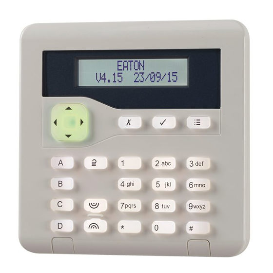
Before You Begin i-on1000EX Keypads i-kp01 Controls and Displays 2 abc 3 def 4 ghi 5 jkl 6 mno 7 pqrs 8 tuv 9 wxyz 1. Central keyhole. 2. Rear tamper shroud. 1. LCD display (2 x 20 characters). 3. Cable entry. - Page 11 Before You Begin KEY-K01/KP01/KPZ01 Controls and Displays 2 abc 3 def Figure 9 Opening the Keypad 4 ghi 5 jkl 6 mno 7 pqrs 8 tuv 9 wxyz 1. LCD display 2. Programming keys. 3. Navigation keys. This key has built-in alert LEDs.
-
Page 12: Expanders
Before You Begin i-on1000EX BRIGHT TERM Z1 Z2 0V 12V D0 D1 LED 0V 12V A EXT READER 1. Tamper switch. 1. Tamper switch. 2. Sounder. 2. Sounder. 3. Connector for KEY-EP. 3. Connector for KEY-EP. Terminals for 4. Sounder volume control. - Page 13 Before You Begin 1. Cable entry (also behind PCB). 2. Central keyhole. 3. PCB. 4. Relay card (i-rc01) connector. 5. Aux power. 6. Link to enable/disable front/rear tamper switch. 7. Lid tamper (rear tamper behind pcb). 8. Zone connectors 9.
-
Page 14: Power Availability
12V. The following calculation shows a simplified example in an alarm system with an i-on1000EX Screened cable may prove necessary if the control unit, five i-kp01 keypads, three expanders... -
Page 15: Bus Termination
Bus Termination voltage at each device must NOT drop below 10.5V even when running on the standby battery. The i-on1000EX bus uses the RS485 interface. Eaton’s Security Business recommend that the Because of this, the ends of the line in some voltage at each device should stay above 12V. - Page 16 The supply must two. have a "floating zero volt rail" if connected to the bus, otherwise an earth fault will occur. Eaton’s Reducing Voltage Drop - Method 2: Security Business recommend the EXP-PSU. Supply the detection devices from the Aux output When installing a remote power supply, fit it close on separate cores.
-
Page 17: Installation
Fitting tamper Shroud 3. Installation The tamper shroud is intended to prevent an intruder sliding a tool between case and wall to Note: The installation steps listed below assume interfere with the tamper bracket. When fitted, the that you have already decided on the required... -
Page 18: Step 2. Run Bus Cable
Installation i-on1000EX 1. Hold the backplate in place against the wall and mark the position of the hole in the tamper block (see Figure 23). 2. Drill and plug the hole, and screw the backplate to the wall through the tamper block using the screw provided. -
Page 19: Keypad Addressing
Installation Keypad Addressing b) Enter a local keypad programming mode (this replaces the use of jumpers on the keypad The control unit assigns addresses to all devices PCB in the i-kp01). connected to the bus cable. If you wish, you can... - Page 20 Installation i-on1000EX disabled, and will not 3. Press repeatedly to select glow for any fault reports. one of the following: MENU 4. Leave local programming Backlight LEDs ON (). BACKLIGHT mode and save your MENU Backlight timed ().
-
Page 21: Tone Volume - All Keypads
Installation 2.Tilt the edge of the fixing plate and then slide it a Figure 28 shows the wiring connections at the short distance parallel to the body of the prox keypad. reader. 3. Slide the fixing plate away from the reader body, along the cable. -
Page 22: Connecting An Expander To The Bus
Installation i-on1000EX Connecting an Expander to the Bus Both wired and radio expanders provide a connector for the bus at the bottom of their PCBs. Control Unit Expander +12V 12V AUX 0V +12V A To next device Figure 29 Wiring Expanders... -
Page 23: Two-Wire Closed Circuit Connections
Installation KEY-KPZ01 Figure 35 shows The wiring connections for FSL zones on the EXP-WCC. Tamper Zone 1 Alarm Zone 1 Figure 33 KEY-KPZ01 CCL Zone Wiring Two-Wire Closed Circuit Connections On the EXP-W10, you can connect two-wire CCL detectors to each pair of zone terminals. To specify the zone wiring type, use Installer menu –... -
Page 24: Step 7. Connect Wired Outputs
Installation i-on1000EX between the outer terminals. The inner (shaded) Wired External Sounders (Optional) terminal is not connected, and provides a spare Wired external sounders differ in their methods of terminal. connection. Figure 41 shows an example of a general method of using the outputs to connect a wired sounder. -
Page 25: Wired External Sounders On Expanders
OR a 4k7 resistor if using 4k7/4k7 FSL. Do not use any other FSL resistor combinations. Figure 42 Using Wired Expander Outputs. CC wiring Eaton’s Security Business does NOT Wired External Sounders on Expanders recommend that you use CC wiring for this application. -
Page 26: Output On Key-Kpz01
Installation i-on1000EX Com Connector Cable, tamper switch in the loudspeaker to the control Part number 485210 unit. 12V (Red) Expanders provide connections for only one 0V (Black) loudspeaker. Do not connect another loudspeaker (Not used) (White/Orange) in parallel. You may connect another loudspeaker... -
Page 27: Step 9. Fit And Connect Battery
Installation Line Fail Input Connect the battery leads, red to the positive, This input is designed to allow a plug-by black to the negative terminals of the battery. communicator to indicate to the control unit that Connect the other ends of the leads to either the communications link has failed. - Page 28 Installation i-on1000EX The address is now stored in the keypad. the "Lid/Back Tamper" link is not fitted. Keypads take bus device addresses 51 upwards. Please refer to the Engineering Guide for details of bus addressing. If you see the above, enter the default installer access code ("7890"...
-
Page 29: Leaving The Installer Menu
Installation The control unit assigns the next free address 4. Either: Press to go back into Installer menu and displays it on the two-digit LED display. (so that you can go and check that all the bus If you do not want to use the address shown,... -
Page 30: Defaulting Access Codes
Installation i-on1000EX if you have not been in the Installer menu or 6. Remove the short from the Reset Codes pins. set factory defaults within the last half-hour. 7. Reconnect the battery. This period of grace is returned to zero if the 8. -
Page 31: Transferring To Another Keypad
Installation LEDs On Control Unit PCB 5. EITHER: Press if you do not want to pair There are several LEDs on the PCB that show the buses (see page 1). functioning of various parts of the control unit: OR: Press ... -
Page 32: Program The System
Program the System Program the system to suit user requirements. Page 29 contains a summary of the Installer menu on the i-on1000EX. Please see the Engineering Guide for a more detailed description. Note: make sure that you allocate keypads correctly to partitions. For more information, see “Assigning Wired Keypads to Partitions”... -
Page 33: Installer Menu
Installer Menu Name Tamp as Tamp-Only Line Fail Delay 1 DETECTORS/ DEVICES Exit mode Confirmation (-EUR IP Network (Own) Detectors Settle time version) Web Server Add/Del Detectors Exit time Sounder on Status Program Zones Entry time Siren on Port Number... - Page 34 Appears only when Report Type = Fast Format AND Confirmation Mode = Basic Shows “None” if no module fitted. Must be activated by a Eaton’s Security Business External Support Manager. Table 2. Menu Options Available with Communications Modules With Communications Module...
-
Page 35: Maintenance
Product 1000 zone endstation with Check the keypads for obvious signs of Description remote keypads. damage. Eaton’s Security Business. Manufacturer Test the action of all buttons on all keypads. Environmental Class II. Clean the keypad surface and display. To Operating Tested -10 to +55°C. -
Page 36: Security
The i-on1000EX has a "pair buses" feature (e.g. in total than an average of 1.1A over a 30-hour to pair buses 0 and 1). This enables a bus to standby time. -
Page 37: Electromagnetic Compatibility
Other Max p-to-p ripple 0.5V voltage: If you wish to connect the i-on1000EX control unit Standby Battery: 12V, 17Ah sealed lead to a PC using either the Ethernet or the USB port, acid, 2 off (not supplied). make sure that the cables have the following ‘Low battery’... -
Page 38: Compliance Statements
Combined door contact The i-on1000EX is compliant with EN50130-5 shock sensor transmitter environmental class II. XCELR Radio PIR The i-on1000EX is suitable for use in systems XCELRPT Pet-tolerant radio PIR designed to comply with PD 6662: 2010 at grade XCELW Wired PIR... - Page 39 NOTES: Page 35...
- Page 40 Product Support (UK) Tel: +44 (0) 1594 541978. Available between: 08:30 to 17:00 Monday to Friday. Product Support Fax: (01594) 545401 email: techsupport@coopersecurity.co.uk Part Number 12480675 11th November 2014 Page 36...
Need help?
Do you have a question about the i-on1000EX and is the answer not in the manual?
Questions and answers