
Related Manuals for Xantrex Freedom Xi 807-1000


Summary of Contents for Xantrex Freedom Xi 807-1000
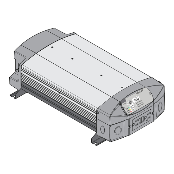
- Page 1 Installation Guide Product image shown may vary from actual product. See features for comparisons. Freedom Xi Inverter Model Product Numbers 807-1000 807-2000...
-
Page 3: Contact Information
MAKES NO WARRANTY AS TO THE ACCURACY SUFFICIENCY OR SUITABILITY OF ANY +1 408 987 6030 TECHNICAL OR OTHER INFORMATION PROVIDED IN ITS MANUALS OR OTHER DOCUMENTATION Web: www.xantrex.com ASSUMES NO RESPONSIBILITY OR LIABILITY FOR LOSSES DAMAGES COSTS OR EXPENSES WHETHER SPECIAL... - Page 4 Related Information • Applying all applicable installation codes. • Analyzing and reducing the hazards involved in performing electrical You can find more information about Xantrex products and services at work. www.xantrex.com. • Selecting and using Personal Protective Equipment (PPE). Freedom Xi Installation Guide...
-
Page 5: Important Safety Instructions
Important Safety Instructions DANGER IMPORTANT: R EAD AND SAVE THIS NSTALLATION DANGER indicates an imminently hazardous situation, which, if not UIDE FOR FUTURE REFERENCE avoided, will result in death or serious injury. This guide contains important safety instructions for the Freedom Xi Sine WARNING Wave Inverter that must be followed during operation and troubleshooting. -
Page 6: Safety Information
Safety Information Before using the inverter, read all instructions and cautionary Do not expose this unit to rain, snow, or liquids of any type. This markings on the unit, the batteries, and all appropriate sections of product is designed for indoor use only. Damp environments will this manual. - Page 7 DANGER WARNING HAZARD OF ELECTRIC SHOCK, EXPLOSION, OR ARC FLASH FIRE AND EXPLOSION HAZARD • Apply appropriate personal protective equipment (PPE) and follow • Unit’s components may produce arcs or sparks. safe electrical work practices. See NFPA 70E or CSA Z462. •...
- Page 8 NOTES: CAUTION Follow these instructions and those published by the battery ELECTRICAL SHOCK AND FIRE HAZARD manufacturer and the manufacturer of any equipment you intend to use • Do not open. No serviceable parts inside. Provided with integral in the vicinity of the battery. Review cautionary markings on these protection against overloads.
-
Page 9: Precautions When Working With Batteries
Precautions When Working With Batteries Use extra caution to reduce the risk of dropping a metal tool on the battery. It could spark or short circuit the battery or other electrical parts and could cause an explosion. Battery work and maintenance must be done by qualified Important: personnel knowledgeable about batteries to ensure compliance with battery Batteries can produce a short circuit current high enough to weld a ring... - Page 10 Precautions When Placing the Inverter Regulatory The Freedom Xi Sine Wave Inverter is certified to appropriate US and WARNING Canadian standards. For more information see “Regulatory Approvals” on page 33. FIRE HAZARD The Freedom Xi Sine Wave Inverter is intended to be used for mobile or Do not install the inverter or any part of its supplied wiring in engine commercial applications.
- Page 11 FCC Information to the User This equipment has been tested and found to comply with the limits for a Class B digital device, pursuant to part 15 of the FCC Rules. These limits are designed to provide reasonable protection against harmful interference in a residential installation.
-
Page 13: Table Of Contents
Contents Important Safety Instructions ..................iii Materials List. -
Page 15: Materials List
(not shown) • one set of lock washers and nuts (not shown) any of the items are missing, contact Xantrex or any NOTE: If authorized Xantrex dealer for replacement. See “Contact Owner’s and Installation Guides Information”... -
Page 16: Safety Instructions
Safety Instructions Before You Begin the Installation Installation Codes Before beginning your installation: Governing installation codes vary depending on the specific location and application of the installation. Some examples include • Read the entire Installation Guide so you can plan the the following: installation from beginning to end. -
Page 17: Installation Tools And Materials
Installation Tools and Materials You will need the following to install the Freedom Xi: ❐ Wire stripper ❐ Mounting screws or bolts ❐ #2 Phillips screwdriver ❐ 3.5mm slot long neck screwdriver for WAGO terminals ❐ Wrench for DC terminals (1/2" or adjustable) ❐... -
Page 18: High Level Overview Of Installation Steps
High Level Overview of Installation Steps Installing the Freedom Xi includes the following steps. Ensure that power sources are OFF, like opening the DC disconnect switch and opening circuit breakers on the AC source panel. Mount the inverter securely and permanently in one of the acceptable orientations. -
Page 19: Basic Installation Procedures
Basic Installation Procedures This section provides sample installation information as a guide for your installation. For your convenience, the overall procedure is divided into these main steps: ❐ Step 1: Designing the Installation on page 6 ❐ Step 2: Choosing a Location for the Unit on page 12 ❐... -
Page 20: Step 1: Designing The Installation
Basic Installation Procedures Step 1: Designing the Installation Most Freedom Xi installations share common components, and some of these are briefly described in Figure 2. Equipment Ground Figure 2 shows some components and their relationship to each other in a typical recreational vehicle or fleet vehicle installation. Also, see “Marine Installation”... - Page 21 Basic Installation Procedures AC Shore Power Xi input must be sized adequately to carry current up to the rating of the input breaker and in accordance with the electrical codes or A source of 120 volts AC 60Hz sine wave alternating current regulations applicable to your installation.
- Page 22 Basic Installation Procedures AC Cabling AC Distribution Panels AC cabling includes all the wires and connectors between the AC Most systems incorporate distribution centers both ahead of the source and the Freedom Xi, as well as all cabling between the Freedom Xi (the AC source panel) and between the Freedom Xi and Freedom Xi and the AC output panels, circuit breakers, and loads.
-
Page 23: Ac Output Neutral Bonding
Basic Installation Procedures AC Output Neutral Bonding AC Grounding The neutral conductor of the Freedom Xi’s AC output circuit (that As per UL458 SA29.5, for all permanently connected marine is, AC Output Neutral) is automatically connected to the safety inverters: The Freedom Xi models should be connected to a ground during inverter operation. - Page 24 Basic Installation Procedures DC Cabling Table 2 Recommended Cable and Fuse Sizes This includes all the cables and connectors between the batteries, Cable Length: Maximum the DC disconnect and over-current protection device, and the Battery to Inverter Minimum battery Fuse Inverter (one way) Cable Size...
- Page 25 Basic Installation Procedures DC Disconnects and Over-Current Devices Ground Fault Circuit Interrupters (GFCIs) The DC circuit from the battery to the Freedom Xi must be A GFCI is a device that de-energizes a circuit when a current to equipped with a disconnect and over-current device. This usually ground exceeds a specified value that is less than that required to consists of a circuit breaker, a “fused-disconnect”, or a separate fuse blow the circuit breaker.
-
Page 26: Step 2: Choosing A Location For The Unit
Basic Installation Procedures Step 2: Choosing a Location for the Unit around the unit, the better the performance. Do not allow the WARNING ventilation openings on the ends of the unit to become obstructed. FIRE AND EXPLOSION HAZARDS ❐ Safe. Do not install the Freedom Xi in the same compartment •... -
Page 27: Step 3: Mounting The Unit
Basic Installation Procedures Step 3: Mounting the Unit To mount the Freedom Xi: See page 30 for drip Remove the Freedom Xi from its shipping container, verify that shield installation on all components are present, and record relevant product Marine applications. information on “Information About Your System”... -
Page 28: Connecting The Equipment Ground
Basic Installation Procedures Connecting the Equipment Ground Grounding Locations You must connect the equipment ground stud to a grounding WARNING point—usually the vehicle’s chassis or DC negative bus ground— using recommended copper wire (if insulated then green insulation FIRE HAZARD with or without one or more yellow stripes) or larger. -
Page 29: Step 4: Connecting The Ac Input Wires
Basic Installation Procedures Step 4: Connecting the AC Input Wires AC Wiring and GFCIs You can plug loads, 15 amps for 1000- WARNING watt models and 20 amps for 2000-watt models, directly into the GFCI receptacle on the front panel of the Freedom Xi. You can also FIRE, SHOCK, AND ENERGY HAZARDS connect the inverter to an existing AC installation and then plug Make sure wiring is disconnected from all electrical sources before... - Page 30 Basic Installation Procedures Table 4 Required AC wire size vs. required breaker rating Table 5 Color codes for typical AC wiring Required Breaker Size (amps) Required Wire Size Color AC Wire Black Line Freedom Xi 1000 30 A maximum 10 AWG 120VAC White Neutral...
- Page 31 Basic Installation Procedures AC Input Connections for Standard Models NOTICE clamp slot 10mm REVERSE POLARITY DAMAGE Make sure the wires are connected properly. Improper connections (connecting a line conductor to a neutral conductor, for example) will cause the Freedom Xi to malfunction and may permanently damage the to circuit inverter.
-
Page 32: Step 5: Connecting Ac Output To An Existing Ac Circuit
Basic Installation Procedures Step 5: Connecting AC Output to an Existing AC Circuit A manufacturer-tested and approved GFCI must be connected to the WARNING Freedom Xi AC output, and on every receptacle connected to the AC hard wired installation. Other types may fail to operate properly FIRE, SHOCK, AND ENERGY HAZARDS when connected to the Freedom Xi. - Page 33 Basic Installation Procedures AC Output Connections for the Standard Models To make a permanent connection to existing AC wiring: 10mm clamp slot terminal opening to circuit breaker Ensure AC and DC power sources are turned off. Install the required circuit breaker in the inverter distribution panel receiving AC power from the inverter.
-
Page 34: Step 6: Connecting The Dc Cables
Basic Installation Procedures Step 6: Connecting the DC Cables The following instructions only apply to the standard models. Do not route your DC cables through an electrical distribution panel, battery isolator, or other device that will cause additional voltage drops. NOTICE Figure 5 shows the DC end for your reference. - Page 35 Basic Installation Procedures Strip 1/2 inch (13 mm) to 3/4 inch (19 mm) insulation from one • be as close to the battery positive terminal as possible end of each cable. The amount stripped off will depend on the • be rated for DC circuits terminals chosen.
- Page 36 Basic Installation Procedures NOTICE ring terminal DC terminal REVERSE POLARITY DAMAGE Check cable polarity at both the battery and the Freedom Xi before making the final DC connection. Positive must be connected to positive; negative must be connected to negative. Reversing the positive and negative battery cables will blow a fuse in the Freedom Xi and void your warranty.
- Page 37 Basic Installation Procedures 13. Connect the cable from the negative post of the battery to the Marine Use copper wire that is bare or has insulation rated negative DC terminal of the inverter. minimum 105 °C, and connect it between the Chassis Ground lug and the boat’s DC grounding bus or engine negative bus.
- Page 38 Basic Installation Procedures Locate the vehicle's ignition control wire from the vehicle’s ignition circuit. This wire must be fused appropriately at no more than five amps. Refer to the vehicle’s user manual for guidance. Using a #1 Phillips screw driver, remove the screw securing the DC wiring cover on the left hand side of the unit.
- Page 39 Basic Installation Procedures Remove the DC wiring cover to expose the ignition control Ignition Lock- In this position, when ignition voltage is terminals of the DC wiring compartment. detected at the ignition input terminal, inverter Move the jumper wire from the left-side position (factory mode remains on "standby"...
-
Page 40: Step 7: Mounting The Display Panel
Basic Installation Procedures Step 7: Mounting the Display Panel The communications cable supplied with the display panel is 25 feet To mount the display panel: (7.6 meters) long. If you want to replace the cable with one that is Choose a location that is dry, out of direct sunlight, free from shorter, use a high quality, six-wire telephone extension cable. -
Page 41: Step 8: Testing Your Installation
Basic Installation Procedures Step 8: Testing Your Installation Testing in Invert Mode WARNING To test the Freedom Xi in invert mode: ELECTRICAL SHOCK HAZARD For hard wired installations, ensure shore power is not present. Pressing the Inverter button to turn OFF the Freedom Xi inverter function Press the Inverter button to turn the inverter on. -
Page 42: Testing In Shore Power Mode
Basic Installation Procedures Testing in Shore Power Mode To test the Freedom Xi in shore power mode: ◆ With the appliance from the previous test still connected and operating, connect the shore power source. The Freedom Xi transfers the appliances to shore power. The status LED on the display panel will change from yellow to a ten-second flashing yellow and then green. -
Page 43: Marine Installation
Marine Installation Figure 9 illustrates a typical marine installation with the following components: AC power supplied from a shore power connector An AC source panel that includes a Max 30A circuit breaker that supplies the Freedom Xi An AC load panel with branch circuit breakers that supply only loads that run off the Freedom Xi Engine negative bus / DC ground bus DC Fuse /... - Page 44 Marine Installation Drip Shield Installation Different Views The drip shields help to protect the unit from dripping or splashing liquids, which will cause a shock hazard when moisture comes in contact with electrical circuits in the unit. The drip shields are especially useful in marine installations where water from condensation, rain, or sea may come into contact with the Freedom WARNING...
- Page 45 Marine Installation To install the drip shields: Gather the four screws needed to fasten a single drip shield to a wall. Locate an appropriate setting for the drip shields above the Freedom Xi making sure you cover the entire width of the unit. You can overlay the shields as shown in Figure 11 below.
-
Page 46: Specifications
Specifications NOTE: Specifications are subject to change without prior notice. Physical Specifications Freedom Xi 1000 Freedom Xi 2000 L × W × H 19.2” (487mm) × 9.4” (240mm)× 4.7” (120mm) 19.2” (487mm) × 9.4” (240mm)× 4.7” (120mm) Net Weight 11 lbs (5 kg) 14.4 lbs (6.5 kg) Environmental Specifications Freedom Xi 1000... - Page 47 Specifications DC Input Freedom Xi 1000 Freedom Xi 2000 Operating voltage range for all models 10.5–16.5 VDC (low limit) 10.5–16.5 VDC (low limit) 11.8–16.5 VDC (mid limit) 11.8–16.5 VDC (mid limit) 12.1–16.5 VDC (high limit) 12.1–16.5 VDC (high limit) Safe non-operating voltage range 0–24 VDC 0–24 VDC Nominal voltage for all models...
- Page 48 Specifications Dimensions for Mounting 19.2” (487mm) 15.2” (386mm) 9.4” (240mm) 8.9” (225mm) Freedom Xi Installation Guide...
- Page 50 Schneider Electric Solar Inverters USA Inc. +1 800 670 0707 +1 408 987 6030 www.xantrex.com 975-0753-01-01 Printed in China...
Need help?
Do you have a question about the Freedom Xi 807-1000 and is the answer not in the manual?
Questions and answers