Table of Contents
Advertisement
Quick Links
Advertisement
Table of Contents

Subscribe to Our Youtube Channel
Related Manuals for Stairville PAR64 10MM UV


Summary of Contents for Stairville PAR64 10MM UV
- Page 1 PAR64 10MM UV LED PAR user manual...
- Page 2 Musikhaus Thomann e.K. Treppendorf 30 96138 Burgebrach Germany Telephone: +49 (0) 9546 9223-0 E-mail: info@thomann.de Internet: www.thomann.de 25.09.2014, ID: 276113...
-
Page 3: Table Of Contents
Connections and operating elements................... 18 Operation..............................21 7.1 Starting up the device........................21 7.2 Main menu............................21 7.3 Menu overview..........................26 7.4 Functions in 2-channel DMX mode................... 27 Technical specifications........................28 Troubleshooting............................29 Protecting the environment......................31 PAR64 10MM UV... -
Page 4: General Notes
General notes General notes This user manual contains important information on safe operation of the device. Read and follow all safety notes and all instructions. Save this manual for future reference. Make sure that it is available to all persons using this device. If you sell the device to other users, be sure that they also receive this manual. - Page 5 NOTICE! This combination of symbol and signal word indicates a pos‐ sible dangerous situation that can result in material and environmental damage if it is not avoided. Warning signs Type of danger Warning – high-voltage. PAR64 10MM UV...
- Page 6 General notes Warning signs Type of danger Warning – suspended load. Warning – danger zone. LED PAR...
-
Page 7: Safety Instructions
Choking hazard! Ensure that children do not detach any small parts (e.g. knobs or the like) from the unit. They could swallow the pieces and choke! Never let children unattended use electrical devices. PAR64 10MM UV... - Page 8 Safety instructions DANGER! Electric shock caused by short-circuit Do not modify the mains cable or the plug. Failure to do so could result in electric shock/death or fire. If in doubt, seek advice from a registered electrician. DANGER! Electric shock caused by high voltages inside Within the device there are areas where high voltages may be present.
- Page 9 Keep the device away from naked flames. NOTICE! Operating conditions This device has been designed for indoor use only. To prevent damage, never expose the device to any liquid or moisture. Avoid direct sunlight, heavy dirt, and strong vibrations. PAR64 10MM UV...
- Page 10 Safety instructions NOTICE! Power supply Before connecting the device, ensure that the input voltage (AC outlet) matches the voltage rating of the device and that the AC outlet is protected by a residual current circuit breaker. Failure to do so could result in damage to the device and possibly injure the user.
-
Page 11: Features
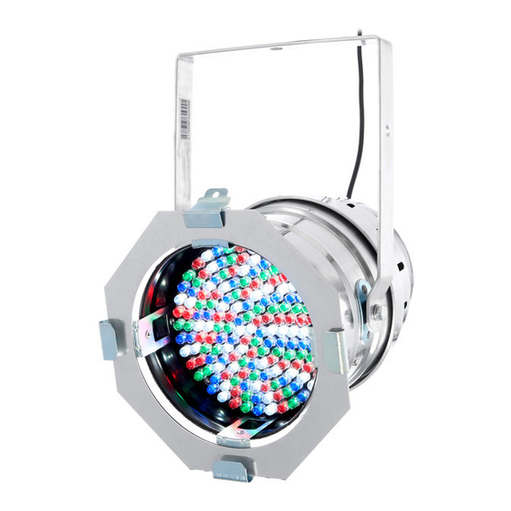
168 × UV LEDs Operation in stand-alone, master / slave or DMX mode Very simple operation via buttons and display on the unit Robust metal housing with detachable grille Ideal for clubs, bars, stages, exhibitions and many more applications PAR64 10MM UV... -
Page 12: Installation
Installation Installation Unpack and carefully check that there is no transportation damage before using the unit. Keep the equipment packaging. To fully protect the device against vibration, dust and moisture during transportation or storage use the original packaging or your own packaging material suitable for transport or storage, respectively. - Page 13 Possible data transmission errors For error-free operation make use of dedicated DMX cables and do not use ordi‐ nary microphone cables. Never connect the DMX input or output to audio devices such as mixers or ampli‐ fiers. PAR64 10MM UV...
- Page 14 Installation DMX connections The unit offers a 3-pin XLR socket for DMX output and a 3-pin XLR plug for DMX input. Please refer to the drawing and table below for the pin assignment of a suitable XLR plug. Configuration Ground, shielding Signal inverted (DMX–, ‘cold signal’) Signal (DMX+, ‘hot signal’) LED PAR...
-
Page 15: Starting Up
Starting up Starting up Establish all connections as long as the unit is switched off. Use the shortest possible high- quality cables for all connections. PAR64 10MM UV... - Page 16 Starting up Connections in DMX mode Connect the DMX input of the device to the DMX output of a DMX controller or another DMX device. Connect the output of the first DMX device to the input of the second one, and so on to form a daisy chain.
- Page 17 Connect the DMX output of the master device to the DMX input of the first slave device. Then connect the DMX output of the first slave device to the DMX input of the second slave device and so on. PAR64 10MM UV...
-
Page 18: Connections And Operating Elements
Connections and operating elements Connections and operating elements Rear panel LED PAR... - Page 19 3 [OK] button Confirms a selected value. 4, 5 , buttons Increases / decreases the displayed value by one. 6 Power chord. 7 [M] button Activates the main menu or a submenu. 8 Bracket for hanging or setting up. PAR64 10MM UV...
- Page 20 Connections and operating elements 9 DMX IN DMX input. 10 DMX OUT DMX output. LED PAR...
-
Page 21: Operation
[OK] to enter the respective submenu or to confirm a new value. To return to the previous menu level without changes, press [M] (for menu structure see Ä Chapter 7 ‘Opera‐ tion’ on page 21). PAR64 10MM UV... - Page 22 Operation DMX address Press [M]. Press one of the arrow keys repeatedly until the display ‘DMX’ . Press [OK]. Now you can set the number of the first DMX channel to be used by the device (DMX address). Use the arrow keys to select a value between 1 and 512 (the display shows ‘A001’...
- Page 23 This setting is only relevant if the device is operated as slave by a master, but is not controlled via DMX. When the display shows the desired value, press [OK] to confirm the selection. Then press [M] to return to the higher menu level. To return to the higher menu level without changes, press [M]. PAR64 10MM UV...
- Page 24 Operation Programme speed Press [M]. Press one of the arrow keys repeatedly until the display shows ‘SET’ . Press [OK]. Press one of the arrow keys repeatedly until the display shows ‘SPEER’ . Press [OK]. Now you can set the programme speed for the preprogrammed automatic shows. Use the arrow keys to select a value between 1 and 255 (the display shows ‘T001’...
- Page 25 This setting is only relevant if the device is not controlled via DMX. When the display shows the desired value, press [OK] to confirm the selection. Then press [M] to return to the higher menu level. To return to the higher menu level without changes, press [M]. PAR64 10MM UV...
-
Page 26: Menu Overview
Operation 7.3 Menu overview LED PAR... -
Page 27: Functions In 2-Channel Dmx Mode
Operation 7.4 Functions in 2-channel DMX mode Channel Value Function 0…255 Dimmer (0 % to 100 %) 0…255 Strobe effect (0 % to 100 %) PAR64 10MM UV... -
Page 28: Technical Specifications
Technical specifications Technical specifications Illuminant 168 × 10 mm LEDs (UV: 400 … 410 nm) Number of DMX channels Operating voltage supply AC 230 V , 50 Hz Power consumption 10 W Dimensions (W × D × H) 275 mm × 325 mm × 275 mm Weight 2.1 kg LED PAR... -
Page 29: Troubleshooting
Never connect the DMX input or output to audio devices such as mixers or ampli‐ fiers. In the following we list a few common problems that may occur during operation. We give you some suggestions for easy troubleshooting: PAR64 10MM UV... - Page 30 Troubleshooting Symptom Remedy The unit does not work, no Check the mains connection and the fuse. light. No response to the DMX con‐ 1. Check the DMX ports and cables for proper connection. troller. 2. Check the address settings and the DMX polarity. 3.
-
Page 31: Protecting The Environment
Dispose of this device through an approved waste disposal firm or through your local waste facility. When discarding the device, comply with the rules and regulations that apply in your country. If in doubt, consult your local waste disposal facility. PAR64 10MM UV... - Page 32 Notes LED PAR...
- Page 33 Notes PAR64 10MM UV...
- Page 34 Notes LED PAR...
- Page 36 Musikhaus Thomann e.K. · Treppendorf 30 · 96138 Burgebrach · Germany · www.thomann.de...
Need help?
Do you have a question about the PAR64 10MM UV and is the answer not in the manual?
Questions and answers