
Subscribe to Our Youtube Channel
Related Manuals for VideoRay Pro 4


Summary of Contents for VideoRay Pro 4
- Page 1 Version: 1.07.00 Copyright © 2012, VideoRay LLC - The Global Leader in Micro-ROV Technology...
- Page 2 This material is copyright protected. No material may be reproduced or transmitted in any form or by any means for any purpose without expressed written consent of VideoRay LLC. Copyright © 2012, VideoRay LLC - The Global Leader in Micro-ROV Technology...
-
Page 3: Table Of Contents
..10 General FAQ ..15 Pro 4 Overview ..17 Quick Start Instructions ..18 Safety First . - Page 4 ..87 Miscellaneous ..88 VideoRay Cockpit Guide ..89 Video Window ..90 Video Text Overlay .
- Page 5 Water Temperature ..124 Turns Indicator ..125 Accessory Instruments ..126 Manipulator/Cutter ..127 Lateral Thruster .
- Page 6 Auto Depth ..184 Auto Heading ..186 Low Visibility ..187 Swift Current ..189 Deep Water .
- Page 7 Sensors ..239 Cathodic Protection Probe ..240 C3 Fluorometer ..241 Laser Scaling Device ..242 METS Methane Sensor .
-
Page 8: About This Documentation
About this Documentation The VideoRay Pro 4 has sophisticated features, but is easy to use and maintain once you learn its capabilities and the proper operating techniques. This documentation will guide you through your first dive and provide additional details to help you learn all aspects of its operation. - Page 9 We have made every effort to ensure that this documentation is accurate and provides you with the most effective means to learn how to use your new Pro 4. However, there is no substitute for experience and/or training, especially with respect to the real purpose for which you plan to use this equipment. We encourage you to explore options beyond the scope of these materials to expand your knowledge and skills necessary to support your application.
-
Page 10: Glossary
Glossary Accelerometer - A device used to measure acceleration - used to determine pitch and roll of the ROV Accessory - An optional device that can be used with the VideoRay system to augment its features and capabilities Accessory Port - ROV connection for ROV mounted accessories that provides access to power and data... - Page 11 Computer - Primary topside component required to run VideoRay Cockpit Control Bar - A VideoRay Cockpit feature that provides access to several functional areas of the software Control Panel - The surface component that provides power and communications with the ROV...
- Page 12 IEC - (International Electrotechnical Commission) Power cord connector standard Import - Method to receive and process data from other systems Instrument - VideoRay Cockpit interface feature to display information or control features Instrument Display - The ability to set an instrument's opacity or turn it on or off...
- Page 13 Sensor - An instrument for measuring a specific property of an object or the environment Service Bay - VideoRay Cockpit interface that provides diagnostic information and checklists Settings - The values of specific controls or parameters, or the ability to manage these...
- Page 14 VGA - Video Graphics Array) Video format and connector style Video - In VideoRay context, the image from the ROV's camera or the ability to record this image Video Encoder - Defines a method of storing a video image within a file format...
-
Page 15: General Faq
How hard is it to learn how to operate the Pro 4? The Pro 4 is easy to learn to operate. In a few hours, user should be able to pilot the ROV confidently in clear, calm water and know enough about it to maintain it in good condition for years. However, mastering all the knowledge and developing the skills to be able to pilot the ROV in much more demanding situations with near zero visibility and swift current will require more experience. - Page 16 Can you export data from the Pro 4? Data from the VideoRay Pro 4 sensors can be exported to other systems via a COM port in real time or a file for post processing. See the Data Export...
-
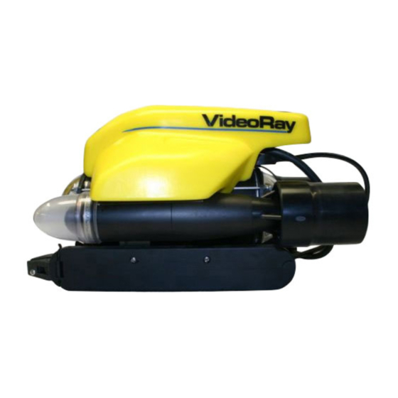
Page 17: Pro 4 Overview
VideoRay is pleased to present the latest model in its top-of-the line professional series Micro-ROVs - the VideoRay Pro 4. Like the Pro 3, the Pro 4 was designed for performance and maintainability, but has entirely new internal electronics, including camera, LED lights, processor, and added sensors. With powerful brushless motors, the Pro 4 further extends VideoRay's position as the fastest and most powerful tether pulling vehicle. -
Page 18: Quick Start Instructions
Pro 4. While you will likely find the Pro 4 easy to pilot, we strongly recommend that your first dive be conducted in a controlled environment such as a small tank or pool. As you gain experience with your system and confidence in using it, you will be able to operate in more challenging conditions that might include low visibility, currents and potential hazards that could snag your tether or trap your ROV. -
Page 19: Safety First
Have proper safety equipment, such as PFDs (Personal Flotation Devices), on hand and make sure you know how to use them before you need them. Keep fingers, hair, loose clothing and other objects away from VideoRay's propellers. Be aware of and follow any legal ordinances or regulations in your area regarding operation of vessels and underwater equipment in the water. -
Page 20: System Components
Hand Controller The hand controller is used to pilot the VideoRay and operate other features like the lights, camera controls and manipulator. The hand controller is pre-programmed, but can be customized to meet specific user or operational needs. -
Page 21: Pre-Dive Preparations
Conduct a Visual Inspection Assuming this is your first time using the VideoRay, everything should be in proper working order and ready to go, but it is good practice to perform a pre-dive inspection before every dive, even your first. If any problems are... - Page 22 Turn on the computer and wait for the system to complete the boot up process. After the computer has started, start VideoRay Cockpit using the desktop icon, or by selecting it from the Start->All Programs->VideoRay menu.
- Page 23 VideoRay Cockpit screen with simulated video image - your image will likely be different. Testing the System's Functions The next step is to ensure that the essential features of the ROV are functioning properly. Use the hand controller to perform the following tests. See the...
- Page 24 Press and hold the Camera Tilt Up button - the camera should tilt up smoothly through its entire range. Press and hold the Camera Tilt Down button - the camera should tilt down smoothly through its entire range. Press and hold the Camera Focus In button - the camera should focus in smoothly through its entire range.
-
Page 25: Dive Operations
VideoRay is to check the buoyancy. For most operations, the buoyancy is optimal when the top of the float block is even with the water surface and the ROV is level. If the ROV is to buoyant or heavy, the vertical position may be hard to maintain or control. -
Page 26: Post-Dive Operations
Equipment Maintenance guides. If you still have difficulty or questions, contact VideoRay. Your success is our success, and we are here to help you get the most out of your VideoRay. VideoRay contact information is available in the About this Documentation... -
Page 27: Equipment Guide
Equipment Guide Understanding the features and capabilities of the Pro 4 equipment is essential to get the most value out of using the system. The sections within this Equipment Guide provide details about each of the components. Topics in this Section... -
Page 28: Rov
The Pro 4 ROV (Remotely Operated Vehicle) is depth rated to 300 meters (1000 feet). Thrusters provide mobility and are controlled from the surface using the hand controller. The ROV carries cameras, lights and other sensors to the underwater locations being searched, explored or inspected. -
Page 29: Rov Connections
ROV Connections The ROV includes the following connections: Connection Type Function Tether Whip (View 8 pin round male Used to connect the ROV to the tether for power, Specifications) communications, video and accessory support. Accessory Port 9 pin rectangular Provides power, communications and video. Can be used to (Specifications listed below) female connect accessories electrically to the ROV. -
Page 30: Buoyancy
ROV. The depth of the Pro 4 is controlled by a vertical thruster. For the thruster to operate efficiently, the buoyancy of the ROV should be near neutral. This can be accomplished by adding or removing ballast weights that are stored in the skid pods on the bottom of the ROV. -
Page 31: Propulsion
Based on service records at VideoRay, the most frequent cause of ROV failure is the failure of the operator to inspect the thruster cartridge seals and replace them as necessary. -
Page 32: Main Camera
Camera Menu section of the VideoRay Cockpit Guide The video circuit in the ROV is switchable between the main camera and a video conductor pair on the ROV accessory port. This allows external cameras to be used as well, but only one camera can be viewed at a time when using this method. -
Page 33: Main Lights
Main Lights The ROV uses two forward facing variable LED light modules that can be controlled from the surface using the hand controller. The lights produce 3,600 lumens. The beam pattern is optimized to minimize glare in the main camera dome and provide maximum vertical coverage. -
Page 34: Sensors
Internal Humidity - Indicates the relative humidity of the air inside the ROV. The information provided by these sensors is conveyed to the pilot via instruments in VideoRay Cockpit, and some items including the depth, compass heading and temperature can be overlaid on the video. -
Page 35: Control Panel
Control Panel Power Specifications The VideoRay Pro 4 operates on typical residential power in the range of 100-240 Volts AC, 50,60 Hz. This can be provided from the land-based grid, a generator, or a battery with an inverter. The typical power requirements for operating from a generator or inverter are 600 Watts minimum. -
Page 36: Safety Circuits
Safety Circuits The Control Panel includes two circuit safety components. GFCI (Ground Fault Circuit Interrupter) / Circuit Breaker LIM (Line Insulation Monitor) See the Pre-Dive Preparations section of the Quick Start Instructions for information on testing these components. GFCI (Ground Fault Circuit Interrupter) / Circuit Breaker The GFCI / Circuit Breaker protects the operator from shock from the AC circuit of the power source, and protects the equipment from a current overload. -
Page 37: Switches And Connections
Switches and Connections Control Panel Top Control Panel Rear The control panel includes the following switches: Switch Location Function GFCI/Circuit Control Turns on the power outlets and enables the power switch. Breaker panel top Power Control Turns the control panel on. panel top LIM Test Control... - Page 38 LIM Bypass Control If the LIM alarm state has been triggered, the LIM can be bypassed by enabling panel rear this switch. If the LIM bypass switch is enabled, LIM protection is disabled. This situation can pose a risk to people handling the tether or in the water with the ROV.
- Page 39 AUX - (Connects to tether pin 6 and ROV accessory port pin 6) No Connection The AUX Port provides access to the APIC. Some accessories use the AUX port directly and the topside device requires a female DB-9 connector. Some accessories can be built into the control panel. For control panels that have built-in accessories, there is a switch on the back of the control panel that determines whether the APIC is connected to the AUX port, or to the accessory components inside the control panel.
-
Page 40: Computer
VideoRay does not recommend installing additional hardware or software on the computer unless you are familiar with its operation and confident it will not interfere with VideoRay Cockpit or the computer's ports. Software that is packaged with VideoRay accessories has been tested and is approved for use. -
Page 41: Panasonic Toughbook
For Windows XP systems, the computer system has been set up to use the "Administrator" account and there is no password assigned. For Windows 7 systems, the computer system has been set up to use the "VideoRay" account and there is no password assigned. -
Page 42: Dell 4500/4600
The Dell 4600 includes two USB 3.0 ports on the right hand side of the computer. These ports are not compatible with the VideoRay Pro 4 control panel and should not be used to connect the computer to the control... -
Page 43: Monitor
For better outdoor viewing in daylight, the Pro 4 includes a sun shade that mounts on the control panel case. The monitor includes the following switches:... -
Page 44: Hand Controller
Windows compatible game controller can be used with the Pro 4, but each controller requires a configuration file to map the joystick, buttons and knobs to the ROV functions. VideoRay Cockpit currently includes ® two hand controller configuration files, the VideoRay standard industrial hand controller, and the Logitech... - Page 45 Microsoft is a registered trademark of Microsoft. Windows is a registered trademark of Microsoft. Logitech is a registered trademark of Logitech. Logitech Cordless RumblePad 2 is a trademark of Logitech.
-
Page 46: Help
Help The Help button opens this documentation on the computer. Button Location and Label Press the Help button to open this documentation on the computer. -
Page 47: Joystick
Joystick The joystick is used to control the horizontal motion of the ROV. Location The Joystick does not have a label. Displace the joystick forward (away from you) to move the ROV forward. Displace the joystick rearward (toward you) to move the ROV backward. Displace the Joystick to the left to turn the ROV to its left. Displace the Joystick to the right to turn the ROV to its right. -
Page 48: Depth Control
Depth Control The Depth Control knob is used to make the ROV dive or surface by controlling the direction and amount of vertical thrust. Knob Location and Label Rotate the Depth Control knob forward (counterclockwise) to dive. The greater the rotation from the center position, the faster it will dive. -
Page 49: Camera Switch
Camera Switch The Camera Switch button toggles the video source from the main camera to the external camera and back again. Button Location and Label Press the Camera Switch button to switch from the main camera to the external camera. Press the Camera Switch button again to switch back from the external camera to the main camera. -
Page 50: Camera Tilt
Camera Tilt The Camera Tilt buttons control the vertical angle of the front camera. Button Locations and Labels Tilt Up Tilt Down Press and hold the Tilt Up button to tilt the front camera up. Release the button when the camera has tilted to the desired setting or has reached the end of its range. -
Page 51: Camera Focus
Camera Focus The Camera Focus buttons adjust the focus of the front camera. Button Locations and Labels Focus In Focus Out Press and hold the Camera Focus In button to adjust the camera focus for near objects. Release the button when the camera has focused to the desired setting or has reached the end of its range. -
Page 52: Lights
Lights The Lights buttons control the intensity of the lights. Button Locations and Labels Lights Dim Lights Bright Press the Lights Dim button to decrease the intensity of the lights. Press the Lights Bright button to increase the intensity of the lights. You can press and hold the Lights buttons to force the lights to continue to decrease or increase their intensity until they reach the desired setting or the end of their range. -
Page 53: Snapshot
Video Window section of the VideoRay Cockpit Guide. Snapshots are saved as .JPG formatted files in the "My Documents\VideoRay\Imagery\" folder. They are automatically named by date and time. For more information, see the Snapshots section of the Operations Guide. -
Page 54: Record
VideoRay Cockpit Guide. ® Video Recordings are saved as Windows .WMV (Windows Media Video) formatted files in the "My Documents\VideoRay\Imagery\" folder. They are automatically named by date and time. For more information, see the Video Recording section of the Operations Guide... -
Page 55: Manipulator/Cutter
Manipulator / Cutter (Optional) The Manipulator buttons open or close the manipulator (or the cutter). Button Locations and Labels Manipulator Open Manipulator Close Press and hold the Manipulator Open button to open the manipulator jaws. Release the button when the jaws have opened to the desired setting or have reached the end of their range. -
Page 56: Lateral Thruster
Lateral Thruster (Optional) The Lateral Thruster knob controls the direction and amount of lateral thrust applied. Knob Location and Label Rotate the knob to the left (counterclockwise) to slide the vehicle to the left. Rotate the knob to the right (clockwise) to slide the vehicle to the right. The lateral thruster is optional and may not be included in all configurations. -
Page 57: Tether
ROV. The maximum tether length is limited by the ability of the tether to transmit power and data signals. The maximum tether length of the Pro 4 is about 600 meters (2,000 feet). Tether Diameter... - Page 58 Petroleum will degrade the rubber and grease will attract dirt and lead to abrasion and corrosion. VideoRay recommends lubricating the tether connectors with pure silicone spray. Kevlar is a registered trademark of E. I. du Pont de Nemours and Company...
-
Page 59: Tds
TDS (Tether Deployment System) The TDS (Tether Deployment System) consists of a tether reel within a case. This system allows the tether to be managed neatly, and helps avoid tether tangles. The TDS comes in two sizes: standard and extended capacity. Both have the same exterior physical dimensions, but the extra capacity TDS can store more tether. - Page 60 Connections Summary Connections Summary - see the descriptions below the figure for each numbered connection. The male tether connector on the ROV is connected to the female connector on the tether. The ROV strain relief cable is connected to the strain relief webbing on the tether. The male tether connector is connected to the female tether connector on the control panel.
-
Page 61: Connections Summary
The female VGA Out connector on the computer is connected to the female VGA In connector on the monitor using the supplied VGA cable. The computer power cord is connected from the computer power cord receptacle to one of the GFCI protected IEC outlets on the control panel using the supplied country specific adapter cable. -
Page 62: Accessories
Accessory Equipment Support Most submerged accessories are mounted to the ROV on the existing VideoRay Pro 4 skid, or they may have their own skid designed to replace the standard skid. The electrical and data requirements of submerged accessories are supported via an accessory port on ROV that includes power and an interface to the APIC (Auxiliary Pair of Independent Conductors). -
Page 63: Blueview Technologies
"BlueView delivers state of the art, compact acoustic imaging and measurement solutions for defense, energy, civil engineering, transportation, and port security applications worldwide." For VideoRay users, BlueView provides multibeam imaging sonars and a pole mount device with remote pan and tilt capabilities. - Page 64 The BlueView Pole Mount includes a remote control pan and tilt mount for the sonar. The topside interface can be built into the control panel, eliminating the need to carry additional components or connect cables. BV-3100 Pole Mount This equipment is optional and may not be included in all VideoRay Pro 4 configurations.
-
Page 65: Buckley's
The Buckley's Cathodic Protection (CP) probe can be used to assess and monitor corrosion inhibiting systems. The probe mounts on the ROV. The probe is available in both contact and proximity versions. A calibration cell is also available. This equipment is optional and may not be included in all VideoRay Pro 4 configurations. -
Page 66: Cygnus Instruments
The probe does not need to touch the surface under test, as measurements can be taken through 5 mm (0.2 inch) of water. Readings are not influenced by the probe's orientation. This equipment is optional and may not be included in all VideoRay Pro 4 configurations. -
Page 67: Desert Star Systems
Deployed in minutes on any vessel, AquaMap ShipHull "paints" a trace of the ROV's path on a computer image of the hull. When the hull is painted, the job is done. This equipment is optional and may not be included in all VideoRay Pro 4 configurations. -
Page 68: Franatech
The Franatech METS methane sensor offers a comprehensive range of versions and calibration settings to meet different requirements for dissolved gas detection and measurement of concentrations. This equipment is optional and may not be included in all VideoRay Pro 4 configurations. -
Page 69: Kcf Technologies
"KCF is a technology development company with the capability to solve challenging problems in our five core technical focus areas, including Underwater Navigation and Devices" For VideoRay users, KCF provides the Smart Tether, a non-acoustic ROV and tether position tracking system. It does not require additional transponders and can be deployed almost instantly. -
Page 70: Lyyn
The LYYN visibility enhancement systems provide real time image clarification allowing you to see more details and further in water with limited visibility. They can be used to process the video directly from the Pro 4, or with any external composite video source. -
Page 71: Tritech International
Remotely Operated Vehicles." For VideoRay users, Tritech provides two different types of sonars. Both systems' topside components can be built into the control panel to eliminate the need to carry additional components or connect cables. - Page 72 This equipment is optional and may not be included in all VideoRay Pro 4 configurations. The Tritech Micron Nav position tracking system is a USBL (Ultra Short Baseline) acoustic tracking systems that offers quick deployment of one USBL station and a mobile station mounted on the ROV. The system offers a variety of tracking modes and support GPS integration.
-
Page 73: Turner Designs
"Turner Designs manufactures optical instruments to measure the properties of water for environmental and industrial applications." For VideoRay users, provides the C3 submersible fluorometer that can incorporate up to three optical sensors. Turner Designs C3 Fluorometer The C3 Submersible Fluorometer is designed to incorporate up to three optical sensors ranging from the deep ultraviolet to the infrared spectrum. -
Page 74: Ysi
The YSI 600XL compact sonde can measure up to eleven parameters simultaneously: Dissolved Oxygen Temperature Conductivity Salinity Specific Conductance Resistivity Depth or Shallow Vented Level Total Dissolved Solids This equipment is optional and may not be included in all VideoRay Pro 4 configurations. -
Page 75: Videoray
"VideoRay manufactures a variety of add-on accessories for its Pro 4 ROV systems that enhance the capabilities and range of applications." VideoRay accessories are classified as those that are included with all Pro 4 system configurations, and those that are optional or packaged only within specific Pro 4 configurations. -
Page 76: Included Accessories
VideoRay Included Accessories Several topside accessories are included with all Pro 4 system configurations. Sun Shade The sun shade can be attached directly to the control panel lid and provides shade for the computer and monitor to make it easier to see the displays when working in bright light. See the label on the sun shade for installation instructions. -
Page 77: Optional Accessories
VideoRay Optional Accessories VideoRay provides the following optional accessories: Manipulator Cutter Ship Hull Inspection Stabilizer Lateral Thruster Laser Scaling Device Radiation Sensor External Camera High Definition Camera This equipment is optional and may not be included in all VideoRay Pro 4 configurations. -
Page 78: Manipulator
VideoRay Manipulator The VideoRay Manipulator allows the Pro 4 to retrieve items. The manipulator will support up to 34 kilograms (75 pounds). The jaws open as wide as 50 mm (2 inches) and can be used with a smooth face or pointed screws for a better grip. -
Page 79: Cutter
VideoRay Cutter The VideoRay Cutter can be used to cut rope, soft metal cables and other items up to 12 mm (0.5 inch) thick. The cutter blade can be rotated while the ROV is on the surface to cut horizontally, vertically or any angle in between. -
Page 80: Hull Inspection Stabilizer
VideoRay Hull Inspection Stabilizer The VideoRay Hull Inspection Stabilizer mounts above the float block and can be used to stabilize the ROV against a ship's hull or other smooth surface. Through suction induced by the vertical thruster (thrust up), the ROV can be held securely against the surface or track along the surface even in surge or current. -
Page 81: Lateral Thruster
VideoRay Lateral Thruster VideoRay Lateral Thruster The VideoRay Lateral Thruster is an easy to mount attachment that provides thrust perpendicular to the direction of view of the main camera. The lateral motion may be valuable in certain piloting situations, such as rotating around a piling while keeping it in view. -
Page 82: Laser Scaling Device
VideoRay Laser Scaling Device The VideoRay Laser Scaling Device can be used to estimate the size of objects in the field of view of the camera. Two laser point beams (or optionally parallel lines) spaced a fixed distance apart project forward to provide a fixed reference within the camera's video image for estimating the size of objects illuminated by the beams. -
Page 83: Radiation Sensor
VideoRay Radiation Sensor The VideoRay Radiation Sensor mounts to the bottom of the Pro 4 and can detect radiation levels and display text values, a plot or trigger an alarm based upon reading that exceed a user set threshold. The system is very sensitive to Gamma radiation and high energy X-Rays. -
Page 84: External Camera
VideoRay External Camera VideoRay External Camera A second external camera can be mounted on the Pro 4 and directed laterally, toward the rear or vertically up or down. The VideoRay Pro 4 supports to video circuits that can be switched between the main camera and the second external camera. -
Page 85: Hd Camera
VideoRay High Definition Camera VideoRay has developed a High Definition camera capability that houses the camera in a second hull that can be mounted below the main hull. This system has been used on several projects, but is currently in the prototype stage. -
Page 86: Pam
PAM (Protocol Adapter / Multiplexer) PAM modules provide several features to extend the capabilities of VideoRay systems and accessories. PAM modules can adapt communications protocols to make devices that would not normally be able to communicate over the tether work by converting the protocol to a compatible format. -
Page 87: Tina
TINA (Tether Interface Node Adapter) TINA modules allow accessories to be connected directly to the tether without the ROV. This creates the following possibilities. Use an external camera as a drop camera Add an external camera and manipulator to make a drop camera with retrieval capabilities Use a radiation sensor or thickness gauge on land without having the weight or size of the ROV. -
Page 88: Miscellaneous
Miscellaneous Accessories In addition to the equipment that is included with each Pro 4 configuration and the optional accessories, VideoRay recommends users procure a variety of mission support items. The list of recommended items will vary depending on the typical mission requirements, although it will be obvious that some of these items have general applicability to all mission profiles. -
Page 89: Videoray Cockpit Guide
VideoRay Cockpit Guide VideoRay Cockpit is the Pro 4's control software. It communicates your control inputs to the ROV, and provides feedback from the ROV's video and sensor systems. VideoRay Cockpit consists of a Video Window , the Control Instruments and the Control Bar . -
Page 90: Video Window
The video window title bar displays the number of snapshots and video recordings captured during the current session. When video is being recording the word "Active" and the current video file size is also displayed. These numbers are not retained when you close VideoRay Cockpit. If there are no snapshots or recordings, no information is displayed. - Page 91 Microphone volume adjustments can be made using the standard Microsoft Windows audio settings and properties.
-
Page 92: Video Text Overlay
Video Text Overlay VideoRay Cockpit allows text to be overlaid over the video image. This text will be recorded along with the video in snapshots and video recordings. The text overlay information includes: Date Time User Defined Text (up to 8 lines) - Page 93 The text overlay can be toggled on of off by pressing the Text Overlay toggle button in the lower right of the video window. Currently, all items are toggled on or off together. For indexing and cataloging purposes, you may want to have the text overlay displayed when you start recording a video, but then turn it off after a few seconds so it does not detract from the video image.
-
Page 94: Instruments
Instruments In addition to controlling the Pro 4 and displaying video, VideoRay Cockpit provides numerous feedback and control instruments. These instruments float on the desktop and can be moved, resized, turned on or off or made transparent. You can also restore their sizes and positions to their default locations. - Page 95 See the User Settings Section of the VideoRay Cockpit Guide. Control Bar Tools The Control Bar has three tools that allow you to close all instruments, make them all transparent, or make them all opaque.
-
Page 96: Rov Health
ROV Health Indicator The ROV Health Indicator provides status information for several key operational parameters, including the power management system, power, communications, internal humidity and internal temperature. Display Power Management Status Indicator Power Status Indicator Communications Status Indicator Humidity Status Indicator Temperature Status Indicator The status indicators are green if the status is okay, but change to red if a problem is detected. -
Page 97: Control Sensitivity
The Pro 4 is a very responsive vehicle. The gain settings can be adjusted at any time according to the piloting requirements. New users may find it easier to learn how to pilot the ROV by decreasing the Yaw gain. - Page 98 Repeat this process to associate new gain settings with any button at any time. Start-up Sensitivity When VideoRay Cockpit starts, it uses the "Start-Up" settings. If you want the control sensitivity to have specific settings on start-up, save the values to the "Start-Up" button.
-
Page 99: Compass
Compass and Attitude Indicator The Compass Instrument displays a variety of information, including the heading of the ROV, the Auto Heading status, an artificial horizon to indicate the attitude of the ROV, and the horizontal thruster settings. The Compass Instrument is also used to engage and set Auto Heading. Display Compass Rose Auto Heading Control/Indicator... -
Page 100: Depth
Depth Gauge The Depth Gauge displays the depth of the ROV and the Auto Depth status. The Depth Gauge is also used to engage and set Auto Depth. Display Depth Indicator Flag Thruster Setting Indicator Auto Depth Control/Indicator The depth of the ROV is indicated as a number in the flag, which moves along the scale proportionally to the depth. -
Page 101: Camera And Lights
Camera and Lights Indicator The Camera and Lights Indicator displays information about the ROV's camera and the lights. The Camera and Lights Indicator Instrument is also used to select the active camera when an external camera is in use, and activate the camera menu system for the front camera. -
Page 102: Camera Menu
Be aware that VideoRay Pro 4 does not use the same defaults as the camera manufacturer's Factory Default settings. For VideoRay Pro 4 the Lens Type must be set to "ELC," the ELC Level to "6" and the DSS must be set to "1X" and WB Mode set to "PUSH." To quickly restore the camera to the recommended... - Page 103 Pro 4 camera menu default settings, first restore the factory default settings, and then change the Lens Type to "ELC" and the Level to "6" in the Lens sub-menu, and change the DSS setting to "1X" in the Exposure sub-menu and change the WB Mode to "PUSH" in the White Balance sub-menu.
-
Page 104: Default Settings
The default settings for the VideoRay Pro 4 are listed below. In the Setting column, an underlined value means the setting must be used, "N/A" means the setting is not available for use with the Pro 4, and "User" means the user can select their preference for this setting. - Page 105 Wide Dynamic Range Mode is set to On or Auto. SPECIAL CAM TITLE User Set the camera title, which can be displayed on-screen. Camera Title LANGUAGE ENGLISH Select the camera menu language. SYNC Set the Sync mode. The VideoRay Pro 4 does not support an external Sync.
- Page 106 COMM ADJ User Set the Camera ID, which can be displayed on-screen and Communications communications baud rate. Adjust PRIVACY User Privacy Zones allows portions of the image to be blacked out. MOTION DET User Motion Detection allows the camera to react to motion in the Motion Detect scene.
-
Page 107: Lens
If you want to reset this sub-menu to the VideoRay optimized settings, use the recommended settings described for this sub-menu. RETURN Return to the main menu. Settings in bold are available for use with the VideoRay Pro 4. VideoRay defaults are underlined. -
Page 108: Exposure
Higher numbers can work well when the VideoRay is stable, and in low light situations this feature may provide better visual penetration than increasing the brightness of the lights. - Page 109 If you want to reset this sub-menu to the VideoRay optimized settings, use the recommended settings described for this sub-menu. RETURN Return to the main menu. Settings in bold are available for use with the VideoRay Pro 4. VideoRay defaults are underlined.
-
Page 110: White Balance
If you want to reset this sub-menu to the VideoRay optimized settings, use the recommended settings described for this sub-menu. RETURN Return to the main menu. Settings in bold are available for use with the VideoRay Pro 4. VideoRay defaults are underlined. -
Page 111: Wide Dynamic Range
Camera Sub-menu: WDR (Wide Dynamic Range) MENU ITEM DESCRIPTION WDR MODE Wide Dynamic Range - Set the Wide Dynamic Range mode. Wide Dynamic Range can be Wide Dynamic used to improve the image quality of a scene that includes light and dark areas. In images Range Mode without Wide Dynamic Range, either the light areas are too light when the exposure is set for the dark areas, or the dark areas are too dark when the exposure is set for the light areas. - Page 112 Level INITIAL Reset this sub-menu to the factory default state. VideoRay uses optimized camera menu settings and the factory default settings should not be used. If you want to reset this sub-menu to the VideoRay optimized settings, use the recommended settings described for this sub-menu.
-
Page 113: Day & Night
If you want to reset this sub-menu to the VideoRay optimized settings, use the recommended settings described for this sub-menu. RETURN Return to the main menu. Settings in bold are available for use with the VideoRay Pro 4. VideoRay defaults are underlined. -
Page 114: Image
If you want to reset this sub-menu to the VideoRay optimized settings, use the recommended settings described for this sub-menu. RETURN Return to the main menu. Settings in bold are available for use with the VideoRay Pro 4. VideoRay defaults are underlined. -
Page 115: Special
If you want to reset this sub-menu to the VideoRay optimized settings, use the recommended settings described for this sub-menu. RETURN Return to the main menu. Settings in bold are available for use with the VideoRay Pro 4. VideoRay defaults are underlined. -
Page 116: Camera Title
LOCATION Set the location of the Camera Title on the image. Use the arrow buttons or keys to adjust the location of the title. Click on the menu button two times to set the location. RETURN Return to the Special sub-menu. Settings in bold are available for use with the VideoRay Pro 4. VideoRay defaults are underlined. -
Page 117: Communication Adjust
If you want to reset this sub-menu to the VideoRay optimized settings, use the recommended settings described for this sub-menu. RETURN Return to the Special sub-menu. Settings in bold are available for use with the VideoRay Pro 4. VideoRay defaults are underlined. -
Page 118: Privacy
If you want to reset this sub-menu to the VideoRay optimized settings, use the recommended settings described for this sub-menu. RETURN Return to the Special sub-menu. Settings in bold are available for use with the VideoRay Pro 4. VideoRay defaults are underlined. -
Page 119: Position
Click on the menu button two times to set the width and height. RETURN Return to the Privacy sub-menu. Settings in bold are available for use with the VideoRay Pro 4. VideoRay defaults are underlined. -
Page 120: Motion Detection
If you want to reset this sub-menu to the VideoRay optimized settings, use the recommended settings described for this sub-menu. RETURN Return to the Special sub-menu. Settings in bold are available for use with the VideoRay Pro 4. VideoRay defaults are underlined. -
Page 121: Display
If you want to reset this sub-menu to the VideoRay optimized settings, use the recommended settings described for this sub-menu. RETURN Return to the Special sub-menu. Settings in bold are available for use with the VideoRay Pro 4. VideoRay defaults are underlined. -
Page 122: Factory Default
Be aware that VideoRay Pro 4 does not use the same defaults as the camera manufacturer's Factory Default settings. For VideoRay Pro 4 the Lens Type must be set to "ELC," the ELC Level to "6" and the DSS must be set to "1X" and the WB Mode to "PUSH." To quickly restore the camera to the recommended... -
Page 123: Exit
Camera Sub-menu: EXIT The Exit menu item closes the camera menu. This menu item does not have any settings and does not open a sub-menu. -
Page 124: Water Temperature
The Pro 4 has several temperature sensors including internal temperature sensors to monitor the health of the ROV. These other temperature sensors can be monitored in the Engine Room. See the Engine Room... -
Page 125: Turns Indicator
Turns Indicator The Turns Indicator displays the direction and number of times the ROV has consecutively turned through 360 degrees. It also indicates which direction the pilot should turn in order to "unwind" the tether. Display The Turns Indicator can help the ROV pilot manage the ROV and tether by indicating the number and direction of horizontal turns. -
Page 126: Accessory Instruments
Accessory Instruments Accessory Instruments provide seamless integration of accessories with VideoRay Cockpit. Accessory instruments include: VideoRay Manipulator / Cutter VideoRay Lateral Thruster VideoRay Laser Scaling Device VideoRay External Camera LYYN Hawk Visibility Enhancement For information on using these accessories, see the corresponding sections for each accessory in the... -
Page 127: Manipulator/Cutter
The feedback is based upon the status of the hand controller input, not the manipulator or cutter action. The VideoRay Manipulator and Cutter are optional and may not be included in all VideoRay Pro 4 configurations. -
Page 128: Lateral Thruster
Communications Reset The size and display of the Lateral Thruster instrument can be adjusted. See the Instruments section of this guide for more information. The VideoRay Lateral Thruster is optional and may not be included in all VideoRay Pro 4 configurations. -
Page 129: Laser Scaling Device
The size and display of the Laser Scaling Device instrument can be adjusted. See the Instruments section of this guide for more information. The VideoRay Laser Scaling Device is optional and may not be included in all VideoRay Pro 4 configurations. -
Page 130: External Camera
Main Camera Active External Camera Active The VideoRay External Camera is activated by the Switch button in the upper right hand corner of the Camera instrument. When the external camera is active, the tilt and focus indictors and menu button are disabled. -
Page 131: Lyyn Controls
The size and display of the LYYN Instrument can be adjusted. See the Instruments section of this guide for more information. The LYYN Visibility Enhancement system is optional and may not be included in all VideoRay Pro 4 configurations. -
Page 132: Pam
Power Control PAM The Power Control PAM instrument is a switching instrument that allows the operator to turn accessories on or off. The VideoRay PAM Device is optional and may not be included in all VideoRay Pro 4 configurations. -
Page 133: Control Bar
The control bar is displayed at the bottom of the primary monitor. It contains a series of buttons. Moving from right to left, the buttons are as follows: Close VideoRay Cockpit Open Help Open the Service Bay Open the VideoRay Data Folder Open the Engine Room Open the User Settings Launch KCF Smart Tether Software Launch BlueView ProViewer Software... -
Page 134: Close
Close Close The Close button can be used to close, or stop, VideoRay Cockpit. ® You can also click on the traditional Windows Close button in the upper right hand corner of the video window to stop VideoRay Cockpit. The Close button does not turn off power to the ROV or control panel. -
Page 135: Help
Help Help The Help button opens this documentation in a browser window. -
Page 136: Service Bay
VideoRay Cockpit was run. The information in the report and log can help diagnose VideoRay Cockpit problems or computer problems that might affect the ability to run VideoRay Cockpit. A fourth button opens the VideoRay Cockpit configuration folder. The button on the far left opens the Communications Status window. - Page 137 Show the Error Log Error Log Each time VideoRay Cockpit is run, it writes a log file. The information in this file can be used for diagnostics purposes if the program execution is interrupted for any reason. Print the Diagnostics Report Print Diagnostics The diagnostics report can be printed for review by other parties.
-
Page 138: Pre-Dive Checklist
N/A, which could mean the step does not apply or was not conducted. Notes can be added to each step. Completed Pre-Dive checklists are stored in the folder, which can be found in the VideoRay\Checklists\ computer account user's documents folder (Documents\ for Windows 7, or for Windows XP). -
Page 139: Post-Dive Checklist
N/A, which could mean the step does not apply or was not conducted. Notes can be added to each step. Completed Post Dive checklists are stored in the folder, which can be found in the VideoRay\Checklists\ computer account user's documents folder (Documents\ for Windows 7, or for Windows XP). -
Page 140: Scheduled Maintenance
Notes can be added to each step. Completed Scheduled Maintenance checklists are stored in the folder, which can be VideoRay\Checklists\ found in the computer account user's documents folder (Documents\ for Windows 7, or My Documents\ Windows XP). -
Page 141: Communications Status
Communications Status Button Communications Status Window Some accessory devices use communications protocols that allow VideoRay Cockpit to assess their status as well. If any of these devices are attached, the Communications Status window will display a pane for each attached device. -
Page 142: Engine Room
Engine Room Engine Room The Engine Room button opens the engine room window. The engine room provides diagnostics information, firmware management and advanced systems tuning. Status Information Power Management... -
Page 143: Status Information
Status Information The left hand side of the Engine Room window provides status information including thruster status, raw compass and pressure readings and power supply status. There is also a display of the firmware version, internal humidity, system run time and communications timing. The ROV must be warmed up and the electronics stabilized in order to obtain accurate status readings in the Engine room. -
Page 144: Systems Tuning
ROV. If you turn off the ROV without storing the new values on it, the old values will remain on the ROV and will be reloaded the next time you start VideoRay Cockpit with that ROV attached. - Page 145 In general, the ROV should not need to be reset, but this feature may help with some diagnostics procedures. Launch VideoRay Update The remaining button in this section is used to update the firmware in the ROV.
- Page 146 VideoRay Update See the Software Updates section of this guide for more information about VideoRay Update.
-
Page 147: Compass Calibration
Compass Calibration This process does not normally need to be repeated in the field. If you think there is a problem with the compass calibration, you should contact VideoRay Technical Support for advice before attempting to execute this procedure. The ROV firmware must be version 2.3.3 or higher. -
Page 148: Images And Videos
Open the VideoRay Data Folder Open the VideoRay Data Folder The Open VideoRay Data Folder button opens the folder that contains VideoRay data including digitally recorded images and videos. Recorded images and videos are stored in the folder, which can be found in the computer... -
Page 149: User Settings
User Settings User Settings The User Settings button opens the User Settings window. Within the User Settings, users can control the instruments display, systems settings, data import and data export. Topics in this Section Instrument Settings System Settings Data Import Data Export... -
Page 150: Instrument Settings
Instruments Settings The Instruments Settings tab allows you to control the display properties of the instruments. Instrument Display The top portion of the Instruments Settings allows you to turn On or Off the display of instruments individually. Check the box next to the instrument to turn On its display. Uncheck the box next to the instrument to turn Off its display. - Page 151 There is also a button in the top portion of the Instruments Settings that restores all instruments to their default size and location. The lower portion of the Instrument Settings allows you to adjust the depth gauge scale. You can set the minimum depth, the maximum depth and the grid spacing displayed on the depth gauge.
-
Page 152: System Settings
System Settings The System Settings tab allows you to adjust various system parameters including the depth calibration, compass variation, units of measure and video capture and display settings. The Systems Settings tab allows you to adjust system parameters in the following four areas. Topics in this Section Depth Sensor Compass... -
Page 153: Depth Sensor
Depth Sensor The Pro 4 depth gauge is calibrated at the factory and in general does not need calibration. The Pro 4 will automatically zero the depth on start up as long as the pressure is below an internally defined threshold. This will allow the system to take into account differences in barometric pressures from one project to the next. -
Page 154: Advanced Depth Settings
Advanced Depth Settings The Advanced Depth Settings allows users to create custom pressure to depth conversion properties. -
Page 155: Compass
Compass The ROV compass system is designed to display headings relative to Magnetic North. You can enter a local compass variation to account for magnetic declination. The declination is considered positive when the Magnetic North is East of True North. The value you enter is numerically added to the heading from the ROV. - Page 156 a dock. If you know the heading of the dock, you can enter the negative of that heading as a variation and the compass will indicate North when you are aligned with the dock. East would indicate a course that is toward the right, either perpendicularly towards or away from the dock depending if you were on the left or right respectively.
-
Page 157: System Of Measure
System of Measure You can select the units used for display, choosing between either Metric or American. Click on the radio button preceding the desired system of units. -
Page 158: Video Capture And Display
Video Capture and Display The Video Capture and Display settings allow you to select the video format and adjust advanced video settings. Video File Format for Recording The video file format can be one of the following: * - MP4 recording requires a separate video codec that can be purchased separately. This section also includes audio microphone selection and microphone input level meter. -
Page 159: Video Capture Settings
Video Capture Settings The camera has a sophisticated menu system to adjust various settings to achieve the optimal quality image under a variety of conditions. Likewise, the video capture system has similar settings to adjust how the image is converted from analog to digital. You can adjust the brightness, contrast and sharpness of the image. The camera menu will affect the image display on both the analog Video Out and computer. -
Page 160: Advanced Video Settings
Advanced Video Settings The advanced video settings allow additional control of the video window, display and file encoding. Allow Resize - If unchecked, the video window is set to 640 (H) X 480 (V) pixels. If checked, the video window size can be adjusted by dragging a side or corner of the window. -
Page 161: Data Import
COM ports can be used to allow two programs on the same machine to talk to each other. An example might be to have the KCF Smart Tether send the ROV position data to VideoRay Cockpit, so that the position of the ROV can be recorded as overlay text on the video image. - Page 162 Port 31, and set the Baud rate to 4800. Check the Enable Real Time Output and click the OK button to close the Settings window. Next, in VideoRay Cockpit, click on the User Settings icon in the Control Bar, and then click on the Data Import tab. Click on the expand arrow on the right hand side for COM port 32.
-
Page 163: Data Export
An example might be to have VideoRay Cockpit send the ROV Depth to a program that could log and/or graph the depth profile of the mission. - Page 164 To save data to a file, you can use a terminal emulation program, such as or Tera Term or PuTTY, as the receiving application and save the session data to a log file. Data Export Format The prototypical format conforms to NMEA standards and can be expressed in general terms as: $IDSEN,DD,DD,...*CS<CR><LF>...
- Page 165 Segment Information Represented mm/dd/yyyy Month/Day/Year hh:mm:ss.s Hours:Minutes:Seconds (UTC) Depth in meters Magnetic sensor heading in degrees Pitch in degrees Roll in degrees Checksum You can select more than one output string. Each string will be written in sequence. You can select more than one COM port and export to several applications simultaneously. * - For more information about NMEA and NMEA data standards, see http://www.nmea.org http://www.tronico.fi/OH6NT/docs/NMEA0183.pdf.
-
Page 166: Companion Applications
Companion Applications BlueView Technologies ProViewer KCF Technologies Smart Tether Tritech Micron Software for the SeaSprite Sonar Several companion applications can be launched from the control bar. Currently, the applications that are supported include the BlueView ProViewer, KCF Smart Tether and Tritech Micron software. Companion application launch buttons will display if the associated software is installed on the computer in the standard location. -
Page 167: Instrument Display
Instrument Display All Instruments Off All Instruments Transparent All Instruments Opaque There are three buttons on the control bar to manage the display properties of instruments. You can turn off all instruments, make them all transparent, or make them all opaque. These buttons work on all instruments as a group. -
Page 168: Software Management
VideoRay Cockpit Software Management Managing VideoRay Cockpit software is not as complex as it sounds. Management topics include: Software Installation Software Updates Application Integration... -
Page 169: Software Installation
VideoRay Cockpit Software Installation VideoRay Cockpit is installed at the factory on new Pro 4 systems. VideoRay Cockpit does not need to be installed unless the software has been deleted, or the software is being installed on a new computer. -
Page 170: Software Updates
To check for updates, verify the current version number. The version number can be found in the left hand corner of the VideoRay Cockpit Control Bar below the VideoRay logo. Use the Download link at the top of the page to access VideoRay's download center and ascertain if newer software is available. - Page 171 To update the firmware, connect the ROV directly to the control panel, and make sure that no accessories are connected to the ROV's accessory port. Turn on the power and run VideoRay Cockpit. When VideoRay Cockpit is running and connected to the ROV, click on the Engine Room button on the Control Bar to open the Engine Room.
- Page 172 Click on the Store Settings on the ROV button. See the Systems Tuning section of the Engine Room for more information about systems tuning parameters. Store Settings button...
-
Page 173: Folder Structure
Documentation notes created by users C:\Users\VideoRay\AppData\Local\VideoRay\ Configuration data files * C:\VideoRay\ Root of system build sets C:\VideoRay\Installs\ Software installation sets The default username is VideoRay. * Modification of files in these folders without proper training is not recommended and may result in system instability. -
Page 174: Application Integration
Independent Conductors) in the tether, and the software "talked" directly to the mobile station. This meant that other devices that require the APIC could not be used simultaneously with ShipHull. In the Pro 4, the mobile station can be connected to the ROV communications bus rather than the APIC (see below for hardware configuration details), and VideoRay cockpit can pass the data from the mobile station to the Shiphull software using a pair of virtual COM ports. - Page 175 SDK (Software Developer's Kit) Accessory developers, programmers and "Do-it-your-selfers" will be able to exploit the capabilities of the virtual COM ports and PAM easily through the VideoRay Cockpit SDK. See the section of the Customization Guide for more information. Additional information about the SDK can also be found online at:...
-
Page 176: Operations Guide
This Operations Guide is provided to go beyond the Equipment and VideoRay Cockpit Guides to describe not just how the Pro 4 works, but how to work with the Pro 4. There are numerous topics and tips that are outside of the scope of conventional system documentation that focuses on the hardware and software. -
Page 177: Project Management
Project Management While the differences between conducting a recreational dive, an inspection of an offshore well riser, and a drowning victim recovery are quite dramatic, each of these dive missions usually consist of the following phases: Establish the need, objectives and acceptable outcomes of the mission Plan the mission Prepare for the mission Execute the mission... -
Page 178: Mission Planning
Mission Planning Once the basic objectives for an ROV mission have been established, there are several additional, and critical, requirements that need to be identified before rushing off to the dive site. Each of these additional requirements can be defined by developing a list of questions and thinking through the answers. Some of the answers may lead to more questions. -
Page 179: General Logistics
VideoRay Power Requirements The VideoRay Pro 4 operates on 100-240 Volts AC, 50,60 Hz. This can be provided from the land-based grid, a generator, or a battery with an inverter. See the... -
Page 180: On-Site Operations
The ROV Team, Their Roles and Responsibilities While one person can operate a VideoRay, having multiple people participate can be valuable or may even be required in some situations. The following roles and responsibilities are suggested to assist in developing an efficient and effective ROV team. -
Page 181: Project Completion
Project Completion On-site, the system should be cleaned as best as possible and stowed for transport. Be careful when closing lids to avoid pinching any cables or damaging the video display components of the computer or the control panel. Upon return to the home base, other tasks that should be considered before stowing the equipment include: Clean and inspect the equipment. -
Page 182: Tether Management
Tether Management Tether management can have a significant affect on the ability to pilot the ROV and achieve the objectives of the mission. Tether Management includes selecting the appropriate type of tether and managing the deployment and retrieval of it during operations. Choosing the right tether and managing it can have a very significant impact on the outcome of an ROV dive. -
Page 183: Piloting
The following suggestions will help you advance your piloting skills. Use a light touch on the controls. The VideoRay is very agile and if you apply too much control input, you will tend to over steer or over shoot your objectives. This will often require reverse control input to compensate, which is inefficient. -
Page 184: Auto Depth
Auto Depth Indicator. See the Depth Gauge section in the VideoRay Cockpit Guide for information about the Depth Gauge. Using Auto Depth to Hover To hover at the current depth, center the depth control knob... - Page 185 Disengaging Auto Depth While the depth control knob is rotated from its centered position, Auto Depth will temporarily suspend itself until the depth control knob is centered again. The Auto Depth indicator will change from green to black and display the word "Manual"...
-
Page 186: Auto Heading
ROV will automatically respond by applying horizontal thrust until the heading of the ROV matches the heading indicated by the Auto Heading Indicator. See the Compass section in the VideoRay Cockpit Guide for information about the Compass. Using Auto Heading to Hold a Heading To hold the current Heading, center the joystick... -
Page 187: Low Visibility
Disengaging Auto Heading While the joystick is displaced laterally from its center position, Auto Heading will temporarily suspend itself until the joystick is centered again. The Auto Heading indicator will change from green to gray and display the word "Manual" to indicate that the heading is being controlled manually. To disengage Auto Heading completely, click on the Auto Heading Indicator. - Page 188 Piloting in Low Visibility When piloting in low visibility, there are several techniques that can be used to help you navigate to your objective or find and observe your target. Rather than navigate underwater to the target, navigate on the surface to a point above the target and try to drop down on the target.
-
Page 189: Swift Current
Piloting in Current Working in current presents challenges that you may not be able to overcome if the current is too strong, but there are several strategies that you can apply depending upon the situation. Current can be consistent throughout depth, or there may be wind driven current on the surface, and tidal or other currents below. This will of course complicate the situation, but there are techniques to try before giving up. -
Page 190: Deep Water
Piloting in Deep Water Working in deep water presents its own set of challenges. For long tether runs, use negative tether because it can transmit more power and has minimal drag. A short section of performance or neutral tether should still be used at the ROV unless the tether can always be held above the ROV. -
Page 191: Images And Videos
You can record snapshots and video. The count of snapshots and videos is displayed in the video window's title bar at the top. These numbers are for the current session and reset each time you start VideoRay Cockpit. You can edit and produce video files or DVDs. The following sections provide more information on each of these steps. -
Page 192: Still Images
Snapshots can be captured while video recording is active. Video snapshots are saved in .JPG format and stored in the folder, which can be found in VideoRay\Imagery\ the computer account user's documents folder (Documents\ for Windows 7, or... -
Page 193: Video Recording
Snapshots can also be captured while video recording is active. Video recordings are saved in Windows .WMV (Windows Media Video) format and stored in the folder, which can be found in the computer account user's documents folder VideoRay\Imagery\ (Documents\ for Windows 7, or for Windows XP). -
Page 194: Video Editing
Video Editing The Pro 4 includes a limited edition version of CyberLink's Power Director. This program provides a full suite of video production tools including capture, edit, produce and create deliverables (CDs or DVDs). Some of the advanced features are disabled, because it is a limited edition, but the software can be upgraded online to enable all of its features in including picture-in-picture and other advanced capabilities. -
Page 195: Video Production
Video Production The Pro 4 includes a limited edition version of CyberLink's Power Director. This program provides a full suite of video production tools including capture, edit, produce and create deliverables (CDs or DVDs). Some of the advanced features are disabled, because it is a limited edition, but the software can be upgraded online to enable all of its features in including picture-in-picture and other advanced capabilities. -
Page 196: Maintenance Guide
Maintenance Guide Users are encouraged to become familiar with the basic routine maintenance procedures and this documentation will provide the necessary information. For advanced diagnostics and repairs, VideoRay recommends users contact a VideoRay Factory Authorized Service Center for assistance or training. -
Page 197: Best Practices
Care and Handling Do not abuse the VideoRay and be careful not to damage the system's components through normal use. For example, avoid letting the tether connectors come in contact with the ground where dirt damage the contacts. Cleaning VideoRay systems should always be cleaned after use. -
Page 198: Emergency Situations
Emergency Situations Flooded ROV In the event of a flooded ROV, follow these steps to provide the best chance of salvaging the internal components. Turn the power Off. Recover the ROV from the water. Remove the main domes, light domes and thruster cones (remove the propellers and thruster nozzles to remove the thruster cones). -
Page 199: Routine Maintenance
O-ring or the seat may result. O-ring Lubrication - VideoRay recommends the use of pure silicone spray or the O-ring lube kit that comes in the standard tool kit. Other lubricants can lead to deterioration and failure of the O-rings and components. Do not use... - Page 200 Do not use cleaners that contain alcohol or other solvents. Solvents can make the dome brittle. Maintenance Tools Required VideoRay is designed with ease of maintenance in mind, and only a few tools are required to service the system. In fact, many maintenance procedures, such as changing light modules can be done without tools. VideoRay also includes a small tool and spares kit with each system delivered that contains most of the required tools.
-
Page 201: Propellers
Changing a Propeller and Horizontal Thruster Nozzle The Pro 4 propellers are held on smooth shafts using a collet similar to the ones used to hold drill bits. Also note that the Pro 4 uses counter rotating propellers and a smaller diameter propeller for the vertical thruster. VideoRay recommends that you only remove one propeller at a time to avoid using the wrong propeller for that location. -
Page 202: Cartridge Seals
Changing a Thruster Cartridge Seal View example cartridge seals. Cartridge seals are universal and fit on any shaft. Replacing a cartridge seal requires removing the propeller. To remove a cartridge seal, first remove the propeller following the instructions. Next, grasp the cartridge seal and slide it off of the shaft. You may need to twist it a little to remove it. To install a cartridge seal, make sure the O-ring and thruster tube are clean. -
Page 203: Example Cartridge Seals
Cartridge Seals Example Cartridge Seals New cartridge seal. Cartridge seal with an acceptable bubble - this seal is okay to use. Nearly empty cartridge seal - this seal should have been replaced when the oil level reached 1/2 of the original volume. Cartridge seals like this should not be used. -
Page 204: Light Domes Or Modules
Changing a Light Dome or Light Module To remove a light dome, unscrew the light dome from the thruster. To install a light dome, make sure the O-ring is clean and not damaged. Lubricate the O-ring. The thread pitch is small compared to the diameter of the light dome and it is easy to cross thread the light dome. -
Page 205: Camera Domes
Changing a Main Dome The main domes are interchangeable from front to rear. When working on the main domes, the ROV skid needs to be removed. It also helps to remove the float block and horizontal thruster nozzles. To remove a main dome, first float block and horizontal thruster nozzles. Next, remove the ROV skid by removing the four screws at the bottom of the main dome retaining ring at the front (2 screws) and the back (2 screws). -
Page 206: Diagnostics And Repair
One step at a time - Be logical and make each test provide results you can use to narrow down the problem. The Pro 4 is a collection of relatively simple components, but when something goes wrong, it's easy to get overwhelmed. The following steps should be your first response to a general system malfunction, especially if the power and communications warning indicators in the ROV Health instrument are lit. -
Page 207: Power
Diagnostics and Repair - Power When the ROV powers up, you will hear a series of tones, the lights will flash, and you should be able to see some internal LEDs light up. If none of these occur a power problem is possible. Power problems can occur on the AC side or DC side. -
Page 208: Communications
Diagnostics and Repair - Communications Communications problems can result in loss of control of the ROV. Communications in the Pro 4 occurs at several levels. The computer has to communicate with the control panel via the USB cable. First verify that the cable is connected. -
Page 209: Control
ROV subsystem, poorly adjusted buoyancy, or a physical problem like a stuck tether or fouled propeller. VideoRay Cockpit instruments can confirm that a hand controller input is being received. If the instrument does not indicate a controller input, such as the camera indicator does not move when you press the camera tilt button, then check to make sure the hand controller is plugged in. -
Page 210: Video
The digital circuit includes a USB video capture device, which is connected to a USB hub within the control panel and then to a computer via a USB cable. Within the computer, VideoRay Cockpit software can display the video, in real time with or without video overlay text or graphics. If a second monitor is attached to the computer, the video window can be displayed on either or both display devices. - Page 211 If video noise seems to be a problem, it could be local interference, a mismatched ground, or a poor connection somewhere in the system. If you are operating off a local power source such as a generator, make sure the ground is the same as the water in which the ROV is being used.
-
Page 212: Accessories Guide
Accessories Guide The Accessories Guide provides information about using accessories with the VideoRay Pro 4 and includes an overview section about how accessories are integrated with VideoRay hardware and VideoRay Cockpit software, and basic operating instructions for each accessory. The operating instructions in the following sections are brief... -
Page 213: Integration Overview
VideoRay tether includes an APIC (Auxiliary Pair of Independent Conductors) that can be used to communicate with accessories. The Pro 4 ROV has a 9 pin accessory port that includes access to the APIC as well as to power, and the ROV communications and video buses. The Control panel likewise has an AUX port for topside access to the APIC. - Page 214 sonar and water quality sensors. Examples of the types of integration and a few sample devices are listed below: Power Only Transponders for Desert Star Pilot and Seafloor and Tritech Micron Nav Power and ROV Communications Bus Manipulator and Cutter Power and the APIC Sonar The Smart Tether is a unique example of integration.
-
Page 215: Categories
Accessory Categories Numerous accessories can be used with the Pro 4 to extend its capabilities and range of performance. These accessories allow the Pro 4 to support a wider variety of applications. This section provides an overview of what accessory equipment is available. For current information, including the latest additions, visit www.VideoRay.com. - Page 216 ROV allowing a direct interface between VideoRay Cockpit software and the accessory. Most accessories, with the exception of the manipulator and cutter, use a stackable pass through connector that allows multiple accessories to be connected in parallel.
-
Page 217: Imagery
VideoRay. Obviously, the water visibility has to be quite good to be able to use the high definition camera effectively. ROVs are often operated in water conditions with limited visibility. Several accessories have been designed and engineered to support this need. -
Page 218: Lyyn Hawk
LYYN Hawk Operating Tips Early models of the Pro 4 control panel included a membrane keypad to control the LYYN functions. VideoRay Cockpit software can now be used to control the LYYN functions. See the LYYN documentation for information about using the keypad and the section in the... -
Page 219: External Camera
The selection of which camera is active (main or external) is accomplished by pressing the camera select button on the hand controller or the camera select button on the camera instrument. This equipment is optional and may not be included in all VideoRay Pro 4 configurations. -
Page 220: Hd Camera
The ROV accessory port should be sealed with either a dummy plug or the manipulator or cutter. Operation The HD camera has a separate document describing it's use. Available for hire only at this time. Contact VideoRay for more information. -
Page 221: Intervention
Accessories - Intervention While Micro-ROVs like the Pro 4 do not have the intervention capabilities of work class ROVs, the Pro 4 does support several mechanical devices including a manipulator, cutter and a ship hull inspection stabilizer that extend the range of capabilities of the system beyond the realm of video only inspection class vehicles. -
Page 222: Manipulator
Install the 9 Pin connector from the Manipulator into the Accessory Port. Operation Use the buttons on the hand controller to open or close the manipulator. manipulator instrument will indicate the status of the manipulator activity. This equipment is optional and may not be included in all VideoRay Pro 4 configurations. -
Page 223: Cutter
Install the 9 Pin connector from the Cutter into the Accessory Port. Operation Use the buttons on the hand controller to open or close the cutter. manipulator instrument will indicate the status of the cutter activity. This equipment is optional and may not be included in all VideoRay Pro 4 configurations. -
Page 224: Propulsion
Propulsion Propulsion accessories are used to assist with piloting movement of the ROV, and include the VideoRay Lateral Thruster and the VideoRay Ship Hull Inspection Stabilizer. -
Page 225: Hull Inspection Stabilizer
These settings can be saved using the Custom button on the Controller Sensitivity instrument. See the Controller Sensitivity section for more information about setting and saving custom controller settings. This equipment is optional and may not be included in all VideoRay Pro 4 configurations. -
Page 226: Lateral Thruster
To reset the lateral thruster, click on the Device Communications Reset button. This equipment is optional and may not be included in all VideoRay Pro 4 configurations. -
Page 227: Sonar
When long range vision is needed in water with low visibility, sonar can be used to "see" beyond the range of visibility. Sonar stands for SOund NAvigation and Ranging and uses sound echos to create an image of the surrounding environment. VideoRay supports the Tritech... -
Page 228: Proviewer
BlueView Technologies ProViewer Operating Tips This section describes the basic set up procedures for using the BlueView ProViewer with a VideoRay Pro 4. See the BlueView ProViewer User Manual for additional information. Hardware Set Up Hardware setup for the BlueView ProViewer requires the installation of the sonar on the ROV, and configuring the control panel. -
Page 229: Pole Mount
The BlueView Pole Mount cable should be connected to the connector at the rear of the control panel. Operation To start the BlueView ProViewer software, click on the BlueView ProViewer button on the VideoRay Cockpit control bar. Follow the instructions in the BlueView ProViewer User Manual for operating instructions about the sonar and pole mount features. -
Page 230: Gemini
Tritech International Gemini Operating Tips This section describes the basic set up procedures for using the Tritech Gemini sonar with a VideoRay Pro 4. See the Tritech Gemini User Manual for additional information. Hardware Set Up Hardware setup for the Tritech Gemini requires the installation of the sonar on the ROV, and configuring the control panel. -
Page 231: Seasprite
Tritech International SeaSprite Operating Tips This section describes the basic set up procedures for using the Tritech SeaSprite sonar with a VideoRay Pro 4. See the Tritech SeaSprite User Manual for additional information. Hardware Set Up Hardware setup for the Tritech SeaSprite requires the installation of the sonar on the ROV, and configuring the control panel. -
Page 232: Position Tracking
Underwater searches and surveys often require that the precise position of the ROV be known so that observations can be geo-referenced or the position can be relocated on a future. VideoRay supports several acoustic and tether based position tracking systems from... -
Page 233: Pilot
Deploy the baseline transponder stations in the water and record the location of each station. Operation Run the software and enter the configuration, including the location of the transponders. Select "Start Tracking" from the menu. This equipment is optional and may not be included in all VideoRay Pro 4 configurations. -
Page 234: Aquamap Seafloor
Deploy the baseline transponder stations in the water and record the location of each station. Operation Run the software and enter the configuration, including the location of the transponders. Select "Start Tracking" from the menu. This equipment is optional and may not be included in all VideoRay Pro 4 configurations. -
Page 235: Aquamap Shiphull
Deploy the baseline transponder stations in the water and record the location of each station. Operation Run the software and enter the configuration, including the location of the transponders. Select "Start Tracking" from the menu. This equipment is optional and may not be included in all VideoRay Pro 4 configurations. -
Page 236: Smart Tether
KCF Technologies Smart Tether Operating Tips This section describes the basic set up procedures for using the KCF Smart Tether with a VideoRay Pro 4. See the KCF Smart Tether User Manual for additional information. Hardware Set Up Connect the Smart Tether the same way you would connect a standard tether. If you are using more than one tether, connect the Smart Tether closest to the ROV. -
Page 237: Micron Nav
Deploy the baseline transponder station in the water making sure to align the orientation of the reference mark with North. Operation Run the software and select "Start Tracking" from the menu. This equipment is optional and may not be included in all VideoRay Pro 4 configurations. -
Page 238: Micron Echosounder
The Tritech Micron Echo Sounder can be used as an altimeter to measure the height off of the seafloor, or for distance measurements to other distant subsea objects See the Tritech website or the instructions that came with the system for more information. Hardware Set Up Operation Available for hire only at this time. Contact VideoRay for more information. -
Page 239: Sensors
Accessories - Sensors VideoRay supports a variety of sensors and measurement devices. These systems extend the range of capabilities of the Pro 4 to broaden its scope of applicability to a wide variety of applications in numerous industries. -
Page 240: Cathodic Protection Probe
The ROV accessory port should be sealed with either a dummy plug or the manipulator or cutter. Operation Follow the instructions that came with the Buckley's CP probe for obtaining readings This equipment is optional and may not be included in all VideoRay Pro 4 configurations. -
Page 241: C3 Fluorometer
The ROV accessory port should be sealed with either a dummy plug or the manipulator or cutter. Operation Follow the instructions that came with the Turner Designs C3 Fluorometer for obtaining readings This equipment is optional and may not be included in all VideoRay Pro 4 configurations. -
Page 242: Laser Scaling Device
VideoRay Laser Scaling Device Operating Tips The VideoRay Laser Scaling Device provides a pair of parallel beams that are set a fixed distance apart. Knowing the distance between the beams can be used to determine the size of objects that are illuminated by them. -
Page 243: Mets Methane Sensor
The ROV accessory port should be sealed with either a dummy plug or the manipulator or cutter. Operation Follow the instructions that came with the Franatech METS Methane Sensor for obtaining readings This equipment is optional and may not be included in all VideoRay Pro 4 configurations. -
Page 244: Radiation Sensor
VideoRay Radiation Sensor Operating Tips Hardware Set Up Remove entire skid from the VideoRay ROV by removing the 4 Phillips head screws that go through the dome retainers and into the skid from the front and back. Fit the Radiation Detector to the dome retainers with the long probe end protruding to the front, and replace the 4 retaining screws removed in step 1. -
Page 245: Thickness Gauge
The ROV accessory port should be sealed with either a dummy plug or the manipulator or cutter. Operation Follow the instructions that came with the Cygnus Instruments Ultrasonic Thickness Gauge for obtaining readings This equipment is optional and may not be included in all VideoRay Pro 4 configurations. -
Page 246: 600Xl Sonde
The ROV accessory port should be sealed with either a dummy plug or the manipulator or cutter. Operation Follow the instructions that came with the YSI 600 XL Sonde for obtaining readings This equipment is optional and may not be included in all VideoRay Pro 4 configurations. -
Page 247: Integration
Accessories - Integration VideoRay's PAM and TINA devices are not accessories by themselves, but they allow accessory devices that would not otherwise be compatible with the Pro 4 to be integrated and allow tighter integration of several existing accessories. -
Page 248: Pam
PAM (Protocol Adapter / Multiplexer) Operating Tips The PAM device can be used to control accessories or adapt incompatible protocols to match a compatible protocol. PAMs can built into the accessory, or used as a intermediate connecting device between the accessory and the ROV. -
Page 249: Tina
TINA (Tether Interface Node Adapter) Operating Tips The TINA device can be used to connect an accessory directly to the tether for use without the ROV. The TINA is connected directly to the tether using the standard round 8 pin tether connector and the accessory is connected to the TINA using the standard rectangular 9 pin connector. -
Page 250: Customization Guide
Customization Guide The Pro 4 has unprecedented customization capabilities based on using a conventional laptop computer as the core of the system's topside architecture. Many new features will be available through software updates. Future software versions are already on the drawing board to include user customizations to the interface and functionality. -
Page 251: This Documentation
My_Notes can be written in HTML or plain text. HTML allows for more flexible formatting and inclusion of images or links to other web pages. To add a My_Note, create an HTML or text file containing the note and save it in the VideoRay\My_Notes\ folder, which can be found in the computer account user's documents folder (Documents\ for Windows 7, or for Windows XP). - Page 252 the "my_notes_size_table.js" file for this page: window.custom_my_notes = 200; Note that ".html" in not included in the page name, and the line must end with a ";" Also, the optimum size required is dependent upon the size and aspect ratio of the browser window.
-
Page 253: Checklists
Creating New Checklists New checklists can also be created and all checklists can be processed using the included stand-alone checklist application without having to run VideoRay Cockpit. This allows you to create your own operational or equipment checklists. To create a new checklist, create a text file with the desired checklist items. For example, a sample remote... -
Page 254: Hand Controller
If you want to change the button assignments, the XML configuration files need to be edited by hand. This is not something VideoRay encourages users to do until the graphical interface is complete, but if you have a need to modify the hand controller button mapping in the meantime, please contact VideoRay for assistance. -
Page 255: Accessories
Custom Accessories Custom accessories can be added to VideoRay Pro 4 ROV. Accessories can take advantage of the following capabilities: Power Data Communications Independent Multiplexed Video Circuit For more information, see the Equipment Guide. When adding custom accessories, the following issues should be considered:... -
Page 256: Sdk
Microsoft Visual Studio/C#, however the SDK can be used from any .NET language. The Embedded SDK, written in GNU C, can be used to develop firmware to run on directly VideoRay hardware. Currently two hardware platforms are supported, the Pro 4 and the PAM (Protocol Adapter and Multiplexer) module. -
Page 257: Override Mode
Override Mode Override mode provides a software interface for applications to send control commands to the ROV through VideoRay Cockpit instead of having to write low level code. -
Page 258: Upgrader's Guide
Upgrader's Guide to the VideoRay Pro 4 This section contains information about the latest version of the Pro 4 and VideoRay Cockpit software. It is divided into a section about the latest hardware and software changes in this release, and information for users of VideoRay Pro 3 who are upgrading to the VideoRay Pro 4 for the first time. -
Page 259: What's New
What's New Version 1.7.x.x Video and Audio Enhancements Resizeable video window Selectable video file format for recording Selectable video encoder Audio recording with muting New and Changed Instruments New Turns Indicator instrument Changes to Control Sensitivity instrument Accessory Integration LYYN Visibility Enhancement Laser Scaling Device Lateral Thruster PAM Support... -
Page 260: Pro 3 Upgrader's Guide
Pro 3 Upgrader's Guide to the Pro 4 The VideoRay Pro 4 is a comprehensive technological overhaul of the Pro 3 system. While the basic form factor and size of the ROV's hull have remain unchanged, practically all of the other components have been updated. - Page 261 Topics in this Section Pro 4 System Architecture Pro 4 Feature Updates Compatibility Issues between the Pro 3 and Pro 4...
-
Page 262: System Architecture
ROVs around the world more than any other system, the Pro 4 capitalizes on the features that have withstood the tests of time and adds the latest technological breakthroughs. - Page 263 The SDK will also include a module to upgrade the embedded code in the ROV. Users will be able to keep their Pro 4 up-to-date with the latest versions of control code and add new features as they become available. The VideoRay Pro 4 will not only be the best ROV platform today, but well into the future.
- Page 264 Summary The Pro 4 has taken the highly acclaimed and extremely reliable Pro 3 GTO to new levels of performance by overhauling and updating many of the key components while maintaining the basic structure and form factor of VideoRay ROVs. The new system architecture also allows a continuous stream of improvements from VideoRay and as new accessories and features are added and as the SDK is put to use by accessory vendors and research institutions.
-
Page 265: Feature Updates
Pro 4 Power and Thruster Technology The Pro 4 power supply has been upgraded from 48 Volts DC to 75 V DC, but still maintains the same low power consumption of the Pro 3 due to more efficient power circuitry. To support this increase safely, the Pro 4 incorporates a Line Insulation Monitor (LIM) protection circuit. - Page 266 5,700 lumens and LEDs with different color temperatures will be available in the future. The forward light reflectors have been engineered to distribute the light evenly throughout the camera tilt range, such that at 45 degrees vertically, the Pro 4 projects more light than other ROVs do straight ahead at the same distance.
- Page 267 Pro 4 Depth Rating The Pro 4 depth rating has been increased to 305 meters (1000 feet) by using a stiffer hull, but the overall weight of the Pro 4 has been reduced when compared to the Pro 3 GTO.
-
Page 268: Compatibility Issues
The Pro 3 and Pro 4 lights are not interchangeable between these two systems even though the connectors are the same. Using a Pro 3 light bulb on a Pro 4 ROV, or a Pro 4 LED on a Pro 3 ROV may cause damage to the lights or the ROV. - Page 269 Run Time The run time of the Pro 3 is stored in the control panel. The run time of the Pro 4 is stored in the ROV. This provides a more accurate representation of the amount of hours of use of the ROV.
Need help?
Do you have a question about the Pro 4 and is the answer not in the manual?
Questions and answers