Table of Contents
Advertisement
Quick Links
Advertisement
Table of Contents

Subscribe to Our Youtube Channel
Related Manuals for VideoRay MSS Defender


Summary of Contents for VideoRay MSS Defender
- Page 1 MSS Defender Operator's Manual...
-
Page 2: Copyright Notice
This material is copyright protected. No material may be reproduced or transmitted in any form or by any means for any purpose without expressed written consent of VideoRay LLC. Copyright © 2019, VideoRay LLC - The Global Leader in Micro-ROV Technology... - Page 3 MSS Defender Operator's Manual, 1.00.00 Table of Contents Copyright Table of Contents About this Document How to Get Help Before Contacting Support Product Overview MSS Vehicle Configurations Quick Start Instructions Safety First System Components Pre-Dive Preparations Dive Operations Post-Dive Operations...
- Page 4 GlobalSat USB 5 Hz Lowrance Point 1 USBL Blueprint Subsea SeaTrac Mission Support Accessories Software Guide Greensea Interface Overview VideoRay Interface Overview Software Management Folder Structure Software Updates Module Configuration Configuration Commands Command: vr_refresh Updating Firmware Command: vr_enum Command: vr_setid...
- Page 5 Command: vr_debug_putty Command: vr_create_virtport ROV Materials List ROV Project Management Maintenance Guide User Maintenance Policy Configuration / Calibration Compass Calibration Module Replacement Power Module Communications Module AHRS Module Thruster Module Camera Module LED Light Module MSS Operator's Manuals...
-
Page 6: About This Document
We encourage you to explore options beyond the scope of these materials to expand your knowledge and skills necessary to support your applications. In addition to this documentation, VideoRay offers training and technical support and hosts a general user discussion forum and user image gallery. - Page 7 VideoRay LLC 212 East High Street Pottstown, PA 19464 Email info@videoray.com General Information and Sales support@videoray.com Technical Support Telephone +1 610-458-3000 Office +1 610-458-3010 Disclaimer This document is deemed accurate at the time of its writing, however it is not a legal contract and the information contained herein should not be construed to represent any form of commitment.
-
Page 8: How To Get Help
Operational Strategies and Tactics Support If you need help understanding how to apply your system to a specific project, contact VideoRay or you local VideoRay dealer. We can provide guidance or help you find a certified consultant. Before Contacting Support Please make sure to consider the following information before contacting VideoRay's Technical Support to report a problem. - Page 9 Accessory Support Statement...
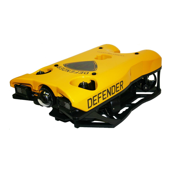
- Page 10 Operator's Manual, 1.00.00 MSS Defender Overview The VideoRay Mission Specialist Series is the world's first ROV to deliver custom purpose-built vehicles using a standard production packaging process. Mission Specialist ROVs are literally built around the payload using core modules instead of figuring out how to adapt an existing vehicle platform in order to mount the payload.
- Page 11 MSS Defender Operator's Manual, 1.00.00 MSS Vehicle Configurations MSS vehicle configurations include: Defender Pro 5 Vehicles are shown approximately to scale.
-
Page 12: Quick Start Instructions
Operator's Manual, 1.00.00 Quick Start Instructions These Quick Start Instructions are streamlined to cover just the essentials of operating your MSS Defender system. They are provided to get you started as quickly as possible, while keeping you and the equipment safe. - Page 13 Keep fingers, hair, loose clothing and other objects away from VideoRay's propellers and other pinch points. Monitor weather and sea conditions and heed any warnings or alerts. Be aware of and follow any legal ordinances or regulations in your area regarding operation of vessels and underwater equipment in the water.
-
Page 14: Pre-Dive Preparations
Conduct a Visual Inspection Assuming this is your first time using the VideoRay, everything should be in proper working order and ready to go, but it is good practice to perform a pre-dive inspection before every dive, even your first. If any problems are noticed, they should be addressed before continuing. - Page 15 2. Check the horizontal thrusters to make sure that the shafts are not bent and the propellers are free to spin and are not fouled, loose or binding on the thruster guards. 3. Check the vertical thruster(s) to make sure the shaft is not bent and the propeller is not fouled or loose or binding on the float block.
- Page 16 If the system does not pass any of the following tests, it should not be used until the problem is identified and corrected. The VideoRay MSS includes two circuit safety components. GFCI (Ground Fault Circuit Interrupter) LIM (Line Insulation Monitor) Testing the Circuit Safety Components Connect the power cord to a suitable power source.
- Page 17 3. Press the GFCI Reset button to restore power and continue the pre-dive steps. When using a power source that includes a GFCI, the VideoRay supplied GFCI is not needed and can be removed from the power cord. Power On and LIM Tests Set the Power switch to the On position.
-
Page 18: Dive Operations
ROV. The ROV is designed to be operated in a near neutrally buoyant configuration, so the last step before launching your VideoRay is to check the buoyancy, and adjust the ballast if necessary. For most operations, the buoyancy is optimal when the top of the float block is even with the water surface and the ROV is level. -
Page 19: Post-Dive Operations
Automated Flight Operations section for more details. Practice Makes Perfect Developing the skills to operate your MSS Defender like an expert may take some time. Practicing on a regular basis is highly recommended. Post-Dive Operations At the conclusion of your dive, retrieve the VideoRay and power down the system by closing VideoRay Balefire software, turning off the ROV power switch, shutting down the computer and then turning off the main power switch.. - Page 20 Proper maintenance of your VideoRay system ensures a long service life and that it will be ready to operate when you are. After each dive, you should visually inspect the system for damage that might have occurred during your operation.
-
Page 21: Power Module Specifications
Open in New Window MSS Defender features and specifications are subject to change without notice. Specifications for the ROV Modules Specifications for the VideoRay M5 Modules are provided on the following pages. Power Module Specifications Depth Rating 2,000 meters (6,500 feet) - Page 22 Dimensions: 18 cm x 13 cm x 4 cm (7.1 inches x 5.1 inches x 1.6 inches) Weight in Air: 1.14 kg (2.5 pounds) Weight in Water: 0.55 kg (1.2 pounds) Connections 8-Pin Male Connector (Tether) 9-Pin Female Connector (Communications) 5-Pin Female Connectors (Thrusters and LEDs) 2X Power Input...
- Page 23 AHRS Module Specifications Depth Rating 2,000 meters (6,500 feet) Mechanical Dimensions: 17.8 cm x 7 cm x 5.4 cm (7.0 inches x 2.75 inches x 2.12 inches) not including cable Weight in Air: 0.55 kg (1.2 pounds) Weight in Water: 0.21 kg (0.46 pounds) Connections 9-Pin Female Connector Power Input...
- Page 24 Communications RS-485 Galvanically Isolated Control Sensor Feedback Input Current Total Input Voltage Internal Temperature Features Direct Drive Brushless Motor Several Mounting Options 90mm Diameter Propeller 3 Blade Propeller with quick connect/release Collet Smooth Start at 120 RPM Instant Reverse No Cogging Very Quiet and Smooth Operation M5 Thruster Module features and specifications are subject to change without notice.
- Page 25 M5 LED Light Module features and specifications are subject to change without notice. Specifications for the ROV Accessories Specifications for the VideoRay MSS Defender accessories can be found on the respective information pages of each accessory. See the Optional Accessories...
- Page 26 Tether Specifications Tether Diameter Units \ Type Negative Neutral Performance 8.51 +/- 0.38 11.18 +/- 0.50 8.18 +/- 0.50 inches 0.335 +/- 0.015 0.440 +/- 0.020 0.322 +/- 0.020 New tether was introduced in 2018. These tethers include a braided Kevlar around the conductors, are slightly different diameter and can be identified by an "FB"...
- Page 27 Conductor pairs 1 & 2, 4 & 6 and 7 & 8 are twisted. Pins 3 and 5 use 2 conductors each for maximizing power transmission and tether flexibility. Tether Buoyancy Performance and Neutral tether includes buoyancy compensating foam that provides near neutral buoyancy in fresh water.
- Page 28 Monitor) protection module in the ROV DC circuit. System components should not be connected to voltage sources higher than their rating. VideoRay Negative, Neutral and PPT tethers are rated to 600 V DC and are safe to use on any system through the MSS 400 V DC.
-
Page 29: Equipment Guide
MSS Defender Operator's Manual, 1.00.00 Equipment Guide Understanding the features and capabilities of the MSS equipment is essential to get the most value out of using the system. The sections within this Equipment Guide provide details about each of the components. - Page 30 Hand Controller Tether...
- Page 31 MSS Defender Operator's Manual, 1.00.00 The MSS ROV consists of modular components (thrusters, lights, cameras, sensors) and a custom frame. Each MSS vehicle is designed to meet the requirements of a specific underwater mission. The frame and sensor payload can be optimized to deliver the vehicle to its intended destination and accomplish the tasks, whether that be recording video, taking measurements of various parameters, or navigation and remote sensing such as sonar or laser imaging.
- Page 32 ROV Orientation and Directions Reference Bow - The front of the ROV. Stern - The rear of the ROV Port - The left side of the ROV when facing forward. Starboard - The right side of the ROV when facing forward. Fore - Towards the front or The forward direction.
-
Page 33: Power Module
Power Module The Power Module receives power from the topside and converts it to power levels required by the various modules, sensors and accessories. 8 Pin Male Tether Connector Function Interlock (GND) Interlock (Sense) Tether V+ M100 EOP+ Tether V- M100 EOP- RS-485 A RS 485 B... -
Page 34: Communications Module
RS-485 B 24 White Power is rated at 750 Watts per port for 1,500 Watts total. 9 Pin Female Communications Module Interface Connector Function 24 V DC + M100 EOP + M100 EOP - RS-485 A RS-485 B 12 V DC + Power is rated at 300 Watts for the 24 Volt circuit and 120 Watts for the 12 Volt circuit. - Page 35 9 Pin Interface Connectors Pin Male Connector (port 1) Female Connectors (ports 2-6) ETH_RXP + ETH_RXP - 24 V DC + 24 V DC + M100 EOP + ETH_TXP + M100 EOP - ETH_TXP - RS-485 A RS-485 A RS-485 B RS-485 B 12 V DC + 12 V DC +...
-
Page 36: Number Assignment
Number Assignment Port Power 7444 (vrport1) 115200 Communications 7444 (vrport1) 115200 Module AHRSD 7445 High Definition Camera 7446 Oculus Sonar 7447 Nortek DVL 7448 Rotating Manipulator, 7449 38400 Defaults: Group ID - 193; Node ID - 2; IP address - 192.168.1.64; RS-485 accessible AHRS Module AHRS - Attitude and Heading Reference System The AHRS is also sometimes referred to as an Inertial Measurement Unit, or IMU. - Page 37 RS-485 B 12 V DC + AHRS Module Arrangement The Defender vehicle AHRSD is mounted in the top center of the ROV frame. AHRSD Group Node Application TCP/IP TCP/IP Port Notes Location Address Number Top Center 192.168.1.65 2 (7446) Port 7444 IMU, Port 7445 Depth Thruster Module MSS vehicles use a modular thruster configuration that allows vehicle designs to be optimized for...
- Page 38 Left-hand propellers can be identified as follows: The top blade has the leading edge on the left when viewed from the end with the nut. The blades appear to curve clockwise when viewed from the end with the nut. Left hand propellers have hub that is all plastic. Cable Pinout The Thruster connector uses a male / female stackable connector allowing the thrusters and LED lights to be connected in series.
-
Page 39: Camera Module
Vertical Forward Right Enable Port Vertical Forward Left Disable Starboard Vertical Aft Left Enable Camera Module The camera module provides a live video feed from the vehicle to the surface. Cable Pinout Function ETH_RXP + ETH_RXP - 24 V DC + ETH_TXP + ETH_TXP - RS-485 A... - Page 40 12 V DC + Camera Arrangement High Definition Camera Camera Location Group ID Node ID TCP/IP Address Notes Forward Center 192.168.1.11 LED Light Module The LED Light Module provides variable levels of illumination and beam pattern control. Cable Pinout The LED Light connector uses a male / female stackable connector allowing the LED lights and thrusters to be connected in series.
-
Page 41: Rov Connections
RS-485 B 24 White Lights Arrangement Light Location Group ID Node ID Application ID Notes Forward Top Port Forward Top Starboard 131 ROV Connections The MSS ROV system uses 3 types of connectors for power and communications between the control panel, vehicle modules and accessories. - Page 42 ETH_TXP + Ground ETH_TXP - RS-485 A RS-485 B 12 V DC + Pin numbering is clockwise starting at 1 in the upper left when looking at the face of the male connector with the row of 5 pins on top. ROV Connections...
- Page 43 User Control Console Power Specifications The VideoRay MSS operates on typical residential power in the range of 100-240 Volts AC, 50,60 Hz. This can be provided from the land-based grid, a generator, or a battery with an inverter (optional). The typical power requirements for operating from a generator or inverter are 3,000 Watts continuous minimum.
-
Page 44: Safety Circuits
You must press the Reset Button to enable it. When enabled, the green LED will be illuminated. When using a power source that includes a GFCI, the VideoRay supplied GFCI is not needed and can be removed from the power cord. -
Page 45: Switches And Connections
The LIM has additional features that are described in more detail in the LIM Module Manual. ROV Power Safety Interlock The ROV Power Safety Interlock prevents the ROV power from being engaged unless an ROV is plugged into the tether. This feature protects users from accidentally contacting the ROV power circuit of an open tether connector. - Page 46 The Display Port cable uses a locking locking connector. Make sure to press the release button when disconnecting the cable to avoid damaging the connector. Computer The computer provides the hardware and operating system platform for VideoRay ROV control software and image and video editing and production. The computer is embedded in the User Control Console.
- Page 47 VideoRay does not recommend installing additional hardware or software on the computer unless you are familiar with its operation and confident it will not interfere with the VideoRay control software or the computer's ports. Software that is packaged with VideoRay accessories has been tested and is approved for use.
- Page 48 Power Input 12 VDC Native Resolution 1920 X 1080 Brightness High Bright � 1000 nits Features Wide Viewing Cone 10 Point PCAP Touch Front Full Range Diming Pot Monitor specifications are subject to change without notice.
-
Page 49: Hand Controller
MSS Defender Operator's Manual, 1.00.00 Hand Controller The hand controller is used to operate the VideoRay and its features. Several types of hand controllers are supported. Controllers not included in your configuration are available from VideoRay for purchase. Supported controllers include:... -
Page 50: Lateral Control
The Joystick does not have a label. Displace the joystick forward (away from you) to move the ROV forward. Displace the joystick rearward (toward you) to move the ROV backward. The greater the displacement from the center position, the faster the ROV will move or turn in that direction. -
Page 51: Depth Control
Do not run the horizontal thrusters in air for an extended period of time. Doing so may cause overheating and damage to the components. Yaw Control The joystick is used to control the yaw motion of the ROV. Location The Joystick does not have a label. Rotate the Joystick to the left to turn (yaw) the ROV to its left. - Page 52 Rotate the Depth Control knob forward (counterclockwise) to dive. The greater the rotation from the center position, the faster it will dive. Rotate the Depth Control knob backward (clockwise) to surface. The greater the rotation from the center position, the faster it will surface. Do not run the vertical thruster in air for an extended period of time.
- Page 53 Pitch Down Press the Pitch Down button to pitch the nose of the vehicle down in 5 degree increments. You can press the Pitch Up button to increase the pitch, or press the Pitch Reset button to return to level. Pitch Down Pitch / Roll Reset The Pitch / Roll Reset button restores the vehicle to a level attitude.
- Page 54 Press the All Autos Off button to disable all active auto modes and dynamic positioning. All Autos OFf Lights Intensity The Lights knob controls the intensity of the lights. Control Location and Labels Lights Intensity Rotate the Lights Intensity knob counter clockwise to dim the Lights and clockwise to increase the intensity of the lights.
- Page 55 Press and hold the Tilt Up button to tilt the front camera up. Release the button when the camera has tilted to the desired setting or has reached the end of its range. You should not continue to hold either tilt button when the camera has reached the end of its tilt range.
- Page 56 Press and hold the Camera Focus In button to adjust the camera focus for near objects. Release the button when the camera has focused to the desired setting or has reached the end of its range. Camera Focus In Camera Focus Out The Camera Focus Out button adjusts the focus of the front camera for far objects.
-
Page 57: Video Record
Press the Snapshot button to capture a still image from the active camera. Snapshots are saved as .JPG formatted files in the gss_logs folder. They are automatically named by date and time. For more information, see the Snapshots section of the Operations Guide. - Page 58 Manipulator Up Press and hold the Manipulator Open button to open the jaws of the manipulator. Release the button when the manipulator jaws open the desired amount or have reached the end of their range. You should not continue to hold the Manipulator Open button when the jaws have reached the end of their range.
- Page 59 Rotate the Manipulator Rotate knob clockwise to rotate the manipulator jaws clockwise (when viewed from the rear of the manipulator). Rotate the Manipulator Rotate knob counterclockwise to rotate the manipulator jaws counterclockwise (when viewed from the rear of the manipulator). Center the Manipulator Rotate knob to stop the manipulator jaws from rotating.
-
Page 60: Sonar Mode
Sonar Mode... - Page 61 Camera/Lights Mode...
- Page 62 Manipulator Mode...
- Page 63 Raw Input...
- Page 65 MSS Defender Operator's Manual, 1.00.00 Tether Tether connects the ROV to the surface and provides power, communications, video and an APIC (Auxiliary Pair of Independent Conductors) for accessory use. The tether consists of conductors, a ® Kevlar strength member, flotation (for Neutral and Performance tethers) and an outer jacket. It is available three types: Negative, Neutral and Performance (often called PPT), and can be purchased in standard and custom lengths.
- Page 66 Tether connectors should not be lubricated with petroleum products or grease. Petroleum will degrade the rubber and grease will attract dirt and lead to abrasion and corrosion. VideoRay recommends lubricating the tether connectors with pure silicone spray.
- Page 67 Interlock (Sense) 24 400 VDC + 16 (x2) 20 (x2) 24 (x2) M100 EOP+ Ground 16 (x2) 20 (x2) 24 (x2) M100 EOP- RS-485 A RS-485 B All conductors are straight through, such that pin 1 in the male connector is connected to socket 1 in the female connector, and so on for all eight pins / sockets.
- Page 68 1. Insert the loop end of the tether webbing into the loop end of the strain relief cable. 2. Pass the eye socket end of the strain relief cable through the loop end of the tether webbing. 3. Pull the eye socket end of the strain relief cable to secure the connection. 4.
- Page 69 5. Insert the strain relief eye socket into the hole in the frame and secure it with the retaining screw. 6. Make sure the connection is secure and that all of the load is carried by the strain relief and there is no load on the tether connection.
- Page 70 1. Ensure that you have all three parts of the tether to tether strain relief as shown below. 2. Ensure that both carabiners are labeled with '600lbs'. Older models of VideoRay ROVs used the '450lbs' rated carabiners and these should not be used with MSS systems.
- Page 71 Using the incorrect carabiners may cause the strain relief to fail under loading. 3. Connect one of the carabiners to one loop end of the tether to tether strain relief cord.
- Page 72 4. Connect the carabiner to the tether strain relief webbing and secure the carabiner locking nut. 5. Repeat steps 3 and 4 using the second carabiner and strain relief webbing from the second tether.
- Page 73 6. Make sure the strain relief cable connections are secure so that all of the load is carried by the strain relief and there is no load on the tether connection. When working in an area where there is a chance the tether can become snagged on a protruding object, the connection can be wrapped with tape to prevent a protruding object from passing through the space between the tether and the strain relief cable.
-
Page 74: Connections Summary
MSS Defender Operator's Manual, 1.00.00 Connections Summary The following connections are required: 1. Connect the female end of the tether to the ROV. 2. Secure the tether strain relief to the ROV. 3. Connect the male end of the tether to the User Control Console. -
Page 75: Included Accessories
Optional Accessories The following pages provide information about the various accessories that are supported on the VideoRay Defender. Your configuration may or may not include all of these accessories. Sonar The sonar provides the operator with a forward-looking image of the ROV's surrounding environment even when visibility is limited. -
Page 76: Reference Documents
- anything from untangling tether snags to collecting samples to recovering objects up to 22.6 kg (50 lb). Using the hand controller, you can retrieve items in confined or hazardous locations. The VideoRay ROV's camera can be tilted down to focus on the jaw to provide a close view of the operation. - Page 77 Reference Documents Inuktun Rotating Manipulator Jaws Specifications Videoray Rotating Manipulator Operator's Manual Manufacturer's User Manual The DVL (Doppler Velocity Log) is an acoustic device that calculates the vehicle velocity vector by measuring the Doppler shift of its array of four transducers. When combined with the compass, the ROV's direction and position can be also calculated.
- Page 78 VideoRay ROV GPS The VideoRay ROV GPS is mounted on the vehicle and can be used to establish the location of the vehicle when it is on the surface. This can be used to "seed" the navigation system with coordinates.
- Page 79 Reference Documents VideoRay GPS Antenna Manual VideoRay GPS Receiver Manual GlobalSat GlobalSat GlobalSat USB 5 Hz BU-353-S4-5Hz is a WAAS enabled USB GPS receiver that features a highly sensitive, low power consumption chipset in a ultra compact form factor. The BU-353-S4-5Hz is powered by a SiRF Star IV GPS chipset, and will provide you with superior performance in urban canyons, and in dense foliage.
- Page 80 Reference Documents GlobalSat USB 5 Hz Data Sheet Lowrance Lowrance Lowrance Point 1 The Lowrance Point-1 is the ideal position and heading device. The Point-1 provides extremely accurate and rapid boat position and speed updates. In addition - unlike other position-only antennas - the Point-1 provides heading for accurate boat direction at any speed and for radar/chart overlay.
- Page 81 The USBL system uses acoustic beacons on the surface and ROV to provide a relative location of the ROV with respect to the surface beacon. This location is described by bearing and distance. GPS can be used to convert this relative location into a precise latitude and longitude. Blueprint Subsea BluePrint Subsea SeaTrac...
- Page 82 Supplemental spare parts for field repairs (Basic spares are included for some items) Tactical Operations Support Tether weights and davit Retrieval devices or baskets In general, VideoRay does not supply these items, and users must procure them on their own.
-
Page 83: Software Guide
3. Module Firmware installed on each module to allow the module to perform its functions. The topside user interface software is available in several versions: 1. Greensea Systems Inc., with fully autonomous capabilities 2. VideoRay basic interface 3. User developed software... - Page 84 Greensea Systems Interface Overview Greensea's EOD Workspace is the topside control software for the MSS. To start VideoRay EOD Workspace, double click on the Defender icon on the desktop. For more information about Greensea's VideoRay EOD Workspace software, see the Greensea Section MSS Manuals Compilation.
- Page 85 MSS Defender Operator's Manual, 1.00.00 VideoRay Interface Overview There are four applications that are required to operate the VideoRay vehicle control software. These are stored in the ~/Flighthack folder. Start the thruster controls using vr_engage.py Start the camera controls using vr_engage_camera.py Start the video window Video is automatically in record mode when the video window is started.
-
Page 86: Software Management
7. In the Terminal Window, enter the following commands a. cd .config/greensea_systems b. rm workspace.ini (Do not delete any other files, specifically gss.key) 8. Close the Terminal Windows The new version should be installed and ready to run. Contact VideoRay support if you need assistance. -
Page 88: Module Configuration
MSS Defender Operator's Manual, 1.00.00 Module Configuration The modular concept requires that modules be configured prior to installation or replacement in a specific vehicle arrangement. Configuration information is specific to each vehicle. Information about the configuration for a specific vehicle can be found in the... -
Page 89: Updating Firmware
Command: vr_refresh The vr_refresh command is used to update the firmware on a module. vr_Refresh [OPTIONS] [SINGLE_HEX_FILE_NAME] [Options] - See the table below [SINGLE_HEX_FILE_NAME] - The file name of the firmware update, including its path. OPTION Alternate Argument(s) Description Default --help Display this help information --version... - Page 90 Camera Module vr_refresh -c vrport3 -i 4 ~/firmware/camera_adapter-X.Y.Z.hex --block_size 16384 LED Module (Use the correct Node ID) vr_refresh -i 11 ~/firmware/led_controller-X.Y.Z.hex Firmware Block Sizes Module Block Size Comms Path Power Module 16384 Direct Communications Module 16384 Direct AHRS Module 16384 vport2 Power Module Default...
- Page 91 vr_enum -c vrport2 Camera Module vr_enum -c vrport3 Some of the options use two dashes "--," not a long dash Command: vr_setid The vr_setid command is used to set the Node_ID and Group_ID of a module. vr_setid [OPTIONS] SN Node_ID Group_ID SN - See the table below Node_ID - The Node ID to program into the module (1 - 255) Group_ID - The Group ID to program into the module (1 - 255)
- Page 92 Some of the options use two dashes "--," not a long dash Command: vr_debug_putty.py The vr_debug_putty.py command is used to configure or test a module. ./vr_debug_putty.py [OPTIONS] [N [N...]] [Options] - See the table below N - The Node ID of the module to reset and enter debug mode. This command must be executed from the flighthack folder and requires the preceding "./"...
- Page 93 ./vr_create_virtport_all.sh & There are no arguments for this command. This command must be executed from the flighthack directory and requires the preceding "./" The trailing "&" allows this command to run in the background, otherwise you would need to open a new terminal window to use commands that access the virtual ports.
- Page 94 Users may check this list against chemical compatibility charts available from several sources. This information is provided for convenience. Providing this information does not explicitly or implicitly extend the warranty to cover the use of VideoRay products in solutions that are not specifically listed in Environmental Compatibility section.
-
Page 95: Project Management
MSS Defender Operator's Manual, 1.00.00 Project Management While the differences between conducting a recreational dive, an inspection of an offshore well riser, and a drowning victim recovery are quite dramatic, each of these dive missions usually consist of the following phases: 1. - Page 96 MSS Defender Operator's Manual, 1.00.00 Maintenance Guide This section will describe the maintenance requirements and procedures for periodic or common maintenance requirements. It will not be detailed enough to be considered a component level repair manual, but will address component replacement of modular components.
- Page 97 VideoRay MUST be returned to a VideoRay Authorized Service Center for service and repair. VideoRay also understands that logistics and other issues may make it difficult and costly to return the equipment to a Factory Authorized Service Center for completion of some of the simpler procedures.
-
Page 98: Configuration / Calibration
Magnetic Field Mapper software must be installed on the Operator Control Console. If the Magnetic Field Mapper software is not installed, It can be downloaded at: https://videoray.exavault.com/files/quarterdeck/xsens/mag_mapper.tgz. The user name is quarterdeck and the password is quarterdeck (use all lower case). After logging in, navigate to the xsens/ folder and download mag_mapper.tgz. - Page 99 7. When asked if you trust this application and want to Launch it, click on the Yes button. 8. When asked for the password, enter videoray and click on the Authenticate button (use all lower case). 9. When the Magnetic Field Mapper software starts, make sure the Use Motion Tracker option selected and click on the Next and then the Scan buttons.
- Page 100 12. The Capturing Data screen will appear with a graphic display of three axes and a sphere. 13. The vehicle must be rotated slowly 360 degrees about all axes. As you rotate, the sphere will update with areas that are mapped. The goal is to cover as much of the sphere as possible. a.
- Page 101 15. The display will update with a before (red) and after (blue) graph. The red graph will likely have sections with a lot of variation and be offset from 1.0. The blue graph should have much less variation and average value close to 1.0. 16.
-
Page 102: Power Module Replacement
MSS Defender Operator's Manual, 1.00.00 Module Configuration and Replacement Power Module Replacement Replacing a Power Module requires hardware replacement. Currently, the Power Module will be pre- configured when delivered, so there is no need for software configuration procedures. Hardware Replacement To remove and replace a Power Module, follow these steps: 1. - Page 103 2. Remove the top float block by removing the four screws holding the float block to the frame. 3. The DVL will need to be removed in order to remove the Communications Module. 4. Remove the Communications Module male connector cable from the front of the Power Module. 5.
- Page 104 You do not need to type the Enter key. In configuration mode you are now able to configure the baud rate for the rotating manipulator port. 8. Using the values from the Communications Module configuration table change the parameters on the Communications Module to match the baud rate for the manipulator port from the table. To change the baud rate value for the manipulator port, follow these steps: 1.
- Page 105 Hardware Replacement To remove and replace a thruster, follow these steps: 1. Power down the system. 2. Remove the top float block by removing the four screws holding the float block to the frame. 3. Note the position of the thruster being replaced in the vehicle frame. The position of the thruster being replaced will determine the propeller orientation and configuration parameters to be programmed into the replacement.
-
Page 106: Camera Replacement
where SN is the serial number of the replacement thruster (case sensitive value as found in the vr_enum output), and the NodeID and GroupID are from the thruster configuration table This step ensures that each thruster has a unique Node ID on this vehicle. 7. -
Page 107: Led Light Replacement
4. Carefully thread the disconnected cable and connector back through the frame until it is clear. 5. Using a Phillips head screw driver, loosen the 4 screws (2 in each bracket) that hold the Camera to the frame. 6. Slide the camera out of the brackets from the front of the vehicle. 7. - Page 108 Refer to the configuration parameter table in the LED Light section of the Equipment Guide.: Commands below are case sensitive. 1. Connect and power up the system, but do not start the control software. 2. Launch the terminal program and use the following commands to program the LED Light. 3.
Need help?
Do you have a question about the MSS Defender and is the answer not in the manual?
Questions and answers