Table of Contents
Advertisement
SPLIT-TYPE, HEAT PUMP AIR CONDITIONERS
TECHNICAL & SERVICE MANUAL
Series PCFY
<Indoor unit>
[Model name]
PCFY-P40VGM-E
PCFY-P63VGM-E
PCFY-P100VGM-E
PCFY-P125VGM-E
INDOOR UNIT
Ceiling Suspended
[Service Ref.]
PCFY-P40VGM-E
PCFY-P63VGM-E
PCFY-P100VGM-E
PCFY-P125VGM-E
REVISED EDITION-A
R410A
R407C
Revision:
• RoHS PARTS LIST is added.
• Some descriptions have
been modified.
• Please void OC308.
Note:
• This manual describes only
service data of the indoor
units.
• RoHS compliant products
have <G> mark on the spec
name plate.
• For servicing of RoHS com-
pliant products, refer to the
RoHS Parts List.
CONTENTS
1. SAFETY PRECAUTION ······················2
2. PART NAMES AND FUNCTIONS ·······6
3. SPECIFICATIONS ·······························8
4. OUTLINES AND DIMENSIONS·········11
5. WIRING DIAGRAM····························15
8. DISASSEMBLY PROCEDURE··········24
9. PARTS LIST·······································28
10. RoHS PARTS LIST···························35
11. OPTIONAL PARTS ··························42
July 2006
No. OC308
R22
Advertisement
Table of Contents

Related Manuals for Mitsubishi Electric PCFY-P40VGM-E


Summary of Contents for Mitsubishi Electric PCFY-P40VGM-E
-
Page 1: Table Of Contents
TECHNICAL & SERVICE MANUAL Ceiling Suspended Series PCFY R410A R407C <Indoor unit> Revision: [Model name] [Service Ref.] • RoHS PARTS LIST is added. PCFY-P40VGM-E • Some descriptions have PCFY-P40VGM-E been modified. PCFY-P63VGM-E PCFY-P63VGM-E • Please void OC308. PCFY-P100VGM-E Note: PCFY-P100VGM-E •... -
Page 2: Safety Precaution
SAFETY PRECAUTION CAUTIONS RELATED TO NEW REFRIGERANT Cautions for units utilizing refrigerant R407C Do not use the existing refrigerant piping. Use liquid refrigerant to seal the system. The old refrigerant and lubricant in the existing piping If gas refrigerant is used to seal the system, the composition contains a large amount of chlorine which may cause the of the refrigerant in the cylinder will change and performance lubricant deterioration of the new unit. - Page 3 [3] Service tools Use the below service tools as exclusive tools for R407C refrigerant. Tool name Specifications Gauge manifold ·Only for R407C. ·Use the existing fitting SPECIFICATIONS. (UNF7/16) ·Use high-tension side pressure of 3.43MPa·G or over. Charge hose ·Only for R407C. ·Use pressure performance of 5.10MPa·G or over.
- Page 4 Cautions for units utilizing refrigerant R410A Use a vacuum pump with a reverse flow check Do not use the existing refrigerant piping. valve. The old refrigerant and lubricant in the existing piping Vacuum pump oil may flow back into refrigerant cycle and contains a large amount of chlorine which may cause the that can cause deterioration of refrigerant oil etc.
- Page 5 [1] Cautions for service (1) Perform service after collecting the refrigerant left in unit completely. (2) Do not release refrigerant in the air. (3) After completing service, charge the cycle with specified amount of refrigerant. (4) When performing service, install a filter drier simultaneously. Be sure to use a filter drier for new refrigerant.
-
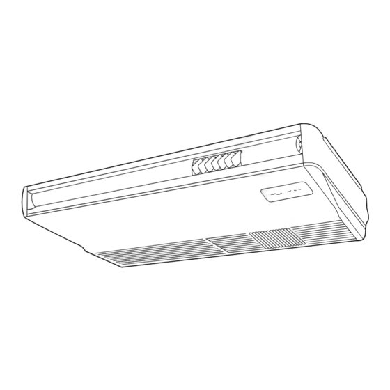
Page 6: Part Names And Functions
PART NAMES AND FUNCTIONS Indoor Unit Left/right guide vanes Change the direction of airflow from the horizontal blower. Air outlet Long-life fillter Removes dust and foreigh matter from air coming in through the grille (Recommended cleaning interval : Approx, every 2,500 operating hours) Air intake Up/down guide vanes Intake grille... - Page 7 Display “Sensor” indication Displayed when the remote controller sensor is used. Day-of-Week For purposes of this explanation, Shows the current day of the week. all parts of the display are shown as lit. During actual operation, only Time/Timer Display the relevant items will be lit. “Locked”...
-
Page 8: Specifications
SPECIFICATIONS 3-1. SPECIFICATIONS Item PCFY-P40VGM-E PCFY-P63VGM-E PCFY-P100VGM-E PCFY-P125VGM-E · Power Single phase 220-230-240V 50Hz / 220V 60Hz Cooling capacity 11.2 14.0 Heating capacity 12.5 16.0 Cooling 0.10 0.13 0.16 0.24 Input Heating 0.10 0.13 0.16 0.24 Cooling 0.46 0.60 0.73 1.10... - Page 9 3-2. ELECTRICAL PARTS SPECIFICATIONS Model Symbol PCFY-P40VGM-E PCFY-P63VGM-E PCFY-P100VGM-E PCFY-P125VGM-E Parts name Room temperature TH21 Resistance 0:/15k", 10:/9.6k", 20:/6.3k", 25:/5.4k", 30:/4.3k", 40:/3.0k" thermistor Liquid pipe temperature TH22 Resistance 0:/15k", 10:/9.6k", 20:/6.3k", 25:/5.4k", 30:/4.3k", 40:/3.0k" thermistor Gas pipe temperature TH23 Resistance 0:/15k", 10:/9.6k", 20:/6.3k", 25:/5.4k", 30:/4.3k", 40:/3.0k"...
-
Page 10: Noise Criterion Curves
3-3. NOISE CRITERION CURVES CEILING UNIT About 1.4m MICROPHONE PCFY-P40VGM-E PCFY-P63VGM-E SPL(dB) LINE SPL(dB) LINE NOTCH NOTCH NC-70 NC-70 NC-60 NC-60 NC-50 NC-50 NC-40 NC-40 NC-30 NC-30 APPROXIMATE THRESHOLD OF HEARING FOR NC-20 NC-20 CONTINUOUS APPROXIMATE THRESHOLD OF HEARING NOISE... -
Page 11: Outlines And Dimensions
OUTLINES AND DIMENSIONS Unit : mm INDOOR UNIT PCFY-P40VGM-E... - Page 12 PCFY-P63VGM-E Unit : mm...
- Page 13 PCFY-P100VGM-E Unit : mm...
- Page 14 PCFY-P125VGM-E Unit : mm...
-
Page 15: Wiring Diagram
WIRING DIAGRAM PCFY-P40VGM-E PCFY-P63VGM-E PCFY-P100VGM-E PCFY-P125VGM-E Legend Symbol Name Symbol Name Symbol Name Indoor controller board Capacitor(fan motor) Circuit board Address Linear expansion valve Switch Mode selection CN32 Connector Remote switch CN51 Fan motor(with inner thermo) Voltage selection Centrally control... -
Page 16: Refrigerant System Diagram
REFRIGERANT SYSTEM DIAGRAM PCFY-P40VGM-E PCFY-P63VGM-E PCFY-P100VGM-E PCFY-P125VGM-E Strainer (#50mesh) Gas pipe temperature thermistor TH23 Gas pipe Liquid pipe temperature thermistor TH22 Flare connection Liquid pipe Heat exchanger Linear expansion valve Strainer (#100mesh) Strainer (#100mesh) Room temperature thermistor TH21 Capacity PCFY-P100VGM-E... - Page 17 TROUBLE SHOOTING 7-1. How to check the parts PCFY-P40VGM-E PCFY-P63VGM-E PCFY-P100VGM-E PCFY-P125VGM-E Parts name Check points Room temperature Disconnect the connector then measure the resistance using a tester. thermistor (TH21) (Surrounding temperature 10:~30:) Liquid pipe temperature Normal Abnormal thermistor (TH22) Refer to the next page for the details.
- Page 18 <Thermistor Characteristic graph> < Thermistor at lower temperature > Room temperature thermistor(TH21) Thermistor at Liquid pipe temperature thermistor(TH22) lower temperature Gas pipe temperature thermistor(TH23) Thermistor R =15k' ± 3% Fixed number of B=3480K ± 2% Rt=15exp { 3480( 273+t 15k' 9.6k' 6.3k' 5.4k'...
- Page 19 <Output pulse signal and the valve operation> Closing a valve : 1 Output Output Opening a valve : 4 (Phase) number The output pulse shift as above order. 1. When linear expansion valve operation stops, all output phase become OFF. 2.
- Page 20 7-2. FUNCTION OF DIP SWITCH PCFY-P40VGM-E PCFY-P63VGM-E PCFY-P100VGM-E PCFY-P125VGM-E Operation by switch Switch Pole Function Remarks Room temperature Thermistor Indoor unit Built-in remote controller Address board position Filter clogging detection Provided Not provided <At delivery> Filter cleaning sign 2500hr 100hr...
- Page 21 Switch Operation by switch Remarks Address board Ceiling height can be changed depends on SW A setting. (High) <At delivery> Set the ceiling (Standard) height (Low) Address board When the optional high performance filter ele- <At delivery> ments (filter casement) is attached to the unit, Option Option be sure to set switch to the option side in...
- Page 22 7-3. TEST POINT DIAGRAM 7-3-1. Indoor controller board PCFY-P40VGM-E PCFY-P63VGM-E PCFY-P100VGM-E PCFY-P125VGM-E CN29 Pipe temperature CN2D CN2M CN3A thermistor/Gas (TH23) Connect to the indoor Connect to the terminal block (TB5) Connect to the terminal block (TB15) power board (CN2S) (M-NET transmission connecting wire) (MA-Remote controller connecting wire) 12.5-13.7V DC (Pin1 1 (+))
- Page 23 7-3-2. Indoor power board PCFY-P40VGM-E PCFY-P63VGM-E PCFY-P100VGM-E PCFY-P125VGM-E CN2S Connect to the indoor power board (CN2D) Between 1 1 to 3 3 12.6-13.7V DC (Pin1 1 (+)) CNSK Connect to the indoor controller board (CNDK) Between 1 1 to 3 3 220-240V AC...
-
Page 24: Disassembly Procedure
DISASSEMBLY PROCEDURE PCFY-P40VGM-E PCFY-P63VGM-E PCFY-P100VGM-E PCFY-P125VGM-E OPERATING PROCEDURE PHOTOS & ILLUSTRATIONS 1. Removing the air intake grille Figure 1 (1) Slide the intake grille holding the knobs at backward to open the intake grille. (2) When the intake grille left open, push the stoppers on the rear hinges (at two locations) to pull out the intake grille. - Page 25 OPERATING PROCEDURE PHOTOS & ILLUSTRATIONS 3. Removing the fan motor Photo 2 (1) Remove the air intake grille. (2) Disconnect the fan motor guard. Screws Motor guard (3) Unscrew screws for removing the motor guard. Motor (4) Unscrew screws for removing the fan guard. Set screw (5) Remove the screw for removing the motor support at both left and right side.
- Page 26 OPERATING PROCEDURE PHOTOS & ILLUSTRATIONS 6. Removing the vane motor Photo 4 (1) Remove the air intake. Screws (2) Remove the left side panel. Relay connector of (3) Remove the relay connector of vane motor. the vane motor (4) Remove the electrical box. (5) Remove the screws of vane motor, then remove vane motor.
- Page 27 OPERATING PROCEDURE PHOTOS & ILLUSTRATIONS 9. Removing the drain pan Photo 8 (1) Remove the air intake grille. (2) Remove the beam. (3) Remove the side panel (right and left). (4) Remove the under panel. Remove the screws of the right and left side drain pan.
-
Page 28: Parts List
PARTS LIST (non-RoHS compliant) ELECTRICAL PARTS PCFY-P40VGM-E PCFY-P63VGM-E PCFY-P100VGM-E PCFY-P125VGM-E TEMP. ON/OFF Q'ty/set Price Wiring Recom- Remarks PCFY- • VGM-E Parts No. Parts Name Diagram Specifications mended (Drawing No.) Unit Amount Symbol Q'ty P63 P100 P125 R01 30L 255 CAPACITOR... - Page 29 STRUCTURAL PART PCFY-P40VGM-E 11 12 Part number that is circled is not shown in the figure. Q'ty/set Price Recom- Wiring Remarks mended Parts No. Parts Name Specifications Diagram PCFY- (Drawing No.) Unit Amount Symbol Q'ty P40VGM-E R01 57N 666 S.PLATE-L R01 A15 500 L.L FILTER...
- Page 30 STRUCTURAL PART PCFY-P63VGM-E PCFY-P100VGM-E 11 12 13 Part number that is circled is not show in the figure. Q'ty/set Price Wiring Recom- Remarks Parts No. Parts Name Diagram Specifications PCFY- • VGM-E mended (Drawing No.) Unit Amount Symbol Q'ty P100 R01 17J 662 LEFT SIDE PANEL R01 35J 662...
- Page 31 STRUCTURAL PART PCFY-P125VGM-E Part number that is circled is not shown in the figure. Q'ty/set Price Wiring Recom- Remarks Parts No. Specifications Diagram mended Parts Name PCFY- (Drawing No.) Unit Amount Symbol Q'ty P125VGM-E R01 35J 662 LEFT SIDE PANEL R01 35J 666 S.PLATE-L R01 A17 676...
- Page 32 FAN AND HEATER PARTS PCFY-P40VGM-E Part number that is circled is not shown in the figure. Wiring Recom- Q'ty/set Price Remarks Diagram Parts No. mended Parts Name Specifications PCFY- (Drawing No.) Amount Unit P40VGM-E Symbol Q'ty R01 17J 130 MOTOR LEG...
- Page 33 FAN AND HEATER PARTS PCFY-P63VGM-E PCFY-P100VGM-E Part number that is circled is not shown in the figure. Q'ty/set Wiring Recom- Price Remarks Parts Name Specifications Parts No. PCFY- • VGM-E Diagram mended (Drawing No.) Unit Amount P100 Symbol Q'ty R01 29J 130 MOTOR LEG R01 35J 130 MOTOR LEG...
- Page 34 FAN AND HEATER PARTS PCFY-P125VGM-E 17·18 Part number that is circled is not shown in the figure. Q'ty/set Price Wiring Recom- Remarks Diagram mended Parts No. Specifications PCFY- Parts Name (Drawing No.) Unit Amount Symbol Q'ty P125VGM-E SHAFT R01 29J 100 R01 41J 130 MOTOR LEG R01 43E 126...
-
Page 35: Rohs Parts List
RoHS PARTS LIST ELECTRICAL PARTS PCFY-P40VGM-E PCFY-P63VGM-E PCFY-P100VGM-E PCFY-P125VGM-E TEMP. ON/OFF Q'ty/set Price Wiring Recom- Remarks Parts No. Parts Name PCFY- • VGM-E Diagram mended Specifications (Drawing No.) Unit Amount Symbol Q'ty P125 P63 P100 R01 A15 255 440V CAPACITOR... - Page 36 STRUCTURAL PART PCFY-P40VGM-E 11 12 Part number that is circled is not shown in the figure. Q'ty/set Price Wiring Recom- Remarks mended Parts No. Parts Name Specifications PCFY- Diagram (Drawing No.) Unit Amount Q'ty Symbol P40VGM-E R01 E00 666 S.PLATE-L R01 A30 500 L.L FILTER...
- Page 37 STRUCTURAL PART PCFY-P63VGM-E PCFY-P100VGM-E 11 12 13 Part number that is circled is not show in the figure. Q'ty/set Price Wiring Recom- Remarks Diagram Parts No. Parts Name Specifications mended PCFY- • VGM-E (Drawing No.) Unit Amount Symbol Q'ty P100 R01 18J 662 LEFT SIDE PANEL R01 36J 662...
- Page 38 STRUCTURAL PART PCFY-P125VGM-E Part number that is circled is not shown in the figure. Q'ty/set Price Wiring Recom- Remarks Parts No. Specifications Parts Name Diagram mended PCFY- (Drawing No.) Unit Amount Symbol Q'ty P125VGM-E R01 36J 662 LEFT SIDE PANEL R01 E01 666 S.PLATE-L R01 A19 676...
- Page 39 FAN AND HEATER PARTS PCFY-P40VGM-E Part number that is circled is not shown in the figure. Wiring Recom- Q'ty/set Price Remarks Diagram Parts No. mended Parts Name Specifications PCFY- (Drawing No.) Amount Unit P40VGM-E Symbol Q'ty R01 31J 130 MOTOR LEG...
- Page 40 FAN AND HEATER PARTS PCFY-P63VGM-E PCFY-P100VGM-E Part number that is circled is not shown in the figure. Q'ty/set Wiring Recom- Price Remarks Parts Name Specifications Parts No. Diagram mended PCFY- • VGM-E (Drawing No.) Unit Amount P100 Symbol Q'ty R01 30J 130 MOTOR LEG R01 32J 130 MOTOR LEG...
- Page 41 FAN AND HEATER PARTS PCFY-P125VGM-E 17·18 Part number that is circled is not shown in the figure. Q'ty/set Price Wiring Recom- Remarks Diagram Parts No. Specifications mended PCFY- Parts Name (Drawing No.) Unit Amount Symbol Q'ty P125VGM-E R01 30J 100 SHAFT R01 33J 130 MOTOR LEG...
-
Page 42: Optional Parts
OPTIONAL PARTS 11-1. DRAIN-UP MACHINE PAC-SE84DMA-E PAC-SE86DMA-E Part No. PAC-SE85DMA-E PCFY-P100VGM-E Applied Service Ref. PCFY-P40VGM-E PCFY-P63VGM-E PCFY-P125VGM-E 11-2. HIGH EFFICIENCY FILTER Part No. PAC-SE80KF-E PAC-SE81KF-E PAC-SE82KF-E PCFY-P63VGM-E Applied Service Ref. PCFY-P40VGM-E PCFY-P125VGM-E PCFY-P100VGM-E... - Page 44 HEAD OFFICE : TOKYO BLDG., 2-7-3, MARUNOUCHI, CHIYODA-KU, TOKYO100-8310, JAPAN cCopyright 2004 MITSUBISHI ELECTRIC ENGINEERING CO., LTD. Distributed in Jul. 2006 No. OC308 REVISED EDITION-A PDF8 Distributed in Apr. 2004 No. OC308 PDF 9 New publication, effective Jul. 2006 Specifications subject to change without notice...
Need help?
Do you have a question about the PCFY-P40VGM-E and is the answer not in the manual?
Questions and answers