
Related Manuals for AeroWorks 150cc Extra 300 ARF-QB


Summary of Contents for AeroWorks 150cc Extra 300 ARF-QB
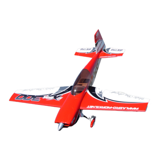
- Page 1 150cc Extra 300 ARF-QB (Quick Build) ASSEMBLY MANUAL AEROWORKS 4903 Nome St– Denver, CO. 80239 www.aero-works.net...
-
Page 2: Table Of Contents
TABLE OF CONTENTS Page Aeroworks Contact Information …………………………………………………………………………. 3 Introduction / Warranty…………………………………………………………………………. ………. 4 Kit Contents………………………………………………………………………………………………… 5 Items Needed To Complete ……………………………………………………………………………….. 8 Tightening and Re-shrinking The Covering ……………………………………………………………… 9 Ultracote™ Colors………………………………………………………………………………………… 10 Checking Seams and Color Overlaps for Good Seal / Sealing Hinge Gaps ………..………………….. 11 Checking Glue Joints …………………………………………..………………………………………….. -
Page 3: Aeroworks Contact Information
Further, Aeroworks reserves the right to change or modify this limited warranty without notice. In that Aeroworks has no control over the final assembly or materials used for final as- sembly, No liability shall be assumed nor accepted for any damage resulting from the use by the user of the final user-assembled product. -
Page 4: Introduction / Warranty
CAD design, laser cut technology and jig-built assures accuracy in all stages of production. The 150cc Extra 300 ARF-QB is designed for gas engines in the 150cc category. The DA- 170cc engine is shown in the assembly instructions. The aircraft was tested with the DA- 170cc and has outstanding performance. -
Page 5: Kit Contents
KIT CONTENTS (2) 3 flat washers 150cc Extra 300 (1) Bottom Hatch for canister pre-installed by (6) 4- BASIC AIRCRAFT PARTS: 40x10mm Hex style Bolts and (6) 3 flat washers (2) L aluminum, 1 left and 1 right installed by M4x20mm Hex bolts and M4 locks and 4mm flat Fuselage with pre-installed vertical fin –... - Page 6 (1) 40mm o.d.x 48 7/8” carbon Tube for wing joint Right Wing with Aileron – covered: Pre-drilled for the (2) 16mm o.d. carbon Tubes for stab joint – one front mounting of the control horns 8 11/16” and one rear 18 1/8” (2) 8-32 blind nuts installed for the wing mounting.
- Page 7 #10: (4) Wooden servo mounting tray for throttle and choke servos (2) Engine mounting template (DA150/170 and Universal) (1) Plywood Stand off for DA150/170 (2) 80mm I.D. hole - MTWTD110 Canister brackets with (4) 4-40x10mm hex head bolts and (4) #3 flat washers (2)70mm I.D.
-
Page 8: Items Needed To Complete
ITEMS NEEDED TO COMPLETE Hardware: • Allen wrenches US and Metric. • Dremel cutting disc and sanding drum tool • Electric drill and selection of bits • Flat head screwdriver • Hobby heat gun • Hobby iron with protective sock •... -
Page 9: Tightening And Re-Shrinking The Covering
TIGHTENING AND RE-SHRINKING THE COVERING 1. Open your kit slowly and take care not to dam- 3. If bubbles persist, use a small pin to punch holes age any parts of the kit. Remove all parts from in the bubble to relieve trapped air and reheat. their plastic protective covers for inspection. -
Page 10: Ultracote™ Colors
Ultracote™ Colors 1. Your model is covered with Ultracote™ covering. In case of repairs, the colors are: Yellow/Silver/Blue Scheme Pearl Blue #845 Silver #881 Cub Yellow #884 White #870 Red/White/Black Scheme Black #874 Silver #881 True Red #866 White #870... -
Page 11: Checking Seams And Color Overlaps For Good Seal Sealing Hinge Gaps
It is the responsibility of the purchaser / operator to check the covering seams and overlaps for security and a good seal. Aeroworks is not responsible for failure of covering seams or overlaps during flight. Note: If covering continues to lift apply a small amount of thin CA underneath the covering. -
Page 12: Checking Glue Joints
CHECKING GLUE JOINTS 1. Go over all seams and glue joints with thin CA, this will ensure your model lasts for many sea- sons to come. Note: Even if you can visibly see glue on all glue joints it is still recommended that the joints be reglued. -
Page 13: Wing Assembly
Note: (2) 6” extension will also be needed per wing when connecting aileron servos to re- ceiver. 3. Attach the 36” extension to the outboard servo lead and secure with an Aeroworks safety clip. Ensure the connectors will not come apart from vibration or light tension. - Page 14 Attach the 12” Extension to the inboard servo 4. Remove the balsa stick with the pull string from lead and secure with an Aeroworks safety the servo well and tie the pull string to the servo clip. Ensure the connectors will not come lead as shown.
- Page 15 Finished servo installation shown below. Assemble two pushrod and control horn assemblies as shown. The ball link goes between the left and right sides of the control horn sides and is secured with a nylon lock nut. IMPORTANT: The ball link for the root end control horn goes in the bottom hole of the horn.
- Page 16 4. Align the control horns over the factory drilled 6. Align the left and right sides of the control horns holes. to the mounting holes and secure using six wood screws as shown. Note: Control horns have been set at a slight offset to allow for maximum torque at full deflection.
- Page 17 Plug the servos into the receiver and turn on. Ensure servos are centered and the servo arms are parallel to the aileron hinge line. Adjust the length of the pushrods so that the aileron is at the neutral position when the servo arms are parallel to the aileron hinge line.
-
Page 18: Stab And Elevator Assembly
4 - Servo Mounting Screws (Micro Fastener Part number STW0209 recommended) ◊ 1 - 48” servo extension ◊ 1 - Aeroworks Safety Clips Note: 48” servo extension will be used to connect servos to receiver during a later step. 4. Install servo with servo mounting screws. - Page 19 Elevator Control Linkage Installation 3. Correct installation of ball link, flat washer and brass spacer to servo arm shown below. 1. Gather the following items for installing the ele- vator linkage: ◊ 1 - 2 1/2” pushrod ◊ 2 - 4-40 ball link assemblies ◊...
- Page 20 7. Plug the 48” Extension into the female end of to lock screws in place. the servo. Secure the servo connectors with an Aeroworks Safety Clip Ensure the connectors Note: CA glues have a fast drying time. will not come apart from vibration or light ten- Remember to work quickly.
-
Page 21: Rudder And Rudder Servos Installation
RUDDER AND RUDDER SERVOS INSTALLATION Mix epoxy in mixing cup and use a tapered Rudder Installation stick to apply the epoxy inside the pre-drilled holes in the trailing edge of the fin. Apply Gather the rudder, hinges, epoxy, Vaseline, epoxy to one side of each hinge and insert the stir sticks, mixing cup and alcohol as shown. - Page 22 Mix epoxy in mixing cup and use a tapered Ensure there is minimal to no gap between fin stick to apply the epoxy inside the pre-drilled and rudder. Allow epoxy to fully cure. holes in the leading edge of the rudder. Apply epoxy onto each hinge.
- Page 23 2. Assemble the ball links between the control 4. Use thick CA on each screw prior to installing to horns as shown. Secure with nylon lock nut. lock screws in place. Note: Mount ball link to bottom control horn hole Note: CA glues have a fast drying time.
- Page 24 Assemble rudder coupler pushrods and adjust pushrod length to fit between servo arms. 7. Attach the 6” extension to aft rudder servo lead and secure with an Aeroworks Safety Clip. En- sure the connectors will not come apart from vibration or light tension.
- Page 25 10. Install the ball link onto the threaded coupler as 12. Install the coupler assembly onto the rudder ser- shown below. vos as shown, small adjustments may be neces- sary to allow the coupler to fit properly. 11. Assemble the rudder servo coupler. Use (4) 13.
- Page 26 14. Tie off or tape rudder cables to keep them from 16. Insert rudder cable through the brass swage tube pulling into fuse. as shown. 15. Pull the rudder cables from the fuse tail to the 17. Thread cable through the threaded coupler hole, rudder servo tray.
- Page 27 18. Loop the cable back through the brass swage 20. Cut off excess cable as shown. tube and pull tight as shown. 19. Crimp the brass tube with a crimping tool or pli- 21. A drop of thin CA may be applied to the swage ers.
- Page 28 22. Plug the rudder servos into the rudder channel of 24. Using same installation steps just used attach the the receiver and power up. Turn on transmitter ball link to the rudder control horns as shown be- to center rudder servos. low.
-
Page 29: Tail Wheel Installation
3. Place tail wheel steering tiller over the pre- Tail Wheel Installation drilled holes in the bottom of the rudder. 1. Tape the rudder balance tab to the top leading edge of the vertical fin in the neutral position as shown. - Page 30 5. Place tail wheel strut over the pre-drilled holes 7. Mount the tail wheel strut using three wood in the bottom rear of the fuse. screws. 6. Place a drop of thick CA on tail wheel strut 8. Attach the steering spring to one side of the rud- mounting screws before inserting in the pre- der tiller.
- Page 31 9. Use pliers to twist spring ends closed around the rudder and tail wheel tillers. 10. Repeat for opposite side tail wheel spring. Ad- just length and spring tension so that tail wheel is centered when rudder is centered. 11. Tail wheel assembly is complete.
-
Page 32: Main Landing Gear, Gear Cuffs, And Wheel Pant Installation
MAIN LANDING GEAR , GEAR CUFFS, AND WHEEL PANT INSTALLATION 3. Align mounting holes in gear with pre installed Main Landing Gear Installation blind nuts in mounting plate of fuse. Gather the landing gear parts as shown below. Note: Bolts have been offset to ensure correct in- ◊... - Page 33 5. Bolt landing gear strut to fuse with (4) 8-32 bolts 7. Gather the (2) Landing Gear Cuffs as shown and washers. Ensure tapered edge of the gear below. They have been marked left and right for strut is facing toward the rear. the convenience of the builder.
- Page 34 9. Use the (2) 4-40 wood screws and thick CA to 11. Install the axle into the gear strut with nylon secure the gear cuffs to the fuse side. Use a Phil- lock nut. Only snug tighten at this time. lips head screw driver to install wood screws.
- Page 35 15. Install the wheel and outer wheel collar. Use 13. Tighten the lock nut against the landing gear blue Loctite on the wheel collar set screw before strut to secure axle. final tightening. 16. Secure the wheel pant using the supplied 4-40 14.
- Page 36 17. Final gear assembly with gear cover installed shown below.
-
Page 37: Engine Installation
ENGINE INSTALLATION 3. Locate the laser cut engine mounting template Engine Installation for the DA-170. 1. The 150cc Extra 300 will accept a wide range of Note: If other engines are used the templates may engine types. Illustrations for a DA-170 be modified to fit you engine selection. - Page 38 5. Use a 1/4 drill bit to drill the engine mounting 7. Use a 1/4 drill bit to drill the ignition pickup holes in firewall. After drilling is finished, re- hole in the firewall. move template from firewall. 6. Mark a location for the ignition pickup to pass 8.
-
Page 39: Throttle And Choke Servo Installation
9. Insert the (4) bolts through the engine mount and 11. Engine installation is now complete. install the engine standoff and fender washers. Required distance from front of firewall to prop hub is 8 1/8”. Use correct amount of spacers and washers to achieve this distance. - Page 40 2. Attach the throttle pushrod to the engine throttle 4. Use a rotary cutting tool to cut out the throttle arm as shown. Ensure the servo and pushrod do servo mounting hole. not interfere with the standard muffler cans. Note: Cover engine with a towel or cloth or use masking tape to protect from any debris getting into the carburetor or cylinders.
- Page 41 7. Assemble ball link to threaded coupler as shown 9. Cut the throttle pushrod to the proper length. below. 8. With the servo arm centered and the throttle arm 10. Gather the soldering tools as shown below. of the carburetor at half throttle, measure and mark the end of the throttle pushrod wire that Note: For best results we recommend a high will be inserted into the threaded coupler as...
- Page 42 11. Solder the threaded coupler to the throttle 13. Use thick CA on the back of the throttle servo pushrod wire. mounting servos as shown. This will prevent the servo screws from loosening in flight. Note: Lightly sand end of rod for best bond. 12.
- Page 43 17. Use a rubber grommet (supplied) to protect the 15. Assemble the rod as shown below. Follow the cowl from the manual choke pushrod. previous steps on pushrod installation. 16. Manual choke installation shown below.
-
Page 44: Ignition Installation
IGNITION INSTALLATION Ignition module Installation 3. Position the ignition module inside the engine box to allow both of the spark plug leads to exit 1. Gather the supplied mounting hardware to be and properly connect to the engine without ex- used. - Page 45 4 layer pad as shown. Make the pad slightly connect ignition timing connectors with an larger than the ignition module. Aeroworks Safety Clip. Ensure the connectors will not come apart from vibration or light ten- sion. 6. Install the ignition module and the foam pad 8.
- Page 46 9. Install ignition cutoff, battery and regulator as 11. Mount the LED ignition indicator from the igni- shown below. tion cutoff as shown. It is recommended that this LED be placed in a highly visible area. 10. If using an ignition switch install the ignition switch as shown below.
-
Page 47: Fuel Tank Assembly And Installation
FUEL TANK ASSEMBLY AND INSTALLATION 3. Assemble the fuel pick up line, rubber stopper Fuel Tank Assembly and metal end caps. As shown below. 1. Gather the fuel tank parts as shown below. A 1500cc (50oz) fuel tank has been provided. 2. - Page 48 5. Final assembly of rubber fuel stopper with fuel 7. Install the fuel tubing and clunk. Secure the fuel pick up tube shown below. tubing with nylon ties to the pick-up tube and clunk. 6. Install air vent tube into rubber stopper and bend 8.
-
Page 49: Fuel Tank Installation
Note: It is recommended you always use a fuel filter in the fuel line to the carburetor. Note: The fuel “T”, fuel filter and filler dot are not supplied, but are available through Aeroworks. Vent Line... - Page 50 4. Use nylon ties to secure fuel line. 6. Install foam rubber pad for fuel tank to rest on. Foam rubber will help prevent fuel from foam- Note: Gasoline will cause the fuel line to swell ing or getting air bubbles from engine vibration. over time.
- Page 51 8. Cinch the nylon ties securely to hold the tank 10. Route the line to the engine carburetor out of the against the foam on the fuel tank floor. Cut off bottom of the engine box. Use rubber grommet excess nylon tie material after tank is firmly in- where the fuel line goes through the plywood to stalled.
- Page 52 12. Mark the location of the fuel filler dot. 14. Route the vent line through F1 as shown below. Note: The higher you mount the fuel fill dot the Note: We have supplied rubber grommets for you less fuel will siphon out when fueling. to route the fuel line through to give a finished professional look.
-
Page 53: Standard Muffler/Cowl Installation
STANDARD MUFFLER/COWL INSTALATION 3. Use blue loctite on the muffler mounting bolts to Standard Muffler Installation ensure they will not come loose in flight. 1. Gather the standard muffler parts as shown: 2. Remove the canister tunnel cover as shown be- 4. - Page 54 5. Tape the provided card stock to the bottom of 7. Use the bottom mounting bolts to keep the tem- the fuse as shown below. plate secure. This will provide a consistent point of reference when marking and cutting the cowl. 6.
- Page 55 Test fit the template, make at its recommended operating temperature. any changes that may be needed at this time. Always check the operating temperature of your engine to prevent any damage from occurring. Aeroworks is not responsible for damages incurred from improper engine cooling.
- Page 56 13. Mount cowl to the fuse using: 15. Use a hobby knife to remove the covering (4) 4-40x16mm button style hex head bolts around the hot air exit holes. (7) 6-32 hex head bolts (7)#6 bonded washers 14. Two bottom fuse plates have been included in the kit.
-
Page 57: Canister Muffler Mtw Td110H/Cowl Installation
CANISTER/COWL INSTALLATION 2. Use a hobby knife to remove the covering Canister Installation around the hot air exit holes. Gather the canister muffler parts as shown: Shown: MTW TD110H Canister (Rear Exit) 90mm Drop flex headers Teflon Couplers Mounting Clamps Using a covering iron seal the covering around 3. - Page 58 4. Gather and install the supplied silicone insula- 6. Bolt canister mounts in place as shown. Use blue tors in the slots of the canister holding bracket as loctite to secure mounting bolts. shown below. 5. Test fit the canister mounts to fuselage. Canister 7.
- Page 59 8. Slide the silicone couplers onto the canisters fol- 10. Secure the headers in place using the mounting lowed by the clamps as shown below. bolts provided with your engine. Use blue Loc- tite to secure the bolts. 9. Assemble the canister to the headers with the 11.
- Page 60 12. Reinstall the canister hatch as shown below. 14. Mount cowl to the fuse using: (4) 4-40x16mm button style hex head bolts (7) 6-32 hex head bolts (7)#6 bonded washers 13. Teflon stinger extensions may be needed to route the exhaust out of the fuse.
-
Page 61: Tuned Pipe/Mtw Re3 Installation
TUNED PIPE/ COWL INSTALLATION 2. Gather and install the supplied silicone insula- Tuned Pipe Installation tors in the slots of the pipe holding bracket as MTW RE3 shown below. Gather the tuned pipe parts as shown: Shown: MTW RE3 Tuned Pipes 90mm Drop flex headers Teflon Couplers Mounting Clamps... - Page 62 4. Use a hobby knife to remove the covering 6. Bolt tuned pipe mounts in place as shown. Use around the hot air exit holes. blue loctite to secure mounting bolts. 5. Mounts shown over the formers they will mount 7.
- Page 63 8. Slide the silicone couplers onto the pipe fol- 10. Secure the headers in place using the mounting lowed by the clamps as shown below. bolts provided with your engine. Use blue Loc- tite to secure the bolts. 9. Slide the pipe into the pipe tunnel and through 11.
-
Page 64: Tuned Pipe/Greves Installation
12. Reinstall the tuned pipe hatch as shown below. Tuned Pipe Installation Greves 150cc Gather the tuned pipe parts as shown: Shown: Greeves 150cc Tuned Pipes 70mm Drop flex headers Teflon Couplers Mounting Clamps 14. Mount cowl to the fuse using: (4) 4-40x16mm button style hex head bolts Gather the supplied pipe mounts as shown (7) 6-32 hex head bolts... - Page 65 2. Gather and install the supplied silicone insula- 4. Use a hobby knife to remove the covering tors in the slots of the pipe holding bracket as around the hot air exit holes. shown below. 5. Mounts shown over the formers they will mount 3.
- Page 66 6. Slide the pipes into the mounts as shown below. 8. Place the bolt on the head of the wrench as shown. 9. Slide the pipe mount into position and tighten 7. Use a small drop of thin CA on the end of a hex the bolts as shown below.
- Page 67 10. Tighten the remaining mount as shown below. 12. Reinstall the tuned pipe hatch as shown below. 13. Finished pipe installation shown below. 11. Secure the headers in place using the mounting bolts provided with your engine. Use blue Loc- tite to secure the bolts.
-
Page 68: Radio Installation
RADIO INSTALLATION 1. Gather the supplied mounting hardware to be 3. Using the 4 servo mounting screws mount the used. Included in the kit are large and small ny- EQ-6 to (2) 1/4 x 1/4 x 3” pieces of hardwood as lon ties, One Wrap Velcro ties, and foam rubber shown below. - Page 69 7. Mount the switch mount to the inside of the fuse 5. Gather the Smart-Fly pin and flag switch as using thick CA as shown below. shown below. The switch mount shown will need to be constructed using (2) 1/4” square hardwood blocks and a 1/8”...
- Page 70 This small simple device will give the pilot piece of mind after every flight and will ensure your model lasts for many seasons. Avail- able from Aeroworks...
-
Page 71: Preflight Preparation
PRE-FLIGHT PREPARATION 1. Gather the (4) 8-32 wing mounting bolts, (4) #8 3. Gather the (4) 4-40 stab mounting bolts and large rubber backed washers and (4) hair pins. (4) #6 small rubber backed washers. Note: Always check wing attachment bolts are securely tightened. - Page 72 5. Gather the (4) 4-40 and (7) 6-32 cowl mounting 7. Secure bottom section of cowl with bolts and (11) #6 small rubber backed washers. 4-40 x 16mm button head bolts and #6 bonded Mount the cowl using the cowl mounting bolts washers.
-
Page 73: Decal Installation
DECAL INSTALLATION Optional Decal Package Available 3. Placement of optional decal package shown, in- 1. Decals supplied with the kit may vary from the cluded decals will differ. photos below. Decal application steps will be similar. Gather supplied decals, transfer tape, ruler, scis- sors, hobby knife, plastic squeegee or credit card, Windex or Application fluid like Rapid Tac. - Page 74 6. Remove backing from Clear transfer tape. 4. Placement of optional decal package shown, in- cluded decals will differ. 5. Cut transfer tape to accommodate decal size. 7. Apply clear transfer tape over top of decal. Note: Transfer tape will be reused. DO NOT throw away any transfer tape until decal placement is complete.
- Page 75 8. Press transfer tape to top of decal. 10. Spray model surface with application fluid, Windex or soapy water solution. 9. Peel backing from decal. 11. Spray back side of decal with application fluid, Windex or soapy water solution.
- Page 76 12. Position decal in proper location. Application 14. Pull transfer tape from top of decal. Take care fluid will allow decal to be moved slightly. not to pull away or damage decal. 13. Using a plastic squeegee or credit card. Spread de- 15.
-
Page 77: Center Of Gravity / Control Throws
CENTER OF GRAVITY - CONTROL THROWS Start at recommended CG until you are com- Center of Gravity fortable with the flight characteristics of the Warning, DO NOT skip this step! aircraft. You may find this a bit nose heavy at first but that is fine to start with. - Page 78 2. Elevator throw measured in inches at the widest 4. Elevator throw measured in degrees. Locate point of the elevator. throw meter at widest point of the elevator. 3. Use the supplied flight control deflection meter . It is recom- to measure the throws in degrees 5.
- Page 79 6. Gather the Rudder Throw Meter (Supplied) 8. Secure the tabs to the fin using scotch tape. As and scotch tape. shown below. Degrees are measured at the tip of the boost 7. Slide the throw meter under the rudder boost tab. tab as shown below.
-
Page 80: Control Throw Deflection Table
Control Throw Deflection Table Low Rate Medium Rate Aileron 2 3/4” or 20˚ up 3 1/2” or 25˚ up 2 3/4” or 20˚ down 3 1/2” or 25˚ down Rudder N/A” or 25˚ left N/A” or 30˚ left N/A” or 25˚ right N/A”... -
Page 81: Preflight Check List
Preflight Check List Range check: Do a range check with and without Center of Gravity: Check CG is set properly. the engine running in accordance with the radio manufacturer instructions. If there is insuffi- Engine: The engine should run smoothly at all cient range or a large reduction with the engine throttle settings with smooth transition from running, do not fly until it is resolved! - Page 82 Spins upright and inverted • Flat Spins upright and inverted • Harriers upright and inverted • Water falls • Torque Rolls • Rolling circles • Rolling harrier The sky and your imagination are you only limits. FLY and ENJOY! AEROWORKS World Class Aircraft...
- Page 83 Extra 300 CUSTOMER NOTES ___________________________________________________________________________ ___________________________________________________________________________ ___________________________________________________________________________ ___________________________________________________________________________ ___________________________________________________________________________ ___________________________________________________________________________ ___________________________________________________________________________ ___________________________________________________________________________ ___________________________________________________________________________ ___________________________________________________________________________ ___________________________________________________________________________ ___________________________________________________________________________ ___________________________________________________________________________ ___________________________________________________________________________ ___________________________________________________________________________ ___________________________________________________________________________ ___________________________________________________________________________ ___________________________________________________________________________ ___________________________________________________________________________ ___________________________________________________________________________ __________________________________________________________________________...
Need help?
Do you have a question about the 150cc Extra 300 ARF-QB and is the answer not in the manual?
Questions and answers