Table of Contents

Subscribe to Our Youtube Channel
Related Manuals for Flavel REGENT L.F.E. RC


Summary of Contents for Flavel REGENT L.F.E. RC
- Page 1 REGENT L.F.E. RC LIVE FUEL EFFECT CONVECTOR GAS FIRE Installation, Maintenance & User Instructions Hand these instructions to the user Model No’s FRLCP0RN & FRLCN0RN are for use on Natural Gas (G20) at a supply pressure of 20 mbar in G.B. / I.E.
-
Page 2: Table Of Contents
CONTENTS Contents Installation Instructions Page Appliance Data Section 1 Conditions of Installation. Flue & Chimney Suitability Fireplace/Surround Suitability Shelf Position Side Clearance Closure Plate Flue & Chimney inspection Chimney Catchment space 1.8.1 Brick Built Chimney 1.8.2 Fitting to Pre-Fab. Twin Wall Metal Flueboxes 1.8.3 Fitting to Pre-Cast Flue Installations Hearth Fitting... -
Page 3: Appliance Data
APPLIANCE DATA Main injector (1 off) Size 380, Cat 82 Pilot Type. Copreci Single Flame Type 21100 / 162 Max. Gross Heat Input : 6.1 kW Min. Gross Heat Input : 1.8 kW Cold Pressure : 20.0 +/- 1.0 mbar (8.0 +/- 0.4 in w.g.) Ignition : 9V battery / electronic ignition Electrode Spark Gap :... -
Page 4: Conditions Of Installation
CONDITIONS OF INSTALLATION In Great Britain :- It is law that all gas appliances are installed only by a CORGI registered installer in GB, in accordance with these installation instructions and the Gas Safety (Installation and use) Regulations 1998. Failure to install appliances correctly could lead to prosecution. -
Page 5: Fireplace/Surround Suitability
FIREPLACE / SURROUND SUITABILITY The fire is suitable for hearth mounting only. It must not be fitted directly onto a carpet or other combustible material. It must not be wall mounted. This fire is suitable for the following hearth / surround types :- Non-combustible hearths / surrounds. -
Page 6: Chimney Catchment Space
Brick / stone built chimneys and any chimney or flue which has been used for an appliance burning fuel other than gas must be thoroughly swept. The base of the chimney/flue must also be thoroughly cleared of debris etc. Any under floor air supply to the fireplace must be completely sealed off. Ensure that the inside of the chimney/flue is in good condition along its length and check that there is no leakage of smoke through the structure of the chimney during and after the smoke pellet test. -
Page 7: Metal Flueboxes
The front opening of the fireplace must be between 305mm and 440mm wide, and between 525mm and 650mm high. If the opening is larger than this, then a surround must be constructed in a suitable non-com bustible material to create an opening to these limits. Allow a minimum flat surface of 20mm around the opening to ensure that the closure plate can be sealed to the fireplace. -
Page 8: Fitting To Pre-Cast Flue Installations
1.8.3 Fitting to Pre-Cast Flue Installations. The pre-cast opening must be a minimum of 16,500mm 2 in cross-sectional area and have a minimum effective flue height of 3 metres. The flue spigot restrictor must be removed when installing into pre-cast flue applications. This appliance has been tested for use in a pre-cast flue block complying with BS EN 1858. -
Page 9: Packing Check List
PACKING CHECK LIST 1 off Firebox / Burner Assembly 1 off Flue Spigot 1 off Efficiency Baffle 1 off Closure Plate 1 off Literature / Loose Items Pack 1 off Fuelbed Pack 1 off Remote Handset 1 off Battery pack INSTALLATION OF FIRE 2.2.1 Preparation. - Page 10 Closure plate. Fit the closure plate to the fireplace opening and ensure that it has a flat sealing area of at least 10mm sealed on all sides. See Fig. 3 below Dimensions stated are for closure plate supplied Fig. 3 Closure Plate Dimensions...
-
Page 11: Gas Connection
GAS CONNECTION Note : A means of isolation must be provided near to the appliance to facilitate servicing. Ensure that the gas supply is turned off before commencing. The gas connection should be made to the appliance inlet elbow using 8 mm rigid tubing. -
Page 12: Gas Tightness
Fig. 5 Fuelbed front section fits behind the front casting as shown Refit the dress guard. GAS TIGHTNESS Remove the pressure test point screw from the inlet elbow and fit a manometer. Turn on the main gas supply and light the fire as described in section 3.1 and carry out a gas tightness test. -
Page 13: Connecting The Battery Pack
CONNECTING THE BATTERY PACK To prevent un-necessary battery drain, the battery pack that is used to power the remote control function for this product is disconnected at the factory. Prior to attempting to light the product, can the installer please ensure that the battery pack is re-connected as described in section b), c) &... -
Page 14: Fixing The Infra-Red Eye
FIXING THE INFRARED SENSOR IN POSITION The infrared sensor is supplied from the factory attached to a self adhesive pad. This pad can therefore be attached to the hearth in a position to suit the form of the bezel that is supplied with the product Fig. -
Page 15: Lighting The Appliance
LIGHTING THE APPLIANCE The Remote control handset generates an infrared signal, which will be received by the sensor situated at the front right of your fire, behind the black ashpan cover. This infrared signal requires direct line of sight from the handset to the sensor on the fire to ensure good operation. If the handset is lost or broken, the fire can be lit manually, see the user instructions for details on how to operate the fire manually. -
Page 16: Checking Clearance Of Comb. Products
CHECKING FOR CLEARANCE OF COMBUSTION PRODUCTS Close all doors and windows in the room. Remove the dress guard. Light the fire and adjust to the maximum heat input position. After 5 minutes hold the smoke match as shown in Fig. 10. Whilst hold ing the smoke match in the correct position, approximately 5mm below and inside the lower edge of the centre of the canopy. -
Page 17: Final Checks
IF SPILLAGE IS DETECTED The cause must be discovered and the fault corrected. If the fault cannot be corrected disconnect the appliance from the gas supply and seek expert advice. Possible causes of spillage from the appliance (if the efficiency baffle has been removed) are :- chimney restriction, down draught or insufficient air supply to the room. -
Page 18: Maintenance Instructions
MAINTENANCE INSTRUCTIONS Servicing Notes Servicing should be carried out annually by a competent person such as a Corgi registered engineer. The service should include visually checking the chimney and fire opening for accumulations of debris and a smoke test to check for positive up-draught in the chimney. -
Page 19: Removal Of The Burner Assembly
Fig. 8 Removing the Upper Outer Case Fixing Screws Fixing Screws REMOVING THE BURNER ASSEMBLY FROM THE FIRE Disconnect the appliance from the gas supply. Remove the front panel by unscrewing the retaining nuts below the front panel as shown in Fig. 9 below. - Page 20 Fig. 10 Front bezel retaining screws (1 off each side) Remove the black painted heat shield by removing the L/H/S & R/H/S retaining screws. Unhook the burner heat shield from the L/H & R/H retaining holes and lift forward to remove, as shown below in Fig. 11 Fig.
-
Page 21: Removal Of The Control Valve
REMOVING THE REMOTE GAS VALVE FROM THE FIRE Disconnect the appliance from the gas supply. Remove the upper canopy as shown in section 4.1 Remove the left hand side panel, by unscrewing the rear panel fixing screws, then the base panel retaining screw, as shown below in fig. 12 Fig. -
Page 22: Removal Of The Control Board
REMOVING THE CONTROL BOARD Disconnect the appliance from the gas supply. Remove the front bezel by unscrewing the 2 retaining screws from the bottom face. Remove the coals and fuel-bed matrix. Pull the fire forwards and tilt fire onto its back to allow access to control board underneath (situated in centre). - Page 23 PARTS SHORTLIST Replacement of any other parts must be carried out by a competent person such as a registered gas installer. The part numbers of the user replaceable parts are as follows, these are available from specialist spares stockists whose details can be found on our web site, www.bfm-europe.com, in the ‘stockist’...
- Page 24 REGENT L.F.E. LIVE FUEL EFFECT CONVECTOR GAS FIRE User Instructions This section of the instructions should be read by the user before operating the appliance and retained for future reference Model No’s FRLCP0RN & FRLCN0RN are for use on Natural Gas (G20) at a supply pressure of 20 mbar in G.B.
-
Page 25: Installation Information
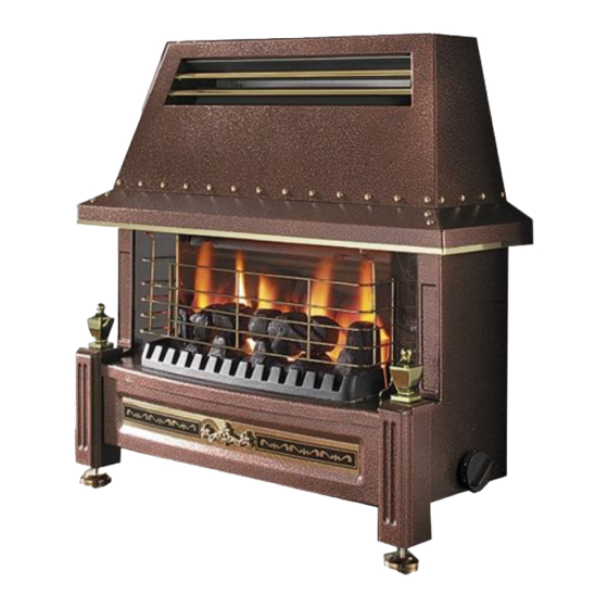
INSTALLATION INFORMATION CONDITIONS OF INSTALLATION It is the law that all gas appliances are installed only by a competent (e.g. Registered) Installer, in G.B. in accordance with the installation instructions and the Gas Safety (Installation and Use) Regulations 1998. Failure to install appliances correctly could lead to prosecution. - Page 26 ABOUT YOUR NEW FLAVEL REGENT LFE GAS FIRE The Flavel Regent L.F.E. gas fire incorporates a unique and highly developed fuelbed which gives good flame aeshetics whilst maintaining reasonable running costs. Please take the time to fully read these instructions as you will then be able to obtain the most effective and safe operation of your fire.
-
Page 27: Operating The Fire
OPERATING THE FIRE The Remote control handset generates an infrared signal, which will be received by the sensor situated at the front right of your fire, behind the black controls cover. This infrared signal requires direct line of sight from the handset to the sensor on the fire to ensure good operation. If the handset is lost or broken, the fire can be lit manually, see the user instructions for details on how to operate the fire manually. - Page 28 WARNING If the fire goes out for any reason or is turned off and it is necessary to relight the fire it is important to allow the fire to cool for 3 minutes before attempting to re-light it. TURNING THE PRODUCT OFF IN THE UNLIKELY EVENT OF A REMOTE HANDSET MALFUNCTION.
- Page 29 SPILLAGE MONITORING SYSTEM This appliance is fitted with a spillage monitoring system which shuts down the fire if the evacuation of combustion products from the fire is affected by a partially or fully blocked flue. If this system operates the fire will go out. If this occurs, leave the fire for at least three minutes then follow the lighting procedure as described in the previous sec- tion.
- Page 30 CLEANING THE DRESSGUARD OR REFLECTOR. Remove the dress-guard by pulling the location wire out at the top, and lifting away. See fig. 2 below. Clean the dress-guard or reflector by wiping with a damp cloth, and polish with a dry duster. DO NOT USE ABRASIVE CLEANERS CLEANING THE CASE.
- Page 31 REMOVAL / REFITTING OF THE FUELBED CERAMICS Fit the rear fuelbed section to the combustion chamber, locating behind the support bracket as indicated below in Fig. 3 Fig. 3 Fit rear section of fuelbed behind sup- port bracket as shown Fit the front section of the fuelbed to the combustion chamber, locating behind the front casting as shown overpage in Fig.
- Page 32 Due to our policy of continual improvement and development the exact accuracy of descriptions and illustrations cannot be guaranteed Part no. B-120510 Issue 3 BFM Europe Ltd Trentham Lakes Stoke-on-Trent Staffordshire ST4 4TJ www.bfm-europe.com Telephone - General Enquiries : (01782) 339000 Telephone - Service : (0844) 7700169...
Need help?
Do you have a question about the REGENT L.F.E. RC and is the answer not in the manual?
Questions and answers
flavel flames orange blue at base is this safe been told so looks real fire on coals but british gas condemned installer says this is how fire is not dangerous made to look realistic