
Related Manuals for HP 205 G1


Summary of Contents for HP 205 G1
- Page 1 Maintenance & Service Guide HP 205 G1 All-in-One Business PC HP 205 G2 All-in-One Business PC HP 18 All-in-One Business PC...
- Page 2 AMD is a trademark of Advanced Micro Devices, bound by the terms of the HP End User License Not all features are available in all editions of Inc. Bluetooth is a trademark owned by its Agreement (EULA).
-
Page 3: About This Book
About This Book WARNING! Text set off in this manner indicates that failure to follow directions could result in bodily harm or loss of life. CAUTION: Text set off in this manner indicates that failure to follow directions could result in damage to equipment or loss of information. - Page 4 About This Book...
-
Page 5: Table Of Contents
Table of contents 1 Product Features ............................1 Overview ................................1 Front components ..............................2 Top components ..............................2 Right components ..............................3 Left components ..............................4 Rear components ..............................5 2 Activating and Customizing the Software ......................6 Activating and customizing the software in Windows 10 ..................6 Activating the Windows Operating System .................. - Page 6 Routine care ................................. 15 General cleaning safety precautions ....................15 Cleaning the computer case ......................16 Cleaning the keyboard ........................16 Cleaning the display .......................... 16 Cleaning the mouse ........................... 17 Service considerations ............................17 Tools and software requirements ..................... 17 Screws ...............................
- Page 7 Why run HP PC Hardware Diagnostics ......................... 94 How to access and run HP PC Hardware Diagnostics ..................94 Downloading HP PC Hardware Diagnostics (UEFI) to a USB device ..............95 9 Backup and Recovery ........................... 96 Backing up, restoring, and recovering in Windows 10 ..................96 Creating recovery media and backups ....................
- Page 8 Removing the HP Recovery partition (select products only) ....... 99 Backup and recovery in Windows 8.1 ........................ 100 Backing up your information ......................100 Performing a system recovery ......................101 Using the Windows recovery tools ................101 Using f11 recovery tools ....................102 Using Windows 8.1 operating system media (purchased separately) ......
-
Page 9: Product Features
Wireless connectivity - HP WLAN/Bluetooth Combo NIC 802.11b/g/n Mini Card ● ● HP 205 G1 and HP 18 models: Integrated 1.0 MP 720p low-light webcam with microphone array HP 205 G2 models: Integrated VGA (640 x 480) webcam with mono microphone ●... -
Page 10: Front Components
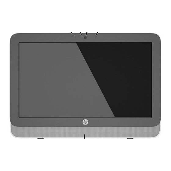
Front components Component Component Internal microphones (2) Webcam Webcam light Speaker Top components Component Power button Chapter 1 Product Features... -
Page 11: Right Components
Right components Component Optical drive Right components... -
Page 12: Left Components
Left components Component Component Drive light Audio-in (microphone) jack Memory card reader Audio-out (headphone) jack USB 3.0 ports (2) Chapter 1 Product Features... -
Page 13: Rear Components
Rear components Component Component Power connector USB ports (4) RJ-45 (network) jack Audio line-out jack Rear components... -
Page 14: Activating And Customizing The Software
5 to 10 minutes. Carefully read and follow the instructions on the screen to complete the activation. We recommend that you register your computer with HP during operating system set up so you can receive important software updates, facilitate support questions, and sign up for special offers. You can also register your computer with HP using the Register with HP app on the Start screen. -
Page 15: Activating And Customizing The Software In Windows 8.1
5 to 10 minutes. Carefully read and follow the instructions on the screen to complete the activation. We recommend that you register your computer with HP during operating system set up so you can receive important software updates, facilitate support questions, and sign up for special offers. You can also register your computer with HP using the Register with HP app on the Start screen. -
Page 16: Illustrated Parts Catalog
Boards and memory Item Component Spare part number System board (includes processor and replacement thermal material): For use in HP 205 G1 models: ● AMD E1-2500 APU for use in models with Windows 7 or without the Windows operating 751275-001 system ●... -
Page 17: Mass Storage Devices
Ralink RT5390R 802.11bgn Wi-Fi Adapter for use only in Brazil 806249-201 ● Wireless antenna kit 806248-001 Webcam HD, for use in HP 205 G1 and HP 18 models 752344-001 VGA, for use in HP 205 G2 and HP 18 models 806245-001 Memory module (PC3L-12800, 1666-MHz, DDR3): 4-GB... -
Page 18: Miscellaneous Parts
Miscellaneous parts Item Component Spare part number Speakers 752343-001 Hard drive screw bumpers 752334-001 752335-001 Front bezel 752331-001 Rear cover 752332-001 Display panel, 18.5-inch, anti-glare , LED N-ZBD, 200 nits 752345-001 Stand 752333-001 AC adapter (65 W) Standard efficiency 752346-001 89% efficient 806246-001 Mouse, USB... -
Page 19: Cables
Cables Component Spare part number Backlight cable 752330-001 Power button board cable 752336-001 Webcam cable 752337-001 Hard drive cable assembly 752338-001 Optical drive cable assembly 752339-001 LVDS (display) cable 752340-001 Converter board cable 752341-001 Cables... -
Page 20: Serial Ata (Sata) Drive Guidelines And Routine Care And Disassembly Preparation
6.0 Gb/s SATA hard drive cables SATA data cable Always use an HP approved SATA 3.0 Gb/s cable as it is fully backwards compatible with the SATA 1.5 Gb/s drives. Current HP desktop products ship with SATA 3.0 Gb/s hard drives. -
Page 21: Smart Ata Drives
SMART ATA drives The Self Monitoring Analysis and Recording Technology (SMART) ATA drives for the HP Personal Computers have built-in drive failure prediction that warns the user or network administrator of an impending failure or crash of the hard drive. The SMART drive tracks fault prediction and failure indication parameters such as reallocated sector count, spin retry count, and calibration retry count. -
Page 22: Personal Grounding Methods And Equipment
Keep electrostatic sensitive parts in their containers until they arrive at static-free stations. ● ● Place items on a grounded surface before removing them from their container. ● Always be properly grounded when touching a sensitive component or assembly. ● Avoid contact with pins, leads, or circuitry. -
Page 23: Operating Guidelines
● Conductive foam Conductive tabletop workstations with ground cord of one-megohm +/- 10% resistance ● ● Static-dissipative table or floor mats with hard tie to ground Field service kits ● ● Static awareness labels Wrist straps and footwear straps providing one-megohm +/- 10% resistance ●... -
Page 24: Cleaning The Computer Case
Disconnect the keyboard before cleaning it. Wear safety glasses equipped with side shields when cleaning the keyboard. Cleaning the computer case Follow all safety precautions in General cleaning safety precautions on page 15 before cleaning the computer. To clean the computer case, follow the procedures described below: ●... -
Page 25: Cleaning The Mouse
The screws used in the computer are not interchangeable. They may have standard or metric threads and may be of different lengths. If an incorrect screw is used during the reassembly process, it can damage the unit. HP strongly recommends that all screws removed during disassembly be kept with the part that was removed, then returned to their proper locations. -
Page 26: Cables And Connectors
In order to forward them to recycling or proper disposal, please use the public collection system or return them to HP, their authorized partners, or their agents. Chapter 4 Serial ATA (SATA) drive guidelines and routine care and disassembly preparation... -
Page 27: Removal And Replacement Procedures All-In One (Aio) Chassis
Disconnect all other attached cables from the back of the computer. Place the computer face down on a soft flat surface. HP recommends that you set down a blanket, towel, or other soft cloth to protect the screen surface from scratches or other damage. -
Page 28: Rear Cover
Rear cover Description Spare part number Rear cover 752332-001 The computer has one main rear cover that allows access to internal components. To remove the rear cover: Prepare the computer for disassembly (see Preparing to disassemble the computer on page 19). -
Page 29: Stand Assembly
Stand assembly Description Spare part number Stand assembly 752333-001 The stand is secured with four Torx screws. You must remove the rear cover to remove the stand. To remove the stand: Prepare the computer for disassembly (see Preparing to disassemble the computer on page 19). -
Page 30: Webcam Module
Webcam module Description Spare part number Webcam module, HD, for use in HP 205 G1 and HP 18 models 752344-001 Webcam module, VGA, for use in HP 205 G2 models 806245-001 On products that ship with a webcam module, the module is located at the top of the computer beneath the top panel. -
Page 31: Replacing Drives
Rotate the assembly to gain access to the connector on the module, and then disconnect the cable from the module. To remove the module from the bracket, remove the two Phillips screws that secure the module, and then separate the module from the bracket. To install a webcam module, reverse the removal procedures. - Page 32 Loosen the captive Phillips screw (1) that secures the hard drive cage to the computer, and then slide the cage toward the edge of the chassis to disengage it from the connector, and lift it out of the computer (2). NOTE: Hard drive cage appearance may vary.
- Page 33 2.5-inch hard drive: Remove the four Phillips screws (1) that secure the drive adapter to the cage, and then slide the drive out of the cage (2). Remove the four Phillips screws that secure the drive to the adapter (1), and the slide the drive out of the adapter (2).
-
Page 34: Replacing The Optical Disc Drive
Replacing the optical disc drive Description Spare part number DVD±RW drive 657958-001 Optical drive bezel 806247-001 The optical disc drive is located above the hard disc drive on the left side of the computer (when viewed from behind). The optical drive data cable connects to the SATA1 and SATA PWR1 system board connectors. NOTE: The drive bracket is not spared. - Page 35 Remove the two screws securing the optical disc drive bracket to the drive, and then remove the bracket. To replace the optical drive, reverse the removal procedures. Replacing drives...
-
Page 36: Front Bezel
Front bezel Description Spare part number Front bezel 752331-001 The front bezel is secured to the main system bracket with seven Torx screws. To remove the front bezel: Prepare the computer for disassembly (see Preparing to disassemble the computer on page 19). - Page 37 Disengage the nine tabs that secure the bezel to the computer (pointed out with white circles in the following illustration). NOTE: Although the following image shows the computer with most components removed, you can remove the bezel with all components installed except for the speakers. Lift the computer from the bezel.
-
Page 38: Converter Board
Converter board Description Spare part number Converter board 751276-001 The converter board is located on the left side of the computer (viewed from behind) under the main rear cover. It is secured with two Torx screws and has two connectors. Use the same converter spare part for all display panels;... - Page 39 Lift the converter board from the computer (3). To install the converter board, reverse the removal procedures. Converter board...
-
Page 40: Power Button Board
Power button board Description Spare part number Power button board 752342-001 The power button board is located on the top left of the computer (when viewed from behind). To remove the power button board: Prepare the computer for disassembly (see Preparing to disassemble the computer on page 19). - Page 41 Press on the tab that holds the power button board in place (2), and the remove the board from the computer. To install the power button board, reverse the removal procedures. Power button board...
-
Page 42: Speakers
Speakers Description Spare part number Speakers 752343-001 The speakers are located at the bottom of the computer. Two separate speakers are each secured by two Torx screws. To remove the speakers: Prepare the computer for disassembly (see Preparing to disassemble the computer on page 19). -
Page 43: Fan
Description Spare part number 752335-001 The fan is located near the middle of the computer and is secured with three Torx screws. You have to remove the metal plate to remove the fan. To remove the fan assembly: Prepare the computer for disassembly (see Preparing to disassemble the computer on page 19). - Page 44 Disconnect the fan cable from the system board connector labeled CHFAN2 (3). Remove the fan from the computer. To install the fan assembly, reverse the removal procedures. Chapter 5 Removal and Replacement Procedures All-in One (AIO) Chassis...
-
Page 45: Hard Drive And Optical Drive Cables And Connectors
Hard drive and optical drive cables and connectors Description Spare part number Optical drive cable 752339-001 Hard drive cable 752338-001 The hard drive and optical drive connectors are located near the middle of the computer. Each connector is secured with two Torx screws and has two cables that connect to the system board. The optical drive connector cables are longer than the hard drive connector cables. - Page 46 Remove the connector from the computer. To install the hard drive or optical drive connector, reverse the removal procedures. Chapter 5 Removal and Replacement Procedures All-in One (AIO) Chassis...
-
Page 47: System Board Cover
System board cover To remove the system board cover: Prepare the computer for disassembly (see Preparing to disassemble the computer on page 19). Remove the rear cover (see Rear cover on page 20). Remove the four Torx screws that secure the cover to the computer. System board cover... - Page 48 Lift the cover straight up and off the computer. To replace the lower panel, reverse the removal procedures. Chapter 5 Removal and Replacement Procedures All-in One (AIO) Chassis...
-
Page 49: Memory
Memory Description Spare part number 4-GB memory module (PC3-12800; SODOMM) 689373-001 2-GB memory module (PC3-12800; SODOMM) 689372-001 Memory modules are located on the right side of the computer (viewed from behind). The computer has two memory slots. For proper system operation, the SODIMMs must be: ●... - Page 50 Preparing to disassemble the computer on page 19). Place the computer face down on a soft flat surface. HP recommends that you set down a blanket, towel, or other soft cloth to protect the screen surface from scratches or other damage.
-
Page 51: Wlan Module
WLAN module Description Spare part number WLAN module for use in HP 205 G1 and HP 18 models: Ralink RT5390R 802.11bgn Wi-Fi Adapter 701399-001 WLAN module for use in HP 205 G2 models: HP Broadcom BCM943142HM 802.11 b/g/n WLAN + BT4.0 Mini Wireless Card 753076-001 Ralink RT5390R 802.11bgn Wi-Fi Adapter for use only in Brazil... -
Page 52: Rtc Battery
The lithium battery is only used when the computer is NOT connected to AC power. HP encourages customers to recycle used electronic hardware, HP original print cartridges, and rechargeable batteries. For more information about recycling programs, go to http://www.hp.com/recycle. -
Page 53: Remove The System Board Cover (See System Board Cover
Remove the system board cover (see System board cover on page 39). The battery can now be seen to the left of the heat sink. To release the battery from its holder, squeeze the metal clamp that extends above one edge of the battery. -
Page 54: System Board
System board Description Spare part number System board for use in HP 205 G1 models: ● AMD E1-2500 APU for use in models with Windows 7 or without the Windows operating system 751275-001 AMD E1-2500 APU for use in models with Windows 8.1 Standard 751275-501 ●... - Page 55 Remove the five Torx screws that secure the system board to the computer. Remove the system board. To install the system board, reverse the removal procedures. Updating SMBIOS Information When replacing the system board, you must reprogram the SMBIOS information on the affected computer. Failure to reprogram the board will result in eventual failure, such as an activation failure (need to reactivate the system) or a system recovery failure.
-
Page 56: Display Panel
Serial Number Enter the Serial Number of Unit. Support SKU Number Enter the SKU or Product Number including Localization Code. Support Asset Tag Enter the 18-byte identifier assigned to the computer. Support Feature Byte Enter the Feature Byte string. The feature byte string is case sensitive. Flexbuild The label includes spaces after every four characters. - Page 57 Disconnect the backlight cable from the display panel. NOTE: Replace the backlight cable with the new backlight cable that comes with the new display panel kit. Remove the backlight cable from the defective panel before sending the panel back to the supplier. Remove the four Torx screws (two on each side) that secure the display panel to the frame.
-
Page 58: Computer Setup (F10) Utility
Computer Setup (F10) Utility Computer Setup (F10) Utilities Use Computer Setup (F10) Utility to do the following: ● Change factory default settings. Set the system date and time. ● ● Set, view, change, or verify the system configuration, including settings for processor, graphics, memory, audio, storage, communications, and input devices. -
Page 59: Using Computer Setup (F10) Utilities
Using Computer Setup (F10) Utilities Computer Setup can be accessed only by turning the computer on or restarting the system. To access the Computer Setup Utilities menu, complete the following steps: Turn on or restart the computer. Repeatedly press when the power light turns white to access the utility. You can also press to a menu that allows you to access different options available at startup, including the Computer Setup utility. -
Page 60: Computer Setup-File
Computer Setup—File NOTE: Support for specific Computer Setup options may vary depending on the hardware configuration. Table 6-2 Computer Setup—File Option Description System Information Lists: ● Product name SKU number ● ● Processor type/speed/stepping ● Cache size (L1/L2/L3) (dual core processors have this listed twice) ●... -
Page 61: Computer Setup-Storage
Computer Setup—Storage NOTE: Support for specific Computer Setup options may vary depending on the hardware configuration. Table 6-3 Computer Setup—Storage Option Description Device Configuration Lists all installed BIOS-controlled storage devices. When a device is selected, detailed information and options are displayed. The following options may be presented: ●... -
Page 62: Computer Setup-Security
Table 6-3 Computer Setup—Storage (continued) NOTE: MS-DOS drive lettering assignments may not apply after a non-MS-DOS operating system has started. Shortcut to Temporarily Override Boot Order To boot one time from a device other than the default device specified in Boot Order, restart the computer and press (to access the boot menu) and then (Boot Order), or only... - Page 63 Table 6-4 Computer Setup—Security (continued) ● System audio ● USB controller (varies by model) ● Network controller NOTE: You must disable AMT before trying to hide the network controller. ● Serial port ● Parallel port SATA ports (varies by model) ●...
- Page 64 Table 6-4 Computer Setup—Security (continued) SVM CPU Virtualization (enable/disable). Controls the virtualization features of the processor. Changing this setting requires turning the computer off and then back on. Default is disabled. Virtualization Technology (VTx) (enable/disable) - Controls the virtualization features of the processor. Changing this setting requires turning the computer off and then back on.
- Page 65 (PK) that verifies kernels during system start up, allowing you to use alternative operating systems. Selecting HP Keys causes the computer boot using the preloaded HP-specific boot keys. Default is HP Keys.
-
Page 66: Computer Setup-Power
Computer Setup—Power NOTE: Support for specific Computer Setup options may vary depending on the hardware configuration. Table 6-5 Computer Setup—Power Option Description OS Power Management ● Idle Power Savings—Extended/Normal. Allows certain operating systems to decrease the processors power consumption when the processor is idle. Default is extended. ●... -
Page 67: Computer Setup-Advanced
Computer Setup—Advanced NOTE: Support for specific Computer Setup options may vary depending on the hardware configuration. Table 6-6 Computer Setup—Advanced (for advanced users) Option Heading Power-On Options Allows you to set: ● POST mode (QuickBoot, Clear Memory, FullBoot, or FullBoot Every x Days). ◦... - Page 68 Table 6-6 Computer Setup—Advanced (for advanced users) (continued) ● PCI VGA Palette Snooping is not used. Default is disabled. Device Options Allows you to set: ● Printer mode (Bi-Directional, EPP + ECP, Output Only). ECP = Enhanced Capabilities Port, EPP = Enhanced Parallel Port.
-
Page 69: Recovering The Configuration Settings
Recovering the Configuration Settings This method of recovery requires that you first perform the Save to Removable Media command with the Computer Setup (F10) Utility before Restore is needed. (See Computer Setup—File on page 52 in the Computer Setup—File table.) NOTE: It is recommended that you save any modified computer configuration settings to a USB flash media device and save the device for possible future use. -
Page 70: Troubleshooting Without Diagnostics
To assist you in resolving problems online, HP Instant Support Professional Edition provides you with self- solve diagnostics. If you need to contact HP support, use HP Instant Support Professional Edition's online chat feature. Access HP Instant Support Professional Edition at: http://www.hp.com/go/ispe. -
Page 71: Helpful Hints
If it becomes necessary to call for technical assistance, be prepared to do the following to ensure that your service call is handled properly: ● Be in front of your computer when you call. ● Write down the computer serial number, product ID number, and monitor serial number before calling. ●... -
Page 72: Solving General Problems
If you have installed an operating system other than the factory-installed operating system, check to be ● sure that it is supported on the system. If the system has multiple video sources (embedded, PCI, or PCI-Express adapters) installed (embedded ● video on some models only) and a single monitor, the monitor must be plugged into the monitor connector on the source selected as the primary VGA adapter. - Page 73 In case of forgotten password, power loss, or computer malfunction, you must manually disable the Smart Cover lock . A key to unlock the Smart Cover Lock is not available from HP. Keys are typically available from a hardware store.
- Page 74 Poor performance. Cause Solution Processor is too hot. Make sure airflow to the computer is not blocked. Leave a 10.2-cm (4-inch) clearance on all vented sides of the computer and above the monitor to permit the required airflow. Make sure fans are connected and working properly (some fans only operate when needed).
- Page 75 Poor performance. Cause Solution for suggestions on how to improve performance by adjusting parameters in the application. Add more memory. Upgrade the graphics solution. Cause unknown. Restart the computer. Computer powered off automatically and the Power LED flashes red four times and then white two times. Cause Solution Processor thermal protection activated:...
-
Page 76: Solving Power Problems
Solving power problems Common causes and solutions for power problems are listed in the following table. Power supply shuts down intermittently. Cause Solution If equipped with a voltage selector, voltage selector switch on Select the proper AC voltage using the selector switch. rear of computer chassis (some models) not switched to correct line voltage (115V or 230V). -
Page 77: Solving Hard Drive Problems
Solving hard drive problems Hard drive error occurs. Cause Solution Hard disk has bad sectors or has failed. In Windows 7, click Start, click Computer, and right-click on a drive. Select Properties, and then select the Tools tab. Under Error-checking click Check Now. In Windows 8.1, on the Start screen type e, and then select File Explorer from the list of applications. - Page 78 Drive not found (identified). Cause Solution The device is attached to a SATA port that has been hidden in Run the Computer Setup utility and ensure Device Available is Computer Setup. selected for the device's SATA port in Security > Device Security. Drive responds slowly immediately after power-up.
-
Page 79: Solving Media Card Reader Problems
Computer seems to be locked up. Cause Solution Program in use has stopped responding to commands. Use the task manager to close programs that do not respond. Attempt the normal Windows “Shut Down” procedure. If this fails, press the power button for four or more seconds to turn off the power. -
Page 80: Solving Display Problems
Do not know how to remove a media card correctly. Cause Solution The computer’s software is used to safely eject the card. In Windows 7, click Start, select Computer, right-click on the corresponding drive icon, and then select Eject. Pull the card out of the slot. - Page 81 (Beeps stop after fifth iteration but LEDs continue flashing.) Cause Solution Pre-video memory error. Reseat DIMMs. Power on the system. Replace DIMMs one at a time to isolate the faulty module. Replace third-party memory with HP memory. Replace the system board. Solving display problems...
- Page 82 Blank screen and the power LED flashes Red six times, once every second, followed by a two second pause, and the computer beeps six times. (Beeps stop after fifth iteration but LEDs continue flashing.) Cause Solution Pre-video graphics error. For systems with a graphics card: Reseat the graphics card (if applicable).
- Page 83 The picture is broken up, rolls, jitters, or flashes. Cause Solution The monitor connections may be incomplete or the monitor may Be sure the monitor cable is securely connected to the be incorrectly adjusted. computer. In a two-monitor system or if another monitor is in close proximity, be sure the monitors are not interfering with each other’s electromagnetic field by moving them apart.
- Page 84 To download a SoftPaq that will assist you with the synchronization, go to the following Web site, select the appropriate monitor, and download either SP32347 or SP32202: http://www.hp.com/support Graphics card is not seated properly or is bad (some models). Reseat the graphics card. Replace the graphics card.
-
Page 85: Solving Audio Problems
Certain typed symbols do not appear correct. Cause Solution In Windows 7, click Start, select All Programs, select Accessories, select System Tools, and then select Character Map. In Windows 8.1, on the Start screen, type ch, and then select Character Map from the list of applications. In Windows 10, type ch in the taskbar search box, and then select Character Map from the list of applications. - Page 86 Sound does not come out of the speaker or headphones. Cause Solution The application is set to use a different audio device than Some graphics cards support audio over the DisplayPort speakers. connection (if applicable), so multiple audio devices may be listed in Device Manager.
-
Page 87: Solving Printer Problems
There is no sound or sound volume is too low. Cause Solution To access Device Manager in Windows 8.1, from the Start screen, type c, select Control Panel from the list of applications, and then select Device Manager. To access Device Manager in Windows 10, type device manager in the taskbar search box, and then select Device Manager from the list of applications. -
Page 88: Solving Keyboard And Mouse Problems
Printer prints garbled information. Cause Solution The cables may not be connected properly. Reconnect all cables. Printer memory may be overloaded. Reset the printer by turning it off for one minute, then turn it back Printer will not print. Cause Solution The printer may be out of paper. - Page 89 Cursor will not move using the arrow keys on the keypad. Cause Solution enable the Num Lock key in Computer Setup at Advanced > Device Options. Mouse does not respond to movement or is too slow. Cause Solution Mouse connector is not properly plugged into the back of the Shut down the computer using the keyboard.
-
Page 90: Solving Hardware Installation Problems
Mouse will only move vertically, horizontally, or movement is jerky. Cause Solution Mouse roller ball or the rotating encoder shafts that make contact Remove roller ball cover from the bottom of the mouse and clean with the ball are dirty. the internal components with a mouse cleaning kit available from most computer stores. -
Page 91: Solving Network Problems
DIMM1 or XMM1 must always be installed. DIMM1 must be installed before DIMM2, and DIMM3 must be installed before DIMM4 Replace third-party memory with HP memory. Replace the system board. Solving Network Problems Some common causes and solutions for network problems are listed in the following table. These guidelines do not discuss the process of debugging the network cabling. - Page 92 Table 7-2 Solving Network Problems (continued) Network driver does not detect network controller. Cause Solution To access Device Manager in Windows 10, type device manager in the taskbar search box, and then select Device Manager from the list of applications. Incorrect network driver.
- Page 93 Diagnostics reports a failure. Cause Solution The cable is not securely connected. Ensure that the cable is securely attached to the network connector and that the other end of the cable is securely attached to the correct device. The cable is attached to the incorrect connector. Ensure that the cable is attached to the correct connector.
-
Page 94: Solving Memory Problems
Management Engine (ME) settings). To avoid damage to the DIMMs or the system board, you must unplug the computer power cord before attempting to reseat, install, or remove a memory module. For those systems that support ECC memory, HP does not support mixing ECC and non-ECC memory. Otherwise, the computer will not boot the operating system. - Page 95 LEDs continue flashing.) Cause Solution Memory is installed incorrectly or is bad. Reseat DIMMs. Power on the system. Replace DIMMs one at a time to isolate the faulty module. Replace third-party memory with HP memory. Replace the system board. Solving memory problems...
-
Page 96: Solving Cd-Rom And Dvd Problems
Solving CD-ROM and DVD problems If you encounter CD-ROM or DVD problems, see the common causes and solutions listed in the following table or to the documentation that came with the optional device. System will not boot from CD-ROM or DVD drive. Cause Solution The device is attached to a SATA port that has been hidden in the... - Page 97 Movie will not play in the DVD drive. Cause Solution Decoder software is not installed. Install decoder software. Damaged media. Replace media. Movie rating locked out by parental lock. Use DVD software to remove parental lock. Media installed upside down. Reinstall media.
-
Page 98: Solving Usb Flash Drive Problems
Recording or copying CDs is difficult or impossible. Cause Solution Try a different brand of media. Quality varies widely between manufacturers. Solving USB flash drive problems If you encounter USB flash drive problems, common causes and solutions are listed in the following table. USB flash drive is not seen as a drive letter in Windows. -
Page 99: Solving Front Panel Component Problems
Solving front panel component problems If you encounter problems with devices connected to the front panel, refer to the common causes and solutions listed in the following table. A USB device, headphone, or microphone is not recognized by the computer. Cause Solution Device is not properly connected. - Page 100 Unable to connect to the Internet. Cause Solution In the Browsing history section on the General tab, click the Delete button. Select the Cookies check box and click the Delete button. Windows 8.1: From the Start screen, type c, and then select Control Panel from the list of applications.
-
Page 101: Solving Software Problems
● sure it is supported on the system. If you encounter software problems, see the applicable solutions listed in the following table. Computer will not continue and the HP logo does not display. Cause Solution ROM issue - POST error has occurred. -
Page 102: Hp Pc Hardware Diagnostics
Why run HP PC Hardware Diagnostics The HP PC Hardware Diagnostic tools simplify the process of diagnosing hardware issues and expedite the support process when issues are found. The tools save time by pinpointing the component that needs to be replaced. -
Page 103: Downloading Hp Pc Hardware Diagnostics (Uefi) To A Usb Device
Downloading HP PC Hardware Diagnostics (UEFI) to a USB device NOTE: Instructions for downloading HP PC Hardware Diagnostics (UEFI) are provided in English only. There are two options to download HP PC Hardward Diagnostics to USB device. Option 1: HP PC Diagnostics homepage–Provides access to the latest UEFI version Go to http://www.hp.com/go/techcenter/pcdiags. -
Page 104: Backup And Recovery
Use HP Recovery Manager to create HP Recovery media after you successfully set up the computer. This ● step creates a backup of the HP Recovery partition on the computer. The backup can be used to reinstall the original operating system in cases where the hard drive is corrupted or has been replaced. For... -
Page 105: Using Windows Tools
DVD-R, DVD+R, DVD-R DL, or DVD+R DL discs. Do not use rewritable discs such as CD±RW, DVD±RW, double-layer DVD±RW, or BD-RE (rewritable Blu-ray) discs; they are not compatible with HP Recovery Manager software. Or, instead, you can use a high- quality blank USB flash drive. -
Page 106: Recovering Using Hp Recovery Manager
Creating HP Recovery media (select products only) on page ● If your computer does not allow the creation of HP Recovery media or if the HP Recovery media does not work, you can obtain recovery media for your system from support. See the Worldwide Telephone Numbers booklet included with the computer. -
Page 107: Using The Hp Recovery Partition (Select Products Only)
Using HP Recovery media to recover You can use HP Recovery media to recover the original system. This method can be used if your system does not have an HP Recovery partition or if the hard drive is not working properly. -
Page 108: Backup And Recovery In Windows 8.1
For detailed instructions on various backup and restore options, perform a search for these topics in Help and Support. From the Start screen, type h, and then select Help and Support. In case of system instability, HP recommends that you print the recovery procedures and save them for later use. -
Page 109: Performing A System Recovery
From the Start screen, type c, and then select Computer. NOTE: If the Windows partition and the HP Recovery partition are not listed, you must recover your operating system and programs using the Windows 8.1 operating system media and the Driver Recovery media (both purchased separately). -
Page 110: Using F11 Recovery Tools
Software not installed at the factory must be reinstalled. To recover the original hard drive image using f11: If possible, back up all personal files. If possible, check for the presence of the HP Recovery partition: From the Start screen, type C, and then select Computer. NOTE: If the HP Recovery partition is not listed, you must recover your operating system and programs using the Windows 8.1 operating system media, and the Driver Recovery media (both purchased... -
Page 111: 10 Post Error Messages
10 POST Error Messages This appendix lists the error codes, error messages, and the various indicator light and audible sequences that you may encounter during Power-On Self-Test (POST) or computer restart, the probable source of the problem, and steps you can take to resolve the error condition. POST Message Disabled suppresses most system messages during POST, such as memory count and non- error text messages. - Page 112 Memory configuration incorrect. Run Computer Setup or Windows utilities. Make sure the memory module(s) are installed properly. If third-party memory has been added, test using HP-only memory. Verify proper memory module type. 201-Memory Error RAM failure. Ensure memory modules are correctly installed.
- Page 113 System test using F2 Diagnostics. Apply hard drive firmware patch if applicable. (Available at http://www.hp.com/support.) Back up contents and replace hard drive. 1796-SATA Cabling Error One or more SATA devices are improperly Ensure SATA connectors are used in ascending attached.
- Page 114 Table 10-1 Numeric Codes and Text Messages (continued) Control panel message Description Recommended action Drivelock is Disabled. Lastly, change Storage > Storage Options > SATA Emulation back to RAID and select File > Save Changes and Exit. 1801-Microcode Patch Error Processor is not supported by ROM BIOS.
- Page 115 Table 10-1 Numeric Codes and Text Messages (continued) Control panel message Description Recommended action If the error still persists, replace the system board. 2205-Interface error during MEBx execution MEBx operation experienced a hardware error Reboot the computer. during communication with ME. If the error persists, update to the latest BIOS version.
- Page 116 Table 10-1 Numeric Codes and Text Messages (continued) Control panel message Description Recommended action handles transference of information between If the error still persists, replace the the system BIOS and ME firmware. system board. 2231-ME error during MEBx execution Error occurred during MEBx execution which Reboot the computer.
-
Page 117: Interpreting Post Diagnostic Front Panel Leds
LEDs continue until problem Reseat SODIMMs. is solved. Replace SODIMMs one at a time to isolate the faulty module. Replace third-party memory with HP memory. Replace the system board. Red Power LED flashes six times, Pre-video graphics error. Replace the system board. - Page 118 Table 10-2 Diagnostic front panel LEDs and audible codes (continued) Activity Beeps Possible Cause Recommended Action but LEDs continue until problem is solved. Red Power LED flashes eight Invalid ROM based on bad Reflash the system ROM with the latest BIOS times, once every second, checksum.
-
Page 119: 11 Password Security And Resetting Cmos
11 Password Security and Resetting CMOS This computer supports security password features, which can be established through the Computer Setup Utilities menu. This computer supports two security password features that are established through the Computer Setup Utilities menu: setup password and power-on password. When you establish only a setup password, any user can access all the information on the computer except Computer Setup. -
Page 120: Resetting The Setup And Power-On Password
The password jumper is blue so that it can be easily identified. For assistance locating the password jumper and other system board components, see the Illustrated Parts & Service Map (IPSM). The IPSM can be downloaded from http://www.hp.com/support. Remove the jumper. - Page 121 Turn off the computer and any external devices, and disconnect the power cord from the power outlet. Disconnect external equipment connected to the computer. WARNING! To reduce the risk of personal injury from electrical shock and/or hot surfaces, be sure to disconnect the power cord from the wall outlet, and allow the internal system components to cool before touching.
- Page 122 NOTE: You will receive POST error messages after clearing CMOS and rebooting advising you that configuration changes have occurred. Use Computer Setup to reset any special system setups along with the date and time. For instructions on Computer Setup, see Computer Setup (F10) Utility on page 114 Chapter 11 Password Security and Resetting CMOS...
-
Page 123: Appendix A Power Cord Set Requirements
Power Cord Set Requirements The power supplies on some computers have external power switches. The voltage select switch feature on the computer permits it to operate from any line voltage between 100-120 or 220-240 volts AC. Power supplies on those computers that do not have external power switches are equipped with internal switches that sense the incoming voltage and automatically switch to the proper voltage. -
Page 124: Country-Specific Requirements
Country-specific requirements Additional requirements specific to a country are shown in parentheses and explained below. Country Accrediting Agency Country Accrediting Agency Australia (1) EANSW Italy (1) Austria (1) Japan (3) METI Belgium (1) CEBC Norway (1) NEMKO Canada (2) Sweden (1) SEMKO Denmark (1) DEMKO... -
Page 125: Appendix B Specifications
Specifications Specifications Dimensions 12.96 in 329 mm Height 18.51 in 470 mm Width 2.83 in 72 mm Depth Approximate Weight (with stand) 12 lbs 5.5 kg Temperature Range 41° to 95°F 5° to 35°C Operating -22° to 149°F -30° to 65°C Nonoperating Relative Humidity (non-condensing) 15-80%... -
Page 126: Index
9 disposal 18 spare part number 10, 48 hardware installation problems 82 battery replacement 44 helpful hints 63 booting options HP PC Hardware Diagnostics (UEFI) electrostatic discharge (ESD) 13 Full Boot 103 downloading 95 preventing damage 13 error cable pinouts... - Page 127 memory CD-ROM or DVD 88 problems 86 Computer Setup 64 safety and comfort 62 memory module F10 Setup 64 safety precautions removing 41 flash drive 90 cleaning 15 spare part numbers 9, 41 front panel 91 SATA monitor problems 72 general 64 connectors on system board 12 mouse...
- Page 128 webcam module removing 22 spare part number 22 Windows 10 backup and restore 96 Windows 8.1 operating system DVD 102 WLAN module removing 43 spare part number 9, 43 120 Index...
Need help?
Do you have a question about the 205 G1 and is the answer not in the manual?
Questions and answers