Table of Contents
Advertisement
Quick Links
Advertisement
Table of Contents

Related Manuals for Sanwa CD770


Summary of Contents for Sanwa CD770
- Page 1 CD770 DIGITAL MULTIMETER 取扱説明書 INSTRUCTION MANUAL...
- Page 3 目 次 【1】安全に関する項目∼ご使用の前に必ずお読みください。∼ 1−1 警告マークなどの記号説明 ………………………………001 1−2 安全使用のための警告文 …………………………………001 1−3 過負荷保護 …………………………………………………002 【2】用途と特長 2−1 用 途 ………………………………………………………003 2−2 特 長 ………………………………………………………003 【3】各部の名称 3−1 本体 …………………………………………………………004 3−2 テストリード ………………………………………………004 3−3 表示器 ………………………………………………………005 【4】機能説明 …………………………………………………………006 4−1 電源スイッチ兼ファンクションスイッチ ………………006 4−2 測定機能選択: ……………………………………006 4−3 データホールド: ………………………………006 4−4...
- Page 4 【1】安全に関する項目∼ご使用の前に必ずお読みください。∼ このたびはデジタルマルチメータCD770型をお買い上げいただ き、誠にありがとうございます。 ご使用前にはこの取扱説明書をよくお読みいただき、正しく安全 にご使用ください。そして常にご覧いただけるように製品と一緒に して大切に保管してください。 本書で指定していない方法で使用すると、本製品の保護機能が損な われることがあります。 ・・・ ・ 本文中の“ 警告”および“ 注意”の記載事項は、やけどや感 ・ 電などの事故防止のため、必ずお守りください。 1-1 警告マークなどの記号説明 本器および『取扱説明書』に使用されている記号と意味について :安全に使用するための特に重要な事項を示します。 ・警告文はやけどや感電などの人身事故を防止するためのものです。 ・注意文は本器を壊すおそれのあるお取扱や測定に対しての注 意文です。 :高電圧注意 :グランド :直流(DC) :周波数 :交流(AC) :コンデンサ : 抵 抗 : ヒ ュ ー ズ :ダイオード :二重絶縁または強化絶縁 :ブザー 1-2 安全使用のための警告文...
- Page 5 16. 本体またはテストリードが傷んでいたり、壊れていたりして いる場合は使用しないこと。 17. ケースまたは電池ふたを外した状態では使用しないこと。 18. ヒューズは必ず指定定格および仕様のものを使用すること。 19. 測定中はテストリードのつばよりテストピン側を持たないこと。 10. 測定する場合は最初に接地側(テストリードの黒)を接続し、 離す場合は最後に接地側を離すこと。 11. 測定中は他のファンクションまたは他のレンジに切り換えた り、プラグを他の端子へ差し換えたりしないこと。 12. 測定前には、 ファンクションおよびレンジ確認を確実に行うこと。 13. 本器または手が水等でぬれた状態での使用はしないこと。 14. テストリードは指定タイプのものを使用すること。 15. 電池交換およびヒューズ交換を除く修理 ・ 改造は行わないこと。 16. 年1回以上の点検は必ず行うこと。 17. 屋内で使用すること。 1-3 過負荷保護 各ファンクション入力端子の最大定格入力値および過負荷保護を定めています。 ファンクション 入力端子 最大定格入力値 最大過負荷保護入力値 V・Hz DC/AC 600 V 電圧・電流...
- Page 6 【2】用途と特長 2-1 用 途 本器は弱電回路の測定用に設計された、デジタルマルチメータで す。小型通信機器や家電製品、各種電池などの測定はもちろん、付 加機能を使って回路分析などに威力を発揮します。 2-2 特 長 ・電流端子にはテス ト リー ド誤挿入を抑制するセーフティーキャ ップ付き ・数値が大きく見易い表示器 ・周波数測定および静電容量測定機能付 ・手に持ちやすいデザイン ・本体にテストプローブをホールド可能 ・二重成形で、外側は弾力性のあるエラストマー素材を使用 − 3 −...
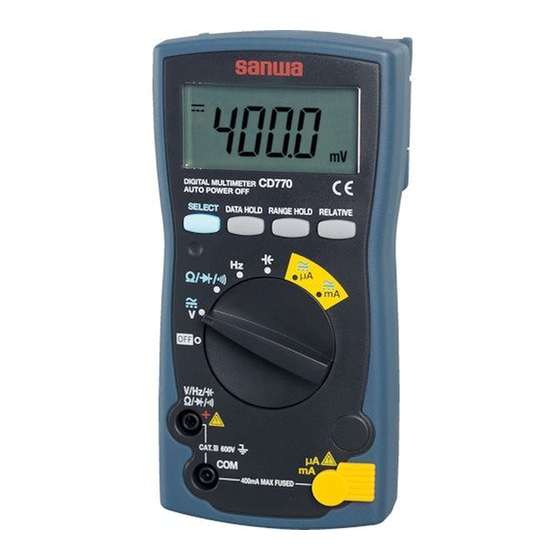
- Page 7 【3】各部の名称 3-1 本体 液晶表示部 セレクトボタン レンジホールド ボタン リラティブボタン 電源スイッチ兼 データホールボタン ファンクションスイッチ セーフティーキャップ 測定端子 μA COM (共通) 端子 測定端子 3-2 テストリード 着脱式 未装着時 テス ト ピン キ ャ ッ プ テストピン つば テ ス ト プロー ブ (赤) プラグ テ ス ト プロー ブ (黒) TL-21a −...
- Page 8 3-3 表示器 ① 数値表示 ② リラティブモード動作表示 ③ 数値データのマイナス極性表示 ④ 交流測定ファンクション動作表示 ⑤ 直流測定ファンクション動作表示 ⑥ オートレンジモード動作表示 ⑦ 本器では使用しません ⑧ ダイオードテストファンクション動作表示 ⑨ 導通チェックファンクション動作表示 ⑩ データホールドモード動作表示 ⑪ リラティブモード動作表示 ⑫ 電池消耗警告表示 ⑬ 測定単位表示 − 5 −...
- Page 9 【4】機能説明 4-1 電源スイッチ兼ファンクションスイッチ このスイッチを回して電源のON/OFFと各測定ファンクションを 切り換えます。 4-2 測定機能選択: ボタンを押すと、ファンクションは以下のように切り換わ ります。 ・Vポジション:直流電圧( )→ 交流電圧( )→ 直流電圧( ) ・ / / ポジション:抵抗測定( )→ ダイオードテスト( ) → 導通チェック( )→ 抵抗測定( ) ・μAポジション:直流電流 ( )→ 交流電流 ( ) → 直流電流 ( ) ・mAポジション:直流電流 ( )→ 交流電流 ( ) → 直流電流 ( ) 4-3 データホールド:...
- Page 10 4-5 リラティブ測定(相対値測定) : ボタンを押すと、 と が点灯し、 押した時点の入力値 を基準とし0と表示します。 解除にするにはボタンを再度押してください。 例)DC 30.00 V入力時にボタンを押した後の表示 実際の入力値 表示器の数値 DC 30.00 V DC 00.00 V DC 35.00 V DC 05.00 V DC 25.00 V DC −05.00 V 備考: ファンクションでは、使用できません。また 以外のファンク ションでは、リラティブ測定時はレンジが固定されます。 4-6 オートパワーオフ 電源ON時からスイッチやボタン操作が行われないとき、約30分後に 自動的に電源が切れ表示が全て消えます。 復帰する場合はいずれかのボタンを押すか、被測定物を一度DMMか...
- Page 11 2. 本体およびテストリードが傷んでいたり、壊れていたりして いる場合は使用しないこと。 3. テストリードおよびヒューズが切れていないことを確認する こと。 安全のため、 必ず始業点検を行ってください。 ( 導通チェックによる点検) 確 認 ※ 点検終了です。 ※表示器に何も表示が出ない場合は、 電池の全消耗が考えられます。 − 8 −...
- Page 12 5-2 電圧測定(V) ファンクション 最大定格入力 レンジ DC 600 V 400.0 mV, 4.000 V, 40.00 V, 400.0 V, 600 V AC 600 V 4.000 V, 40.00 V, 400.0 V, 600 V DCV測定例 ACV測定例 DCVとACV 切替 備考: 本器の交流検波方式は平均値方式です。正の半周期間の電圧また は電流を平均して値を表示します。入力波形が正弦波で歪のない 波形測定の時には誤差は生じませんが、入力波形が歪正弦波や非 正弦波の時は誤差を生じます。 ・テストリード開放時に表示が変動する場合がありますが故障で はありません。 ・AC 400.0 mVレンジは...
- Page 13 5-3 抵抗測定 ( ) 、ダイオードテスト ( ) 、導通チェック ( ) 警 告 警 告 測定端子には外部から電圧を絶対に加えないこと。 5-3-1 抵抗測定( ) ファンクション 最大定格入力 レンジ 400.0 Ω, 4.000 kΩ, 40.00 kΩ, 40.00 MΩ 400.0 kΩ,4.000 MΩ, 40.00 MΩ 備考: 抵抗器 測定に際しノイズの影響を 受ける場合は、被測定物を COM電位でシールドしてく ださい。また、テストピン に...
- Page 14 5-3-3 導通チェック( ) 備考: 導 通 ブ ザ ー 発 音 範囲:0 Ω∼85 Ω 抵抗測定 (±45 Ω) ダイオー ドテス ト 導通チェック 切替 5-4 周波数測定 ( ) 注 意 測定禁止 対接地間の周波数測定は、漏電ブレーカー 等が動作する可能性がありますので、絶対 に行わないでください。 ファンクション 最大定格入力 レンジ 100.0 kHz 5.000 Hz, 50.00 Hz, 500.0 Hz, 5.000 kHz, (≦600 Vrms)...
- Page 15 備考: ・入力感度: 3 Vrms以上 ・ゼロクロス(+電位 →−電位 → +電位)している周波数が測定で きます。ロジックパルスのような+電位のみまたは−電位のみ の周波数は測定できません。 ・1 Hz未満の測定はできません。 ・Hzファンクションではデータホールド及びリラティブ機能は、 使用できません。 5-5 静電容量測定( ) 警 告 測定端子には外部から電圧を絶対に加えないこと。 注 意 1. コンデンサ内の電荷は測定前に放電すること。 2. 本器は被測定コンデンサに電流を加える測定方式のため、漏 れ電流の大きい電解コンデンサなどの測定は誤差が大きくな るために適しません。 3. 静電容量の大きいコンデンサ測定では、 測定時間が長くなります。 ファンクション 最大定格入力 レンジ 50.00 nF, 500.0 nF, 5.000 μF, 100.0 μF CAP(...
- Page 16 5-6 電流測定(μA/mA) 警 告 1. 測定端子には電圧を絶対に加えないこと。 2. 最大定格電流を超える入力は加えないこと。 3. 必ず負荷を通して本器が直列に接続されること。 正しい測定方法 誤った測定方法 電 源 負 電 荷 源 負 荷 注 意 内蔵ヒューズが切れていないかご確認ください。 ファンクション 最大定格入力 レンジ DC/AC μA 4000 μA 400.0 μA, 4000 μA DC/AC mA 400 mA 40.00 mA, 400.0 mA 備考:...
- Page 17 μA・m A 測定 負 フ ァ ンクシ ョ ン 入力端子 使用内蔵ヒューズ 電 荷 源 0.5 A/250 Vヒュ ーズ と 遮断容量1.5 kA ・入力信号を加えても表示がほとんど変化しない場合や、予想した 電流値より著しく小さい値の場合は、入力端子やファンクション スイッチの位置が違っていたり、ヒューズが遮断している可能性 がありますので確認を行ってください。 − 14 −...
- Page 18 【6】保守管理について 警 告 1. この項目は安全上重要です。 本説明書をよく理解した上で管理を行ってください。 2. 安全と確度維持のために1年に1回以上は校正、 点検を行ってください。 6-1 保守点検 1)外観:落下などにより、外観が壊れていないか? 2)テストリード: ・テストリードから芯線が露出していないか? ・入力端子にプラグを差し込んだときに緩みはないか? 以上の項目に該当するものはそのまま使用せず、修理を依頼 してください。 6-2 校正・点検 詳細については三和電気計器 (株) までお問い合わせください。 項目7-3を参照。 6-3 保管について 注 意 1. 本体は揮発性溶剤に弱いため、シンナーやアルコールなどで 拭かないこと。 2. 本体は熱に弱いため、高熱を発するものの近くに置かないこと。 3. 振動の多い場所や落下のおそれのある場所に保管しないこと。 4. 直射日光や高熱、低温、多湿、結露のある場所での保管は避 けること。 5. 長期間使用しない場合は内蔵電池を必ず抜いておくこと。 6-4 電池、ヒューズの交換 出荷時の電池について...
- Page 19 警 告 1. 感電のおそれがあるため、測定端子に入力が加わった状態で リヤケースを外さないこと。また、ファンクションスイッチが OFFになっていることを確認し作業を行うこと。 2. 交換用ヒューズは同定格のものを使用すること。ヒューズの 代用品を用いたり、短絡したりすることは絶対にしないこと。 6-4-1 電池交換 ①電池ホルダ固定ネジをプラスドライバーで外します。 ②電池ホルダ内の電池を2本共に新品と交換します。 (電池極性にご注意ください。 ) ③電池ホルダ固定ネジを元どおりネジ止めします。 使用電池 単 3 電池 (R6)2本 6-4-2 ヒューズ交換 ①本体リアケースのネジをドライバーで外します。 ②内部にあるヒューズを取り出し、新しいヒューズと交換します。 ③リヤケースを元どおりねじ止めします。 ヒューズ 使用ヒューズ定格 0.5 A/250 V(φ5×20 mm、遮断容量1.5 kA) ※リアケース下部に予備ヒューズ収納場所があります。 − 16 −...
- Page 20 【7】アフターサービスについて 7-1 保証期間について 本製品の保証期間は、お買い上げの日より3年間です。 ただし、日本国内で購入し日本国内でご使用いただく場合に 限ります。また、製品本体の確度および許容差は1年保証、製 品付属の電池、ヒューズ、テストリード等は保証対象外とさせ ていただきます。 7-2 修理について 1)修理依頼の前にもう一度次の項目をご確認ください。 ・内蔵電池の容量と電池装着時の極性をチェック。 ・内蔵ヒューズとテストリードの断線をチェック。 2)保証期間中の修理:保証書の記載内容によって修理させてい ただきます。 3)保証期間経過後の修理 修理および輸送費用が製品価格より高くなる場合もあります ので、事前にお問い合わせください。補修用性能部品の最低 保有期間は、製造打切り後6年間です。この保有期間を修理可 能期間とさせていただきます。ただし、性能部品が製造中止 などにより入手不可能になった場合は、保有期間が短くなる 場合もあります。 4)修理品の送り先 製品(本体およびテストリード等の付属品を含む)の安全輸 送のため、製品の5倍以上の容積の箱に入れ、十分なクッショ ンを詰め、箱の表面に「修理品在中」と明記して送りくださ い。輸送にかかる往復の送料は、お客様のご負担とさせてい ただきます。 [送り先]三和電気計器株式会社・羽村工場サービス課 〒205-8604 東京都羽村市神明台4-7-15 TEL(042) 554-0113/FAX(042) 555-9046 − 17 −...
- Page 21 φ5×20 mm 0.5 A/250 V 1.5 kA ¥200 ( 税込) ¥120 ( 10本迄) 7-3 お問い合わせ 三和電気計器株式会社 本 社 :TEL(03) 3253-4871/ FAX(03) 3251-7022 大阪営業所 :TEL(06) 6631-7361/ FAX(06) 6644-3249 お客様計測相談室: 0120-51-3930 受付時間9:30∼12:00 13:00∼17:00(土日祭日を除く) ホ ー ム ペ ー ジ:http://www.sanwa-meter.co.jp − 18 −...
- Page 22 【8】仕 様 8-1 一般仕様 Δ-Σ方式 動作方式 交流検波方式 平均値方式 液晶表示器 4000カウント サンプルレート 約3回/秒 レンジ切り換え オート及びマニュアル (一部マニュアルまた はオートのみ) オーバー表示 数値部に''OL''を表示 (DC/AC 600 Vを除く) 極性表示自動切換 マイナス入力時に''−''のみ表示 電池消耗警告 約2.4 V以下でバッテリー ( ) マークが点 灯または点滅 使用環境条件 高度2000 m以下・環境汚染度Ⅱ 動作温度/湿度 5 ℃∼40 ℃ 湿度は下記のとおりで結露のないこと 5 ℃∼31 ℃で80 %RH (最大) 、 31 ℃以上40 ℃では80 %RHから50 %RHへ直線的に減少...
- Page 23 8-2 測定範囲および確度 温度:23±5 ℃ 湿度:80 %R.H.以下(結露のないこと) 、電源電 圧2.4 V以上 rdg(reading):読み取り値 dgt(digit):最終桁のカウント数 DCV直流電圧 レンジ 確 度 入力抵抗 備 考 400.0 mV ± (0.5 %rdg+2dgt) ≧約100 MΩ 約11 MΩ 4.000 V 40.00 V ± (0.9 %rdg+2dgt) 約10 MΩ 400.0 V 600 V ACV 交流電圧...
- Page 24 周波数 レ ン ジ 確 度 備 考 ・オートレンジのみ 5.000 Hz ・データホールド及びリラティブ機能は使用できません。 ・感度: 3 Vrms以上 50.00 Hz ・1 Hz未満は測定できません。 500.0 Hz ・入力抵抗 ≧約2 kΩ ± (0.3 %rdg+3dgt) 入力抵抗が約2 kΩと非常に低いので、 測定時には多 5.000 kHz くの電流が流れます。電流容量の小さい回路や装置 の測定は絶対に行わないでください。 50.00 kHz 対接地間の周波数測定は、漏電ブレーカー等が動作す 100.0 kHz る可能性がありますので、絶対に行わないでください。 静電容量測定...
- Page 25 ※トランスや大電流路など強磁界の発生している近く、また無線機 など強電界の発生している近くでは正常な測定ができない場合が あります。 確度計算方法 例) 直流電流測定(DCV) 真 値:100 mV レンジ確度:400 mVレンジ……± (0.5 %rdg+2dgt) 誤 差:±(100.0 mV × 0.5 % + 2dgt)= ±0.7 mV 表 示 値:100.0 mV ± 0.7 mV (99.3 mV∼100.7 mVの範囲内) ここに掲載した製品の仕様や外観は改良等の理由により、予告なし に変更することがありますのでご了承ください。 − 22 −...
- Page 26 MEMO...
- Page 27 保証書 ご氏名 CD770 型 名 様 製造No. ご住所 この製品は厳密なる品質管理を経てお 〒 届けするものです。 本保証書は所定項目をご記入の上保管 していただき、アフターサービスの際 ご提出ください。 ※本保証書は再発行はいたしませんの で大切に保管してください。 保証期間 本社 = 東京都千代田区外神田2−4−4 ・ 電波ビル ご購入日 年 月より 3 年間 郵便番号 = 101-0021・電話=東京 (03) 3253−4871 (代) 保証規定 保証期間中に正常な使用状態のもとで、万一故障が発生した場合には無償で修理いたします。 ただし下記事項に該当する場合は無償修理の対象から除外いたします。 記 1. 取扱説明書と異なる不適当な取扱いまたは使用による故障 2. 当社サービスマン以外による不当な修理や改造に起因する故障...
- Page 29 CD770 DIGITAL MULTIMETER INSTRUCTION MANUAL...
-
Page 31: Table Of Contents
5-6 Current Measurement ( 【6】MAINTENANCE 6-1 Maintenance and Inspection 6-2 Calibration and Inspection 6-3 Storage 6-4 Battery and Fuse Replacement 【7】After-Sale Service 7-1 Warranty and Provision 7-2 Repair 7-3 SANWA web site 【8】SPECIFICATIONS 8-1 General Specifications 8-2 Measuring Range and Accuracy... - Page 32 Before use, please read this manual thoroughly to ensure correct and safe use. After reading it, keep it together with the product for reference to it when necessary. Using this product in ways not specified in this manual may damage its protection function. The instructions given under the headings of “...
-
Page 33: Overload Protection
5. Never use the meter near equipment which generates strong electromagnetic waves or is charged. 6. Never use the meter if the meter or test leads are damaged or broken. 7. Never use the meter with the case or battery lid removed. 8. -
Page 34: Applications And Features
[2] APPLICATIONS AND FEATURES 2-1 Applications This is a digital multimeter designed for measurement of low- voltage circuits. This meter is useful for measuring / analyzing circuits of small communication devices, home electric appliances and batteries. 2-2 Features The current terminal is protected with a safety cap. Easy-to-read display showing Eye-friendly large size LCD. -
Page 35: Names Of Component Units
[3] NAMES OF COMPONENT UNITS 3-1 Meter Select button Range hold button Relative button Data hold button Power switch & function switch Safety cap Measuring terminal μ A/mA COM (common) terminal Measuring terminal 3-2 Test Leads — 4 —... -
Page 36: Display
3-2 Display Indication of numerical value. Indication of relative mode operation. Indication of negative sign of numerical data. Indication of AC measuring function operation. Indication of DC measuring function operation. Indication of auto range mode operation. Not used with this meter. Indication of diode test function operation. -
Page 37: Description Of Functions
[4] DESCRIPTION OF FUNCTIONS 4-1 Power Switch & Function Switch Turn this switch to turn on and off the power and select a measuring function. 4-2 Measuring Function Selection: When the button is pressed, the functions change as follows: V position: DC voltage ( AC voltage ( DC voltage ( position: Resistance measurement (... -
Page 38: Relative Measurement
4-5 Relative Measurement: When the button is pressed, will light and the input value when the button was pressed will become 0 as the reference. To cancel it, press the button again. Example: Display after pressing the button at DC 30.00 V input Actual Input Value Value in Display DC 30.00 V... -
Page 39: Measuring Procedure
[5] MEASURING PROCEDURE WARNING 1. Do not apply an input signal exceeding the maximum rated input of each function. 2. During measurement, do not change the function switch. 3. During measurement, do not touch the test pin side of the flange of the test lead. - Page 40 Always conduct the start-up inspection to ensure safety. (Inspection by the continuity check.) Inspection start Meter or Broken. test leads not broken? Check Not broken. Insert black plug of test lead to terminal and red plug to ) terminal. with function switch and select button.
-
Page 41: Voltage Measurement
5-2 Voltage Measurement ( Function Max. Rated Input Range DC 600 V 400.0 mV, 4.000 V, 40.00 V, 400.0 V, 600 V AC 600 V 4.000 V, 40.00 V, 400.0 V, 600 V Example of DCV Example of ACV measurement measurement DCV and ACV Selection... - Page 42 5-3 Resistance Measurement ( ), Diode Test ( ), Continuity Check ( WARNING Never apply a voltage to the measuring terminals. 5-3-1 Resistance measurement ( Function Max. Rated Input Range 400.0 , 4.000 k , 40.00 k , 40.00 M 400.0 k , 4.000 M , 40.00 M Caution: Resistor...
-
Page 43: Resistance Measurement ( ), Diode Test ( )
5-3-3 Continuity check ( Remarks: Continuity buzzer sound range: Resistance ~ 85 (±45 ) measurement Diode test Continuity check Selection 5-4 Frequency Measurement ( CAUTION Measurement prohibited Never use the meter for measuring frequencies to ground as the earth leakage breaker may trip. Function Max. -
Page 44: Capacitance Measurement
Remarks: Input sensitivity: 3 Vrms or over. Zero cross (+ potential - potential + potential) frequencies can be measured. Frequencies of + potential only or – potential only such as logic pulses cannot be measured. Frequencies less than 1 Hz cannot be measured. When the Hz function is used, the data hold and relative functions cannot be used. -
Page 45: Current Measurement
5-6 Current Measurement ( A/mA) WARNING 1. Never apply a voltage to the measuring terminals. 2. Never apply an input exceeding the maximum rated current. 3. Be sure to connect the meter in series via a load. Correct measuring Wrong measuring method method Power supply... - Page 46 A mA measurement Function Input Terminal Built-in Fuse 0.5 A/250 VFuse Breaking capacity1.5 kA If the indication will change little when an input signal is applied or a current value which is significantly smaller than the expected value is indicated, possible causes are the input terminals, incorrect setting of the function switch, or blown fuse.
-
Page 47: Maintenance And Inspection
If any of the above problems exists, stop using the meter and request for repair. 6-2 Calibration and Inspection For more information, please contact Sanwa’s authorized agent / distributors. service provider, listed in our website. See section 7-3. 6-3 Storage CAUTION 1. - Page 48 WARNING 1. To avoid electric shock, do not remove the rear case with an input being applied to the measuring terminals. Also, before starting replacement, make sure the power of the meter is OFF. 2. Be sure to use the replacement fuse of the same rating. Never use a substitute for the fuse nor short the meter.
-
Page 49: After-Sale Service
(1) year from the date of purchase. This warranty policy is valid within the country of purchase only, and applied only to the product purchased from Sanwa authorized agent or distributor. Sanwa reserves the right to inspect all warranty claims to determine the extent to which the warranty policy shall apply. -
Page 50: Sanwa Web Site
Please contact Sanwa authorized agent / distributor / service provider, listed in our website, in your country with above information. An instrument sent to Sanwa / agent / distributor without above information will be returned to the customer. Note: 1) Prior to requesting repair, please check the following: Capacity of the built-in battery, polarity of installation and discontinuity of the test leads. -
Page 51: Specifications
[8] SPECIFICATIONS 8-1 General Specifications Operation method - method AC measuring method Average value method 4000 counts Sampling rate Approx. 3 times/sec. Range selection Auto and Manual (Some with Manual only or Auto only) Over-range indication “OL” shown in numerical part. (600 V DC/AC excluded.) Polarity indication “... -
Page 52: Measuring Range And Accuracy
8-2 Measuring Range and Accuracy Temperature: 23±5 ˚C, humidity: 80 % RH max. (no condensation), voltage 2.4 V or above. rdg (reading): Read value, dgt (digit): Number of counts of last digit Range Accuracy Input Resistance Remarks ±(0.5 %rdg+2dgt) 400.0 mV Approx. - Page 53 Frequency ・ Auto range only. 5.000 Hz ・ The data hold and relative functions cannot be used. ・ Sensitivity: 3 Vrms or over. 50.00 Hz ・ Frequency less than 1 Hz cannot be measured. 500.0 Hz ・ Input resistance Approx. 2 k ±(0.3 %rdg+3dgt) Because the input resistance is as low as approx.
- Page 54 * Accurate measurement may not be possible in places near a transformer, large-current line, etc. where a strong magnetic field is present or near radio equipment, etc. that generates a strong electric field. Accuracy calculation Example: DCV function True value: 100 mV Range accuracy: 400 mV range …±(0.5 %rdg+2dgt) Error: ±(100.0 mV x 0.5 % + 2dgt) = ±0.7 mV Indicated value: 100.0 mV ±...
- Page 56 本社 = 東京都千代田区外神田2−4−4・電波ビル 郵便番号=101-0021・電話=東京 (03) 3253−4871㈹ 大阪営業所 = 大阪市浪速区恵美須西2−7−2 郵便番号=556-0003・電話=大阪 (06) 6631−7361㈹ SANWA ELECTRIC INSTRUMENT CO.,LTD. Dempa Bldg., 4-4 Sotokanda2-Chome Chiyoda-Ku,Tokyo,Japan 03-1306 2040 6017...
Need help?
Do you have a question about the CD770 and is the answer not in the manual?
Questions and answers